EP0921537A2 - Magnet coil assembly - Google Patents
Magnet coil assembly Download PDFInfo
- Publication number
- EP0921537A2 EP0921537A2 EP98309985A EP98309985A EP0921537A2 EP 0921537 A2 EP0921537 A2 EP 0921537A2 EP 98309985 A EP98309985 A EP 98309985A EP 98309985 A EP98309985 A EP 98309985A EP 0921537 A2 EP0921537 A2 EP 0921537A2
- Authority
- EP
- European Patent Office
- Prior art keywords
- coil
- driver
- coil assembly
- tubing
- driver coil
- Prior art date
- Legal status (The legal status is an assumption and is not a legal conclusion. Google has not performed a legal analysis and makes no representation as to the accuracy of the status listed.)
- Granted
Links
Images


Classifications
-
- G—PHYSICS
- G01—MEASURING; TESTING
- G01R—MEASURING ELECTRIC VARIABLES; MEASURING MAGNETIC VARIABLES
- G01R33/00—Arrangements or instruments for measuring magnetic variables
- G01R33/20—Arrangements or instruments for measuring magnetic variables involving magnetic resonance
- G01R33/28—Details of apparatus provided for in groups G01R33/44 - G01R33/64
- G01R33/38—Systems for generation, homogenisation or stabilisation of the main or gradient magnetic field
- G01R33/381—Systems for generation, homogenisation or stabilisation of the main or gradient magnetic field using electromagnets
-
- H—ELECTRICITY
- H01—ELECTRIC ELEMENTS
- H01F—MAGNETS; INDUCTANCES; TRANSFORMERS; SELECTION OF MATERIALS FOR THEIR MAGNETIC PROPERTIES
- H01F7/00—Magnets
- H01F7/06—Electromagnets; Actuators including electromagnets
- H01F7/20—Electromagnets; Actuators including electromagnets without armatures
- H01F7/202—Electromagnets for high magnetic field strength
Definitions
- the present invention relates to magnet coil assemblies, and more particularly to driver coils and cooling techniques for use in resistive electromagnets.
- the present invention finds particular application in the field of magnetic resonance imaging (MRI).
- MRI magnetic resonance imaging
- MRI Magnetic resonance Imaging
- a commonly used type of magnet for MRI systems is the superconducting type, which is capable of generating field strengths in the range of 0.5-2 Tesla (T).
- Superconducting magnets are, however, relatively expensive to manufacture and operate.
- resistive magnets are commonly used to produce magnetic fields for MRI applications.
- Resistive magnets typically include one more magnet driver coils operating in cooperation with a suitable magnet structure, the magnetic field strength being generally proportional to the current through the coils.
- a limitation on magnet performance, however, is the heat generated in the resistance of the driver coils. As a result, cooling systems have been used to remove this excess heat.
- annular cooling flanges or discs fabricated from a material such as aluminium have been placed in thermal contact with the magnet coils.
- Channels having a size and depth sufficient to accommodate and retain copper tubing having a round cross section have been included on one side of the cooling flange, which has had a thickness greater than that of the tubing.
- the channels and tubing are arranged in a bifilar wound pattern so that the inlet and outlet of the tubing are both accessible from the outer radius of the cooling flange.
- the cooling flanges have then been placed against the driver coils, with the tubing preferably on the side of the flange facing away from the magnet coil. In operation, a coolant such as water has been caused to flow through the tubing.
- each pole has thus included a first cooling flange, a driver coil having its first side electrically insulated from but in thermal contact with the first cooling flange, a second cooling flange located between the second side of the first driver coil and first side of a second driver coil (the second cooling flange being in thermal contact with but electrically insulated from the driver coils), the second driver coil, and a third cooling flange electrically insulated from but in thermal contact with the second side of the second driver coil.
- Driver coils have also included many turns of a conductor such as aluminium arranged in a generally planar, disc-shaped coil.
- the conductor has had a rectangular cross-section, with the conductor wound or coiled from an inner to an outer radius in the form of an annulus or disc.
- an anodized aluminium conductor has been used.
- a disadvantage of anodized aluminium is its cost.
- a further disadvantage is that defects in the anodization may result in short circuits between coil turns, with a corresponding deleterious effect on magnet performance.
- a magnet coil assembly in accordance with a first aspect of the invention, includes a generally planar driver coil. Current flowing through the driver coil causes heat to be generated.
- the assembly also includes tubing which contains the flow a of coolant.
- the tubing has a substantially planar exterior portion which faces and is in thermal communication with the surface of the driver coil.
- the tubing has a rectangular exterior cross section.
- the tubing is wound to define a plurality of generally planar turns.
- a layer of thermally insulating material having a thickness less than that of the tubing may be located between the turns.
- the tubing is bifilar wound.
- the driver coil and the and the tubing are separated by a layer of electrical insulation which defines a plurality of holes.
- an epoxy is located between the insulation and the driver coil.
- a magnet for use in MRI includes two pole pieces in an opposed relationship which define an imaging region.
- a driver coil and a material for defining a cooling passage are associated with the first pole piece.
- the material has a substantially planar portion facing and in thermal communication with the driver coil.
- a driver coil and material for defining a cooling passage are also associated with the second pole piece.
- the material has a substantially planar portion facing and in thermal communication with the driver coil associated with the second pole piece.
- the driver coil associated with the first pole piece includes a conductor which has a generally rectangular cross section. An edge of the conductor which is adjacent to the material is beveled. According to a still more limited aspect, the conductor is wound to define a plurality of generally planar turns. The turns are separated by a layer of electrical insulation. According to a still more limited aspect, the electrical insulation does not extend past the edge of the conductor facing the material in thermal communication therewith.
- the material has a substantially planar portion which faces and is in thermal communication with the first surface of the first driver coil.
- a second surface of the second driver coil is adjacent the second surface of the first driver coil.
- Material which defines a cooling passage and has a substantially planar portion faces and is in thermal communication with the first surface of the first driver coil.
- an MRI apparatus which produces images of the anatomy of patient 1 includes a generally C-shaped magnet body 3.
- the patient 1 is placed in an imaging region located between the pole pieces 23.
- Current flowing in the driver coils contained in coil assemblies 2a, 2b generates a magnetic field Bo in the imaging region.
- Necks 4 connect the pole pieces 23 to the body 3 of the magnet, thereby providing a return path for the body of the magnet.
- Gradient coils 6 generate time-varying gradient magnetic fields, preferably in three orthogonal directions (e.g., x, y, z).
- the MRI apparatus 100 also includes RF transmit and receive coils (not shown) for exciting magnetic resonance of materials within the imaging region and detecting signals excited thereby.
- associated signal processing and computer apparatus generates and displays images of the internal anatomy of the patient on a CRT or other suitable monitor.
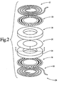
- FIG. 2 depicts the various components of the lower magnet coil assembly 2b, it being understood that lower magnet coil assembly 2b is also representative of the upper magnet coil assembly 2a.
- the magnet coil assembly 2b includes a pair of cooling members 10, 12, a pair of magnet coils 14, 16, and electrical insulation layers 18, 20, 22.
- Each cooling member 10 is fabricated from tubing wound in a generally planar annular configuration.
- the tubing is preferably copper tubing having an 8 x 12 mm rectangular exterior cross section and is bifilar wound, with the 12 mm dimension of the tube running in the radial direction.
- Other materials and cross sections may also be used, provided that tubing is wound so that a substantially flat portion of the tubing cross section may be placed facing and in thermal contact with the magnet coil 14.
- Placed between each of the adjacent layers of tubing is thermal insulation such as PVC having a thickness of approximately 2 mm.
- Typical conductivity for a polymer such as PVC is approximately 0.3 w/mK.
- the tubing is wound so that adjacent turns of tubing are substantially adjacent, though separated by thermal insulation 28.
- the member has in inlet 24 through which a coolant such as water is introduced, and an outlet 26 from which the coolant exits after having flowed through the tubing.
- Mechanical spacers 29a, 29b are placed in the inner layers of the winding to account for spaces caused by the bend of the bifilar wound tubing and thus maintain the circularity of the cooling member 10.
- An electrical insulation layer 18 is located between the cooling member 10 and the driver coil 14.
- the insulation layer 18 should provide a desired degree of electrical isolation consistent with good thermal communication between the cooling spiral 10 and the driver coil 14.
- the insulation layer 18 is of an annular shape and contains a plurality of perforations or holes 28.
- a uniform layer of epoxy adhesive is used to fasten the cooling member 10 to the driver coil 14.
- the epoxy preferably provides a high degree of thermal conductivity, which in practice means a high filler content, and a desired degree of electrical isolation. Because the insulation layer 18 contains numerous perforations 28, the epoxy layer joins the cooling member 10 and the driver coil 14 over a substantial portion of their surface.
- the epoxy preferably has a minimum of voids so as to maximize thermal communication between the cooling member 10 and the driver coil 14.
- the cooling member 10 may also be coated with a layer of lacquer.
- a generally planar driver coil 14 contains a plurality of turns of a spiral-wound electrical conductor 30 such as aluminium. An electrical connection is made at one end of the conductor 30 at the inside of the spiral and at the other end at the outside of the spiral.
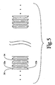
- a cross section of a portion of the driver coil 14 showing a representative portion of the coil windings is shown in Figure 5. While gaps are shown between the windings for ease of illustration, it will be appreciated that in practice the winding are substantially adjacent.
- the conductor 30 is characterized by a generally rectangular cross section having beveled edges 32a and 32b.
- An electrical insulation layer 34 such as Mylar is placed between the turns of the conductor 30, thus preventing the turns from making electrical contact.
- the beveled surfaces prevent electrical contact near the upper and lower edges of the conductor 30 in the event that the vertical dimensions of the insulating layer 34 or conductor 30 should vary or if the insulating layer 34 is not precisely positioned.
- the nominal dimensions of the bevels 32a, 32b and the height of the insulating layer 34 are chosen so that electrical insulation between the conductor 30 turns is achieved despite variations in the material and assembly techniques while preventing or minimizing protrusion of the insulating layer 34 beyond the vertical extent or edges of the conductor 30.
- An electrical insulation layer 20 is placed between the driver coils 14, 16.
- the insulation layer 18 is selected to provide a desired degree of electrical isolation between the driver coils 14, 16.
- the coils 14, 16 are bonded to the insulation layer using an epoxy.
- other arrangements, such as those described above in regard to insulation layer 18, may be used if improved thermal communication between driver coils 14, 16 is desired.
- a current source provides an electrical current to the magnet assemblies 2a, 2b so that a desired magnetic field Bo is generated, and coolant such as water is caused to flow through passages defined by the material of the cooling members 10, 12.
- coolant such as water
- the cooling members may be placed in good thermal contact with the driver coils 12, 14 during the manufacturing process, for example by applying pressure during assembly.
- the system is relatively tolerant of variations in the surfaces of the cooling member and driver coils. Because protrusions of the relatively thermally insulating Mylar beyond the surface of the driver coils are minimized, thermal communication between the cooling members and the driver coils 12, 14 is further enhanced.
- each cooling member includes a first inlet manifold and first exit manifold which are associated with a first plurality of cooling passages, and a second inlet manifold and second exit manifold which are associated with a second plurality of passages.
- the first and second passages are interleaved, with the direction of coolant flow in opposite directions.
- coolant entering the inlet side 24 of the cooling member is cooler than that exiting through the outlet 26.
- a particular advantage of the bifilar winding of the cooling member is that variation in temperature of the cooling member in the radial direction are minimized. This in turn minimizes variation in temperature of the driver coils 12, 14 in the radial direction. Effective thermal insulation between the individual turns in the cooling member also improves the thermal efficiency of the cooling member.
- the invention has been described in relation to a C-shaped magnet apparatus. It will be appreciated that the invention can be used with other magnet configurations, such as the so-called four-poster type, the so-called H-form, or other configurations which provide a return path for the magnet flux.
- a first advantage of the described embodiment is that improved thermal performance in a magnet system is provided while minimizing cost and complexity, including that of the cooling system. Another advantage is that improved thermal communication between the cooling member and the driver coil is provided. Not only can absolute temperature of the magnet coils be reduced, but also temperature gradients within the coils themselves can be minimized. Yet another advantage is that a separate cooling flange may be eliminated. Another advantage is that the turns of the magnet coil are insulated using a technique which avoids the disadvantages of the anodized approach but which does not degrade the performance of the cooling system.
Landscapes
- Physics & Mathematics (AREA)
- Electromagnetism (AREA)
- Engineering & Computer Science (AREA)
- Power Engineering (AREA)
- Condensed Matter Physics & Semiconductors (AREA)
- General Physics & Mathematics (AREA)
- Magnetic Resonance Imaging Apparatus (AREA)
- Transformer Cooling (AREA)
Abstract
Description
- The present invention relates to magnet coil assemblies, and more particularly to driver coils and cooling techniques for use in resistive electromagnets. The present invention finds particular application in the field of magnetic resonance imaging (MRI).
- MRI is widely used for imaging anatomical and other structures. A commonly used type of magnet for MRI systems is the superconducting type, which is capable of generating field strengths in the range of 0.5-2 Tesla (T). Superconducting magnets are, however, relatively expensive to manufacture and operate.
- At lower fields, for example in the range of 0.1 to 0.3 T, resistive magnets are commonly used to produce magnetic fields for MRI applications. Resistive magnets typically include one more magnet driver coils operating in cooperation with a suitable magnet structure, the magnetic field strength being generally proportional to the current through the coils. A limitation on magnet performance, however, is the heat generated in the resistance of the driver coils. As a result, cooling systems have been used to remove this excess heat.
- To provide the necessary cooling, annular cooling flanges or discs fabricated from a material such as aluminium have been placed in thermal contact with the magnet coils. Channels having a size and depth sufficient to accommodate and retain copper tubing having a round cross section have been included on one side of the cooling flange, which has had a thickness greater than that of the tubing. The channels and tubing are arranged in a bifilar wound pattern so that the inlet and outlet of the tubing are both accessible from the outer radius of the cooling flange. The cooling flanges have then been placed against the driver coils, with the tubing preferably on the side of the flange facing away from the magnet coil. In operation, a coolant such as water has been caused to flow through the tubing.
- In practice, however, neither the surface of the driver coil nor surface of the cooling flange are perfectly flat. The resultant gaps degrade the thermal conductivity between the coil and flange. There have also been radial gaps between the channels and hence the turns of tubing, also reducing thermal efficiency.
- In magnet systems having two driver coils on each pole of the magnet it has been necessary to use three cooling flanges. The structure associated with each pole has thus included a first cooling flange, a driver coil having its first side electrically insulated from but in thermal contact with the first cooling flange, a second cooling flange located between the second side of the first driver coil and first side of a second driver coil (the second cooling flange being in thermal contact with but electrically insulated from the driver coils), the second driver coil, and a third cooling flange electrically insulated from but in thermal contact with the second side of the second driver coil.
- Driver coils have also included many turns of a conductor such as aluminium arranged in a generally planar, disc-shaped coil. The conductor has had a rectangular cross-section, with the conductor wound or coiled from an inner to an outer radius in the form of an annulus or disc. To insulate between the multiple conductor turns, an anodized aluminium conductor has been used. A disadvantage of anodized aluminium, however, is its cost. A further disadvantage is that defects in the anodization may result in short circuits between coil turns, with a corresponding deleterious effect on magnet performance.
- In accordance with a first aspect of the invention, a magnet coil assembly includes a generally planar driver coil. Current flowing through the driver coil causes heat to be generated. The assembly also includes tubing which contains the flow a of coolant. The tubing has a substantially planar exterior portion which faces and is in thermal communication with the surface of the driver coil.
- According to a more limited aspect of the invention, the tubing has a rectangular exterior cross section.
- According to another more limited aspect of the invention, the tubing is wound to define a plurality of generally planar turns. A layer of thermally insulating material having a thickness less than that of the tubing may be located between the turns.
- According to yet another more limited aspect of the invention, the tubing is bifilar wound.
- According to another more limited aspect, the driver coil and the and the tubing are separated by a layer of electrical insulation which defines a plurality of holes. According to a still more limited aspect, an epoxy is located between the insulation and the driver coil.
- According to another aspect of the invention, a magnet for use in MRI includes two pole pieces in an opposed relationship which define an imaging region. A driver coil and a material for defining a cooling passage are associated with the first pole piece. The material has a substantially planar portion facing and in thermal communication with the driver coil. A driver coil and material for defining a cooling passage are also associated with the second pole piece. The material has a substantially planar portion facing and in thermal communication with the driver coil associated with the second pole piece.
- According to a more limited aspect of the invention, the driver coil associated with the first pole piece includes a conductor which has a generally rectangular cross section. An edge of the conductor which is adjacent to the material is beveled. According to a still more limited aspect, the conductor is wound to define a plurality of generally planar turns. The turns are separated by a layer of electrical insulation. According to a still more limited aspect, the electrical insulation does not extend past the edge of the conductor facing the material in thermal communication therewith.
- According to another aspect of the invention, a magnet coil assembly for use in magnetic resonance imaging includes a first driver coil and material which defines a cooling passage. The material has a substantially planar portion which faces and is in thermal communication with the first surface of the first driver coil. A second surface of the second driver coil is adjacent the second surface of the first driver coil. Material which defines a cooling passage and has a substantially planar portion faces and is in thermal communication with the first surface of the first driver coil.
- One way of carrying out the invention will now be described in greater detail, by way of example, with reference to the accompanying drawings, in which:
- Figure 1 depicts an MRI apparatus according to the present invention;
- Figure 2 is an exploded view of a magnet coil assembly;
- Figure 3 is a top view of a cooling member;
- Figure 4 is a top view of a perforated insulating layer; and
- Figure 5 is a sectional view of a portion of the windings of a driver coil along line 5-5 of Figure 2.
-
- With reference to Figure 1, an MRI apparatus which produces images of the anatomy of patient 1 includes a generally C-shaped magnet body 3. The patient 1 is placed in an imaging region located between the
pole pieces 23. Current flowing in the driver coils contained incoil assemblies Necks 4 connect thepole pieces 23 to the body 3 of the magnet, thereby providing a return path for the body of the magnet. -
Gradient coils 6 generate time-varying gradient magnetic fields, preferably in three orthogonal directions (e.g., x, y, z). As known in the art, the MRI apparatus 100 also includes RF transmit and receive coils (not shown) for exciting magnetic resonance of materials within the imaging region and detecting signals excited thereby. As is also conventional in the art, associated signal processing and computer apparatus generates and displays images of the internal anatomy of the patient on a CRT or other suitable monitor. - Figure 2 depicts the various components of the lower
magnet coil assembly 2b, it being understood that lowermagnet coil assembly 2b is also representative of the uppermagnet coil assembly 2a. - With reference to Figure 1, 2, and 3, the
magnet coil assembly 2b includes a pair ofcooling members magnet coils electrical insulation layers cooling member 10 is fabricated from tubing wound in a generally planar annular configuration. The tubing is preferably copper tubing having an 8 x 12 mm rectangular exterior cross section and is bifilar wound, with the 12 mm dimension of the tube running in the radial direction. Other materials and cross sections may also be used, provided that tubing is wound so that a substantially flat portion of the tubing cross section may be placed facing and in thermal contact with themagnet coil 14. Placed between each of the adjacent layers of tubing is thermal insulation such as PVC having a thickness of approximately 2 mm. Typical conductivity for a polymer such as PVC is approximately 0.3 w/mK. The tubing is wound so that adjacent turns of tubing are substantially adjacent, though separated bythermal insulation 28. The member has ininlet 24 through which a coolant such as water is introduced, and anoutlet 26 from which the coolant exits after having flowed through the tubing.Mechanical spacers member 10. - An
electrical insulation layer 18 is located between the coolingmember 10 and thedriver coil 14. Theinsulation layer 18 should provide a desired degree of electrical isolation consistent with good thermal communication between the coolingspiral 10 and thedriver coil 14. With reference to Figure 4, theinsulation layer 18 is of an annular shape and contains a plurality of perforations or holes 28. A uniform layer of epoxy adhesive is used to fasten the coolingmember 10 to thedriver coil 14. The epoxy preferably provides a high degree of thermal conductivity, which in practice means a high filler content, and a desired degree of electrical isolation. Because theinsulation layer 18 containsnumerous perforations 28, the epoxy layer joins the coolingmember 10 and thedriver coil 14 over a substantial portion of their surface. The epoxy preferably has a minimum of voids so as to maximize thermal communication between the coolingmember 10 and thedriver coil 14. To improve electrical isolation, the coolingmember 10 may also be coated with a layer of lacquer. - With reference to Figures 2 and 5, a generally
planar driver coil 14 contains a plurality of turns of a spiral-woundelectrical conductor 30 such as aluminium. An electrical connection is made at one end of theconductor 30 at the inside of the spiral and at the other end at the outside of the spiral. A cross section of a portion of thedriver coil 14 showing a representative portion of the coil windings is shown in Figure 5. While gaps are shown between the windings for ease of illustration, it will be appreciated that in practice the winding are substantially adjacent. - The
conductor 30 is characterized by a generally rectangular cross section having bevelededges electrical insulation layer 34 such as Mylar is placed between the turns of theconductor 30, thus preventing the turns from making electrical contact. The beveled surfaces prevent electrical contact near the upper and lower edges of theconductor 30 in the event that the vertical dimensions of the insulatinglayer 34 orconductor 30 should vary or if the insulatinglayer 34 is not precisely positioned. In practice, the nominal dimensions of thebevels layer 34 are chosen so that electrical insulation between theconductor 30 turns is achieved despite variations in the material and assembly techniques while preventing or minimizing protrusion of the insulatinglayer 34 beyond the vertical extent or edges of theconductor 30. This in turn facilitates thermal communication between the conductor and adjacent layers or structures such as the coolingmember 10. In an arrangement where the conductor has a nominal height of 100 mm and a nominal thickness of 0.5 mm, satisfactory results have been achieved withbevels insulation layer 34 having a height of 100 mm. - An
electrical insulation layer 20 is placed between the driver coils 14, 16. Theinsulation layer 18 is selected to provide a desired degree of electrical isolation between the driver coils 14, 16. Thecoils insulation layer 18, may be used if improved thermal communication between driver coils 14, 16 is desired. - While the foregoing description has been directed primarily to cooling
member 10, insulatinglayer 18, anddriver coil 14, it will be appreciated that it applies equally todriver coil 16, insulatinglayer 22, and coolingmember 22. After assembly, the entire structure is hermetically sealed using epoxy, a glass fibre laminate, or like technique. - In operation, a current source provides an electrical current to the
magnet assemblies members - Although the cooling member has been described in terms of bifilar wound tubing, other configurations are possible. Thus, for example, coolant may be introduced to the cooling members through headers or manifolds, each feeding a plurality of cooling passages. In one embodiment, each cooling member includes a first inlet manifold and first exit manifold which are associated with a first plurality of cooling passages, and a second inlet manifold and second exit manifold which are associated with a second plurality of passages. The first and second passages are interleaved, with the direction of coolant flow in opposite directions.
- As will be appreciated, coolant entering the
inlet side 24 of the cooling member is cooler than that exiting through theoutlet 26. A particular advantage of the bifilar winding of the cooling member is that variation in temperature of the cooling member in the radial direction are minimized. This in turn minimizes variation in temperature of the driver coils 12, 14 in the radial direction. Effective thermal insulation between the individual turns in the cooling member also improves the thermal efficiency of the cooling member. - The invention has been described in relation to a C-shaped magnet apparatus. It will be appreciated that the invention can be used with other magnet configurations, such as the so-called four-poster type, the so-called H-form, or other configurations which provide a return path for the magnet flux.
- A first advantage of the described embodiment is that improved thermal performance in a magnet system is provided while minimizing cost and complexity, including that of the cooling system. Another advantage is that improved thermal communication between the cooling member and the driver coil is provided. Not only can absolute temperature of the magnet coils be reduced, but also temperature gradients within the coils themselves can be minimized. Yet another advantage is that a separate cooling flange may be eliminated. Another advantage is that the turns of the magnet coil are insulated using a technique which avoids the disadvantages of the anodized approach but which does not degrade the performance of the cooling system.
- The invention has been described with reference to the preferred embodiment. Obviously, modifications and alterations will occur to others upon reading an understanding the preceding description. It is intended that the invention be construed as including all such modifications an alterations insofar as they come within the scope of the appended claims or the equivalents thereof.
Claims (15)
- A magnet coil assembly comprising: a first generally planar driver coil (14, 16) having at least a first surface, heat being generated in the first driver coil in response to the flow of electrical current; and a first material (10, 12) defining a passage capable of containing the flow of a coolant therethrough which removes heat generated in the first driver coil, the first material having a substantially planar portion facing and in thermal communication with the first driver coil.
- A coil assembly as claimed in claim 1, wherein the first material comprises tubing.
- A coil assembly as claimed in claim 2, wherein the tubing has a rectangular exterior cross section.
- A coil assembly as claimed in claim 2 or claim 3, wherein the tubing is wound to define a plurality of generally planar turns.
- A coil assembly as claimed in claim 4, including a layer of thermally insulating material (28) between the turns.
- A coil assembly as claimed in claim 5, wherein the thermally insulating material (28) has a thickness less than that of the tubing.
- A coil assembly as claimed in any one of claims 2 to 6, wherein the tubing is bifilar wound.
- A coil assembly as claimed in any one of claims 1 to 7, wherein the first driver coil (14, 16) and the first material (10, 12) are separated by a layer of electrical insulation (18, 22), the layer of electrical insulation having a plurality of holes.
- A coil assembly as claimed in claim 8, comprising adhesive between the layer of electrical insulation (18, 22) and the first driver coil (14, 16).
- A coil assembly as claimed in claim 9, wherein the adhesive is an epoxy having a high thermal conductivity.
- A coil assembly as claimed in any one of claims 1 to 10, wherein the coolant comprises water.
- A coil assembly as claimed in any one of claims 1 to 11, wherein the first driver coil (14, 16) comprises a conductor (30) having a generally rectangular cross section, an edge of the conductor adjacent the first material having a bevel (32a, 32b).
- A coil assembly as claimed in claim 12, wherein the conductor (30) is wound so as to define a plurality of generally planar turns and the turns are separated by a layer of electrical insulation (34).
- A coil assembly as claimed in any one of claims 1 to 13, wherein the first material (10, 12) facing and in thermal communication with the first surface of the first driver coil defines a plurality of passages (24, 26).
- A coil assembly as claimed in any one of claims 1 to 14, further including a second generally planar driver coil (14, 16) having at least a first surface, heat being generated in the second driver coil in response to the flow of electrical current; and a second material (10, 12) defining a passage capable of containing the flow of a coolant therethrough which removes heat generated in the magnet coil, the second material having a substantially planar portion facing and in thermal communication with the second driver coil, wherein the first driver coil is associated with a first pole piece (23) and the second driver coil is associated with a second pole piece (23), the first and second pole pieces in an opposed relationship and defining an image region therebetween for use in magnetic resonance imaging.
Applications Claiming Priority (2)
| Application Number | Priority Date | Filing Date | Title |
|---|---|---|---|
| US08/985,935 US5936502A (en) | 1997-12-05 | 1997-12-05 | Magnet coils for MRI |
| US985935 | 1997-12-05 |
Publications (3)
| Publication Number | Publication Date |
|---|---|
| EP0921537A2 true EP0921537A2 (en) | 1999-06-09 |
| EP0921537A3 EP0921537A3 (en) | 2000-04-12 |
| EP0921537B1 EP0921537B1 (en) | 2003-04-23 |
Family
ID=25531923
Family Applications (1)
| Application Number | Title | Priority Date | Filing Date |
|---|---|---|---|
| EP98309985A Expired - Lifetime EP0921537B1 (en) | 1997-12-05 | 1998-12-04 | Magnet coil assembly |
Country Status (3)
| Country | Link |
|---|---|
| US (1) | US5936502A (en) |
| EP (1) | EP0921537B1 (en) |
| DE (1) | DE69813734D1 (en) |
Cited By (11)
| Publication number | Priority date | Publication date | Assignee | Title |
|---|---|---|---|---|
| WO2008078257A2 (en) | 2006-12-20 | 2008-07-03 | Philips Intellectual Property & Standards Gmbh | Arrangement for influencing and/or detecting magnetic particles in a region of action and method of producing a disk shaped coil |
| WO2011039417A1 (en) * | 2009-09-30 | 2011-04-07 | Trafotek Oy | Method for cooling a coil, coil cooling system and liquid cooled coil |
| EP2382490A2 (en) * | 2009-01-13 | 2011-11-02 | Aspect Magnet Technologies Ltd. | Means and methods for providing high resolution mri |
| CN107110932A (en) * | 2014-09-05 | 2017-08-29 | 海珀菲纳研究股份有限公司 | low-field magnetic resonance imaging method and apparatus |
| US10750973B2 (en) | 2010-07-07 | 2020-08-25 | Aspect Imaging Ltd. | Devices and methods for a neonate incubator, capsule and cart |
| US10847294B2 (en) | 2017-07-10 | 2020-11-24 | Aspect Imaging Ltd. | System for generating a magnetic field |
| US10847295B2 (en) | 2016-08-08 | 2020-11-24 | Aspect Imaging Ltd. | Device, system and method for obtaining a magnetic measurement with permanent magnets |
| US10996297B2 (en) | 2009-06-30 | 2021-05-04 | Aspect Imaging Ltd. | Method of assembling a magnetic resonance device |
| US11287497B2 (en) | 2016-08-08 | 2022-03-29 | Aspect Imaging Ltd. | Device, system and method for obtaining a magnetic measurement with permanent magnets |
| US11366188B2 (en) | 2016-11-22 | 2022-06-21 | Hyperfine Operations, Inc. | Portable magnetic resonance imaging methods and apparatus |
| US11841408B2 (en) | 2016-11-22 | 2023-12-12 | Hyperfine Operations, Inc. | Electromagnetic shielding for magnetic resonance imaging methods and apparatus |
Families Citing this family (13)
| Publication number | Priority date | Publication date | Assignee | Title |
|---|---|---|---|---|
| GB2341447B (en) * | 1998-09-11 | 2003-08-20 | Oxford Magnet Tech | Temperature control system for a permanent magnetic mri system |
| JP3283242B2 (en) * | 1999-06-21 | 2002-05-20 | ジーイー横河メディカルシステム株式会社 | Gradient coil manufacturing method, gradient coil and MRI apparatus |
| US7211919B2 (en) * | 1999-08-16 | 2007-05-01 | American Superconductor Corporation | Thermally-conductive stator support structure |
| US6717408B2 (en) | 2001-04-05 | 2004-04-06 | Intermagnetics General Corporation | Support structure for open MRI apparatus |
| US6972655B2 (en) * | 2003-08-04 | 2005-12-06 | Lockheed Martin Corporation | Construction for cooled solenoid |
| US7557577B2 (en) * | 2003-12-08 | 2009-07-07 | Siemens Aktiengesselschaft | Water-soluble paramagnetic substance reducing the relaxation time of the coolant in an MRI system |
| US7619345B2 (en) * | 2006-01-30 | 2009-11-17 | American Superconductor Corporation | Stator coil assembly |
| DE102006014305B4 (en) * | 2006-03-28 | 2011-03-31 | Siemens Ag | Cooling device for the arrangement between two surface coils of a gradient coil, gradient coil comprising such a cooling device and method for He setting of such a gradient coil |
| US10526932B2 (en) | 2008-08-01 | 2020-01-07 | David Meisel | Engine electronic valve actuation |
| US8210139B2 (en) * | 2008-08-01 | 2012-07-03 | David Meisel | Engine electronic valve actuation |
| DE102012208545A1 (en) * | 2012-05-22 | 2013-11-28 | Schmidbauer Transformatoren und Gerätebau GmbH | Water-cooled electrical coil for e.g. electrical throttle and electrical transformer, has cooling arrangement comprising cooling conduit with cooling conduit wall for passing cooling fluid, and cooling structure arranged outside on winding |
| KR20190043129A (en) | 2016-06-22 | 2019-04-25 | 뷰레이 테크놀로지스 인크. | Magnetic Resonance Imaging at Weak Field Strength |
| US11209509B2 (en) | 2018-05-16 | 2021-12-28 | Viewray Technologies, Inc. | Resistive electromagnet systems and methods |
Citations (4)
| Publication number | Priority date | Publication date | Assignee | Title |
|---|---|---|---|---|
| FR2302580A1 (en) * | 1975-02-28 | 1976-09-24 | Tioxide Group Ltd | POLYPHASED REACTOR COIL |
| US4721914A (en) * | 1984-05-01 | 1988-01-26 | The United States Of America As Represented By The United States Department Of Energy | Apparatus for unilateral generation of a homogeneous magnetic field |
| JPH01276707A (en) * | 1988-04-28 | 1989-11-07 | Yokogawa Medical Syst Ltd | Coil cooling device, normal conducting magnet provided with same and manufacture thereof |
| WO1990008390A1 (en) * | 1989-01-13 | 1990-07-26 | Sundstrand Corporation | Inductor transformer cooling apparatus |
Family Cites Families (3)
| Publication number | Priority date | Publication date | Assignee | Title |
|---|---|---|---|---|
| US4667174A (en) * | 1985-08-23 | 1987-05-19 | Resonex, Inc. | Magnet assembly for magnetic resonance imaging and method of manufacture |
| US5173678A (en) * | 1990-09-10 | 1992-12-22 | Gte Laboratories Incorporated | Formed-to-shape superconducting coil |
| US5554929A (en) * | 1993-03-12 | 1996-09-10 | Doty Scientific, Inc. | Crescent gradient coils |
-
1997
- 1997-12-05 US US08/985,935 patent/US5936502A/en not_active Expired - Fee Related
-
1998
- 1998-12-04 EP EP98309985A patent/EP0921537B1/en not_active Expired - Lifetime
- 1998-12-04 DE DE69813734T patent/DE69813734D1/en not_active Expired - Lifetime
Patent Citations (4)
| Publication number | Priority date | Publication date | Assignee | Title |
|---|---|---|---|---|
| FR2302580A1 (en) * | 1975-02-28 | 1976-09-24 | Tioxide Group Ltd | POLYPHASED REACTOR COIL |
| US4721914A (en) * | 1984-05-01 | 1988-01-26 | The United States Of America As Represented By The United States Department Of Energy | Apparatus for unilateral generation of a homogeneous magnetic field |
| JPH01276707A (en) * | 1988-04-28 | 1989-11-07 | Yokogawa Medical Syst Ltd | Coil cooling device, normal conducting magnet provided with same and manufacture thereof |
| WO1990008390A1 (en) * | 1989-01-13 | 1990-07-26 | Sundstrand Corporation | Inductor transformer cooling apparatus |
Non-Patent Citations (1)
| Title |
|---|
| PATENT ABSTRACTS OF JAPAN vol. 014, no. 045 (E-0880), 26 January 1990 (1990-01-26) -& JP 01 276707 A (YOKOGAWA MEDICAL SYST LTD), 7 November 1989 (1989-11-07) * |
Cited By (19)
| Publication number | Priority date | Publication date | Assignee | Title |
|---|---|---|---|---|
| WO2008078257A3 (en) * | 2006-12-20 | 2008-11-27 | Philips Intellectual Property | Arrangement for influencing and/or detecting magnetic particles in a region of action and method of producing a disk shaped coil |
| WO2008078257A2 (en) | 2006-12-20 | 2008-07-03 | Philips Intellectual Property & Standards Gmbh | Arrangement for influencing and/or detecting magnetic particles in a region of action and method of producing a disk shaped coil |
| EP2382490A4 (en) * | 2009-01-13 | 2013-01-09 | Aspect Magnet Technologies Ltd | Means and methods for providing high resolution mri |
| EP2382490A2 (en) * | 2009-01-13 | 2011-11-02 | Aspect Magnet Technologies Ltd. | Means and methods for providing high resolution mri |
| US10996297B2 (en) | 2009-06-30 | 2021-05-04 | Aspect Imaging Ltd. | Method of assembling a magnetic resonance device |
| WO2011039417A1 (en) * | 2009-09-30 | 2011-04-07 | Trafotek Oy | Method for cooling a coil, coil cooling system and liquid cooled coil |
| US10750973B2 (en) | 2010-07-07 | 2020-08-25 | Aspect Imaging Ltd. | Devices and methods for a neonate incubator, capsule and cart |
| US11175364B2 (en) | 2014-09-05 | 2021-11-16 | Hyperfine, Inc. | Low field magnetic resonance imaging methods and apparatus |
| EP3189342A4 (en) * | 2014-09-05 | 2018-06-20 | Hyperfine Research Inc. | Low field magnetic resonance imaging methods and apparatus |
| US10495712B2 (en) | 2014-09-05 | 2019-12-03 | Hyperfine Research, Inc. | Low field magnetic resonance imaging methods and apparatus |
| CN107110932B (en) * | 2014-09-05 | 2020-09-01 | 海珀菲纳研究股份有限公司 | Low field magnetic resonance imaging method and apparatus |
| US11397233B2 (en) | 2014-09-05 | 2022-07-26 | Hyperfine Operations, Inc. | Ferromagnetic augmentation for magnetic resonance imaging |
| CN107110932A (en) * | 2014-09-05 | 2017-08-29 | 海珀菲纳研究股份有限公司 | low-field magnetic resonance imaging method and apparatus |
| US10847295B2 (en) | 2016-08-08 | 2020-11-24 | Aspect Imaging Ltd. | Device, system and method for obtaining a magnetic measurement with permanent magnets |
| US11287497B2 (en) | 2016-08-08 | 2022-03-29 | Aspect Imaging Ltd. | Device, system and method for obtaining a magnetic measurement with permanent magnets |
| US11366188B2 (en) | 2016-11-22 | 2022-06-21 | Hyperfine Operations, Inc. | Portable magnetic resonance imaging methods and apparatus |
| US11841408B2 (en) | 2016-11-22 | 2023-12-12 | Hyperfine Operations, Inc. | Electromagnetic shielding for magnetic resonance imaging methods and apparatus |
| US10847294B2 (en) | 2017-07-10 | 2020-11-24 | Aspect Imaging Ltd. | System for generating a magnetic field |
| US11887778B2 (en) | 2017-07-10 | 2024-01-30 | Aspect Imaging Ltd. | System for generating a magnetic field |
Also Published As
| Publication number | Publication date |
|---|---|
| EP0921537A3 (en) | 2000-04-12 |
| US5936502A (en) | 1999-08-10 |
| DE69813734D1 (en) | 2003-05-28 |
| EP0921537B1 (en) | 2003-04-23 |
Similar Documents
| Publication | Publication Date | Title |
|---|---|---|
| EP0921537B1 (en) | Magnet coil assembly | |
| US7439741B2 (en) | Thermal management apparatus and uses thereof | |
| CN1090010C (en) | Arrangement to minimize eddy currents in MR imagers | |
| US6236207B1 (en) | Coil system for magnetic resonance systems with integrated cooling unit | |
| US7489131B2 (en) | System and apparatus for direct cooling of gradient coils | |
| EP1650577B1 (en) | Magnetic Resonance Imaging Device Comprising Gradient Bore Cooling and RF Shield | |
| US7135863B2 (en) | Thermal management system and method for MRI gradient coil | |
| JP4039495B2 (en) | Magnetic field generator for MRI | |
| JPH0447964B2 (en) | ||
| JP7232197B2 (en) | Cooling of gradient coils in magnetic resonance imaging systems | |
| JP7177779B2 (en) | Cooling of Gradient Coils in Magnetic Resonance Imaging Systems | |
| JP4330477B2 (en) | Gradient magnetic field coil and magnetic resonance imaging apparatus using the same | |
| JP2016049159A (en) | Superconducting magnet and magnetic resonance imaging apparatus | |
| JP2666773B2 (en) | Gradient magnetic field generator | |
| WO2018150819A1 (en) | Superconducting magnet device and magnetic resonance imaging apparatus in which same is used | |
| RU2074431C1 (en) | Resistive electromagnet for nmr-tomograph | |
| JP3529442B2 (en) | Superconducting coil | |
| JP2004073288A (en) | Coil device | |
| JP2001149337A (en) | Magnetic resonance imaging device | |
| JPH0648646B2 (en) | Superconducting magnet device | |
| JP3482564B2 (en) | Normal conduction high magnetic field coil device | |
| GB2470137A (en) | Cooling of gradient coils | |
| EP1464979A1 (en) | Coil structure for magnetic resonance imaging | |
| JPS609107A (en) | Electromagnetic coil |
Legal Events
| Date | Code | Title | Description |
|---|---|---|---|
| PUAI | Public reference made under article 153(3) epc to a published international application that has entered the european phase |
Free format text: ORIGINAL CODE: 0009012 |
|
| AK | Designated contracting states |
Kind code of ref document: A2 Designated state(s): DE FR NL |
|
| AX | Request for extension of the european patent |
Free format text: AL;LT;LV;MK;RO;SI |
|
| PUAL | Search report despatched |
Free format text: ORIGINAL CODE: 0009013 |
|
| AK | Designated contracting states |
Kind code of ref document: A3 Designated state(s): AT BE CH CY DE DK ES FI FR GB GR IE IT LI LU MC NL PT SE |
|
| AX | Request for extension of the european patent |
Free format text: AL;LT;LV;MK;RO;SI |
|
| RIC1 | Information provided on ipc code assigned before grant |
Free format text: 7H 01F 7/20 A, 7G 01R 33/38 B |
|
| 17P | Request for examination filed |
Effective date: 20001004 |
|
| AKX | Designation fees paid |
Free format text: DE FR NL |
|
| 17Q | First examination report despatched |
Effective date: 20010323 |
|
| RAP1 | Party data changed (applicant data changed or rights of an application transferred) |
Owner name: MARCONI MEDICAL SYSTEMS FINLAND, INC. |
|
| GRAH | Despatch of communication of intention to grant a patent |
Free format text: ORIGINAL CODE: EPIDOS IGRA |
|
| GRAH | Despatch of communication of intention to grant a patent |
Free format text: ORIGINAL CODE: EPIDOS IGRA |
|
| GRAA | (expected) grant |
Free format text: ORIGINAL CODE: 0009210 |
|
| AK | Designated contracting states |
Designated state(s): DE FR NL |
|
| PG25 | Lapsed in a contracting state [announced via postgrant information from national office to epo] |
Ref country code: NL Free format text: LAPSE BECAUSE OF FAILURE TO SUBMIT A TRANSLATION OF THE DESCRIPTION OR TO PAY THE FEE WITHIN THE PRESCRIBED TIME-LIMIT Effective date: 20030423 Ref country code: FR Free format text: LAPSE BECAUSE OF FAILURE TO SUBMIT A TRANSLATION OF THE DESCRIPTION OR TO PAY THE FEE WITHIN THE PRESCRIBED TIME-LIMIT Effective date: 20030423 |
|
| REF | Corresponds to: |
Ref document number: 69813734 Country of ref document: DE Date of ref document: 20030528 Kind code of ref document: P |
|
| PG25 | Lapsed in a contracting state [announced via postgrant information from national office to epo] |
Ref country code: DE Free format text: LAPSE BECAUSE OF FAILURE TO SUBMIT A TRANSLATION OF THE DESCRIPTION OR TO PAY THE FEE WITHIN THE PRESCRIBED TIME-LIMIT Effective date: 20030724 |
|
| NLV1 | Nl: lapsed or annulled due to failure to fulfill the requirements of art. 29p and 29m of the patents act | ||
| PLBE | No opposition filed within time limit |
Free format text: ORIGINAL CODE: 0009261 |
|
| STAA | Information on the status of an ep patent application or granted ep patent |
Free format text: STATUS: NO OPPOSITION FILED WITHIN TIME LIMIT |
|
| 26N | No opposition filed |
Effective date: 20040126 |
|
| EN | Fr: translation not filed |