EP0921306A2 - Control device for an automotive vehicle starter - Google Patents
Control device for an automotive vehicle starter Download PDFInfo
- Publication number
- EP0921306A2 EP0921306A2 EP98403005A EP98403005A EP0921306A2 EP 0921306 A2 EP0921306 A2 EP 0921306A2 EP 98403005 A EP98403005 A EP 98403005A EP 98403005 A EP98403005 A EP 98403005A EP 0921306 A2 EP0921306 A2 EP 0921306A2
- Authority
- EP
- European Patent Office
- Prior art keywords
- voltage
- management unit
- input
- control
- switch
- Prior art date
- Legal status (The legal status is an assumption and is not a legal conclusion. Google has not performed a legal analysis and makes no representation as to the accuracy of the status listed.)
- Granted
Links
Images

Classifications
-
- F—MECHANICAL ENGINEERING; LIGHTING; HEATING; WEAPONS; BLASTING
- F02—COMBUSTION ENGINES; HOT-GAS OR COMBUSTION-PRODUCT ENGINE PLANTS
- F02N—STARTING OF COMBUSTION ENGINES; STARTING AIDS FOR SUCH ENGINES, NOT OTHERWISE PROVIDED FOR
- F02N11/00—Starting of engines by means of electric motors
- F02N11/08—Circuits or control means specially adapted for starting of engines
- F02N11/087—Details of the switching means in starting circuits, e.g. relays or electronic switches
-
- F—MECHANICAL ENGINEERING; LIGHTING; HEATING; WEAPONS; BLASTING
- F02—COMBUSTION ENGINES; HOT-GAS OR COMBUSTION-PRODUCT ENGINE PLANTS
- F02N—STARTING OF COMBUSTION ENGINES; STARTING AIDS FOR SUCH ENGINES, NOT OTHERWISE PROVIDED FOR
- F02N11/00—Starting of engines by means of electric motors
- F02N11/10—Safety devices
Definitions
- the present invention relates to devices for controlling a motor vehicle starter.
- the invention relates to starter control devices, which have management resources which are permanently under tension.
- This electric motor M is mounted between ground and a + BAT terminal at the supply voltage of the drums.
- the power contactor 1 is constituted by a relay which includes a contact K, which is interposed between the power supply terminal + BAT and the motor M, as well as a winding B with one or more windings.
- This coil B is mounted, between the + BAT terminal and the earth, in series with a controlled switch T1.
- This switch T1 is for example a transistor of the type MOSFET, the grid of which is voltage-controlled by a management unit 2 by its terminal S.
- the management unit 2 is supplied by a link independent of that on which is the start switch 3. It for this purpose has a supply input ⁇ Va ⁇ which is directly connected to the + Bat terminal.
- said management unit 2 is constantly under tension and that's why it incorporates usually a standby system, not shown, which limits consumption electronic when the vehicle is not operating and this prevents too rapid discharge of the battery.
- the operation is as follows.
- the start switch 3 is closed, for example by activation of the ignition key, the standby system is inhibited and management unit 2 takes over all of its functionality. If the different functions of starter protection do not detect any anomaly, the management unit 2 unlocks the transistor "T1", so as to supply the winding B of the contactor 1. Motor M is then supplied.
- management unit 2 detects engine start thermal, transistor T1 is blocked and the starter returns to rest. After a specified time, the system returns to the standby state.
- An object of the invention is to overcome these disadvantages.
- the invention provides a device for the control of a motor vehicle starter with a management unit which is permanently energized and an input of which is connected to a start command, said management unit commanding the starter electric motor supply in function in particular of the signal it receives on said entrance, characterized in that it further comprises additional means which prevent the ordering of the supply of the electric motor by said unit of management if the signal received by said unit on its input connected to the controller does not match so effective at a start command signal.
- the invention also relates to a starter for motor vehicle comprising a control device of the aforementioned type.
- these means 4 make it possible to do not impose a high voltage on the gate of transistor T1 closing only if both the control voltage generated by the management unit 2 on its output ⁇ s ⁇ and the voltage on its input ⁇ e ⁇ are at a high level. This makes it possible to verify that the startup is indeed voluntary.
- these means 4 include a logic gate "N" of the NAND type (NAND according to Anglo-Saxon terminology commonly employed) which receives respectively the input voltages on the input ⁇ e ⁇ and the output ⁇ s ⁇ of the unit 2.
- the output of this door N controls the base of a bipolar transistor T2 of the npn type, the collector is connected to the gate of transistor T1 and of which the transmitter is connected to ground.
- the means 4 do not allow polarization positive of the gate of transistor T1 only if the start switch is closed.
- a resistor R is also mounted between the output ⁇ s ⁇ and the gate of transistor T1, so that gate N actually receives the input voltage generated on output "s", even if T2 is on.
- the means 4 do not include a carries NAND, but an inverter type I mounting, which is mounted between the input ⁇ e ⁇ of unit 2 and the base of the transistor T2.
- This inverter mounting I maintains the grid of T1 at level 0 as long as the start switch 3 is open, regardless of the voltage level of the exits".
- management unit 2 is not controlled by the start switch, but by control signals that another unit of management which manages for example anti-theft security and engine control.
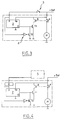
- FIG. 4 A variant in this sense has been illustrated on the FIG. 4, in which a motor M of starter, as well as a control device which behaves, in the same way as those of the figures previous, a contactor 1 which includes a contact power K and a winding B, a switch T1 which controls the supply of winding B and a management 2 which controls the switch T1.
- Said management unit 2 is itself controlled by a second management unit 5, which transmits to it the start order in the form of a coded signal.
- the control device also includes means 4 which do not allow the positive polarization of the gate of transistor T1 only if the start order is actually sent by unit 5, i.e. if the voltage on the input ⁇ e ⁇ is at its high level.
- these means are of the type described with reference to the figure 3. They include an inverter mounting I receiving on its input the voltage injected on the input ⁇ e ⁇ by the decoder 6. The output voltage of this circuit inverter I controls the base of a bipolar transistor T2 npn type, whose transmitter is connected to ground and whose the collector is connected to the gate of transistor T1.
- the status of the decoder output is linked to a inverter "I" as described in variant 1.
Abstract
Description
La présente invention est relative aux dispositifs pour la commande d'un démarreur de véhicule automobile.The present invention relates to devices for controlling a motor vehicle starter.
Plus particulièrement, l'invention concerne les dispositifs de commande de démarreur, qui présentent des moyens de gestion qui sont en permanence sous tension.More particularly, the invention relates to starter control devices, which have management resources which are permanently under tension.
Un exemple de dispositif de ce type est illustré sur la figure 1, sur laquelle on a référencé par M le moteur électrique d'un démarreur de véhicule automobile et par 1 le contacteur de puissance qui commande l'alimentation de ce moteur M.An example of such a device is illustrated on Figure 1, on which we have referenced by M the motor motor vehicle starter and by 1 the power contactor which controls the supply of this engine M.
Ce moteur électrique M est monté entre la masse et une borne + BAT à la tension d'alimentation de la batterie.This electric motor M is mounted between ground and a + BAT terminal at the supply voltage of the drums.
Le contacteur de puissance 1 est constitué par un
relais qui comprend un contact K, qui est interposé entre
la borne d'alimentation +BAT et le moteur M, ainsi qu'un
bobinage B à un ou plusieurs enroulements.The
Ce bobinage B est monté, entre la borne +BAT et la
masse, en série avec un interrupteur commandé T1. Cet
interrupteur T1 est par exemple un transistor de type
MOSFET, dont la grille est commandée en tension par une
unité de gestion 2 par sa borne S.This coil B is mounted, between the + BAT terminal and the
earth, in series with a controlled switch T1. This
switch T1 is for example a transistor of the type
MOSFET, the grid of which is voltage-controlled by a
Cette unité de gestion 2 est généralement constituée par un microprocesseur dont une entrée analogique e est reliée à la borne +Bat par l'interrupteur de démarrage 3 du véhicule. Elle assure différentes fonctions :
- analyse de l'état ouvert ou fermé de
l'interrupteur de
démarrage 3 et gestion de la séquence d'alimentation du moteur M en fonction de cette information ; - arrêt automatique du démarreur lorsque le moteur thermique est démarré ;
- protection du démarreur contre d'éventuelles surcharges ou fausses manoeuvre.
- analysis of the open or closed state of the
start switch 3 and management of the supply sequence of the motor M as a function of this information; - automatic starter stop when the engine is started;
- protection of the starter against possible overloads or incorrect operation.
Dans le montage de la figure 1, l'unité de gestion 2
est alimentée par une liaison indépendante de celle sur
laquelle se trouve l'interrupteur de démarrage 3. Elle
présente à cet effet une entrée d'alimentation 〈〈 Va 〉〉 qui
est directement reliée à la borne +Bat.In the assembly of FIG. 1, the
Par conséquent, ladite unité de gestion 2 est
constamment sous tension et c'est pourquoi elle intègre
habituellement un système de mise en veille, non
représenté, qui permet de limiter la consommation
électronique lorsque le véhicule ne fonctionne pas et
évite ainsi une décharge trop rapide de la batterie.Consequently, said
Le fonctionnement est le suivant. Lorsque
l'interrupteur de démarrage 3 est fermé, par exemple par
l'actionnement de la clé de contact, le système de veille
est inhibé et l'unité de gestion 2 reprend l'ensemble de
ses fonctionnalités. Si les différentes fonctions de
protection du démarreur ne décèlent aucune anomalie,
l'unité de gestion 2 débloque le transistor "T1", de
façon à permettre l'alimentation du bobinage B du
contacteur 1. Le moteur M est alors alimenté. Lorsque
l'unité de gestion 2 détecte le démarrage du moteur
thermique, le transistor T1 se bloque et le démarreur
revient au repos. Après un temps déterminé, le système
revient à l'état de veille.The operation is as follows. When
the
Toutefois, les structures de ce type présentent
plusieurs inconvénients. Notamment, il peut arriver que
des signaux parasites ou une défaillance quelconque de
l'électronique de l'unité de gestion 2 déclenchent
intempestivement la fermeture de l'interrupteur T1.However, structures of this type exhibit
several disadvantages. In particular, it may happen that
spurious signals or any failure of
Cet événement, bien que rare, entraíne des risques importants. Notamment, si le véhicule est à l'arrêt et qu'une vitesse est enclenchée, le véhicule, entraíné par le démarreur, se déplacera de lui-même ; ou encore, si le frein à main est serré ou si aucune vitesse n'est enclenchée, le démarreur peut fonctionner jusqu'à destruction et il y a un risque que les échauffements excessifs qui pourraient en résulter causent un début d'incendie sur le véhicule.This event, although rare, involves risks important. In particular, if the vehicle is stationary and that a gear is engaged, the vehicle, driven by the starter, will move by itself; or if the handbrake is applied or no speed is applied engaged, the starter can operate up to destruction and there is a risk that overheating that could result cause a start fire on the vehicle.
Un but de l'invention est de pallier ces inconvénients.An object of the invention is to overcome these disadvantages.
A cet effet, l'invention propose un dispositif pour la commande d'un démarreur de véhicule automobile comportant une unité de gestion qui est en permanence sous tension et dont une entrée est reliée à un organe de commande de démarrage, ladite unité de gestion commandant l'alimentation du moteur électrique du démarreur en fonction notamment du signal qu'elle reçoit sur ladite entrée, caractérisé en ce qu'il comporte en outre des moyens complémentaires qui empêchent la commande de l'alimentation du moteur électrique par ladite unité de gestion si le signal reçu par ladite unité sur son entrée reliée à l'organe de commande ne correspond pas de façon effective à un signal de commande de démarrage.To this end, the invention provides a device for the control of a motor vehicle starter with a management unit which is permanently energized and an input of which is connected to a start command, said management unit commanding the starter electric motor supply in function in particular of the signal it receives on said entrance, characterized in that it further comprises additional means which prevent the ordering of the supply of the electric motor by said unit of management if the signal received by said unit on its input connected to the controller does not match so effective at a start command signal.
Ce dispositif est avantageusement complété par les différentes caractéristiques suivantes prises seules ou selon toutes leurs combinaisons techniquement possibles :
- l'unité de gestion reçoit sur son entrée qui est reliée à l'organe de commande une tension qui selon que le démarrage est commandé ou non par ledit organe est à un niveau haut ou à un niveau bas et les moyens complémentaires comportent des moyens qui n'autorisent la commande de l'alimentation du moteur électrique par ladite unité de gestion que si la tension sur ladite entrée est à son niveau qui correspond à la commande du démarrage par l'organe de commande ;
- l'unité de gestion génère une tension de sortie dont le niveau commande un interrupteur qui lui-même commande l'alimentation du moteur électrique du démarreur, les moyens complémentaires maintenant la tension de commande dudit interrupteur à un niveau empêchant l'alimentation du moteur électrique lorsque la tension sur l'entrée de l'unité de gestion est à un niveau qui correspond à l'absence de commande de démarrage par l'organe de commande.
- les moyens complémentaires comportent des moyens de type à porte(s) logique(s) qui reçoivent en entrée la tension en entrée de l'unité de gestion et la tension de commande en sortie de celle-ci ;
- la tension en entrée de l'unité de gestion est à un niveau haut lors d'une commande de démarrage par l'organe de commande, l'interrupteur qui commande l'alimentation du moteur électrique étant fermé lorsque sa tension de commande est à un niveau haut, les moyens complémentaires comportant une porte logique NON ET qui reçoit en entrée la tension en entrée de l'unité de gestion et la tension de commande en sortie de celle-ci, la tension en sortie de ladite porte commandant la base d'un transistor qui est monté entre la masse et un point qui est également relié à la sortie de l'unité de gestion et dont la tension commande l'interrupteur ;
- des moyens résistifs sont interposés entre ledit point de commande de l'interrupteur et la sortie de l'unité de gestion ;
- la tension en entrée de l'unité de gestion est à un niveau haut lors d'une commande de démarrage par l'organe de commande, l'interrupteur qui commande l'alimentation du moteur électrique étant fermé lorsque sa tension de commande est à un niveau haut, les moyens complémentaires comportant un montage inverseur qui reçoit en entrée la tension en entrée de l'unité de gestion et dont la tension de sortie commande la base d'un transistor qui est monté entre la masse et un point qui est également relié à la sortie de l'unité de gestion et dont la tension commande l'interrupteur ;
- l'organe de commande est un interrupteur de démarrage ;
- l'organe de commande est constitué par une deuxième unité de gestion qui transmet à la première unité de gestion un ordre de démarrage sous la forme d'un signal codé et ledit dispositif comporte des moyens de décodage qui sont interposés entre l'entrée de la première unité de gestion et la deuxième unité de gestion et qui transforment ce signal codé en un signal de tension.
- the management unit receives at its input which is connected to the control member a voltage which, depending on whether the start-up is controlled or not by said member, is at a high level or at a low level and the complementary means include means which authorize the control of the supply of the electric motor by said management unit only if the voltage on said input is at its level which corresponds to the control of starting by the control member;
- the management unit generates an output voltage, the level of which controls a switch which itself controls the supply of the electric motor to the starter, the complementary means maintaining the control voltage of said switch at a level preventing supply of the electric motor when the voltage on the input of the management unit is at a level which corresponds to the absence of a start command by the control member.
- the complementary means comprise means of the logic gate (s) type which receive as input the voltage at the input of the management unit and the control voltage at the output thereof;
- the input voltage of the management unit is at a high level during a start command by the control member, the switch which controls the supply of the electric motor being closed when its control voltage is at a high level, the additional means comprising a NAND logic gate which receives the input voltage at the input of the management unit and the control voltage at the output thereof, the voltage at the output of said gate controlling the base a transistor which is mounted between ground and a point which is also connected to the output of the management unit and whose voltage controls the switch;
- resistive means are interposed between said switch control point and the output of the management unit;
- the input voltage of the management unit is at a high level during a start command by the control member, the switch which controls the supply of the electric motor being closed when its control voltage is at a high level, the complementary means comprising an inverter assembly which receives the input voltage at the input of the management unit and the output voltage of which controls the base of a transistor which is mounted between ground and a point which is also connected at the output of the management unit and whose voltage controls the switch;
- the control member is a start switch;
- the control member is constituted by a second management unit which transmits to the first management unit a start command in the form of a coded signal and said device comprises decoding means which are interposed between the input of the first management unit and the second management unit and which transform this coded signal into a voltage signal.
L'invention concerne également un démarreur de véhicule automobile comportant un dispositif de commande du type précité.The invention also relates to a starter for motor vehicle comprising a control device of the aforementioned type.
D'autres caractéristiques et avantages de l'invention ressortiront encore de la description qui suit qui est purement illustrative et non limitative et qui doit être lue en regard des dessins annexés sur lesquels :
- la figure 1, déjà analysée, est une représentation schématique d'un dispositif de commande de démarreur conforme à un art antérieur connu ;
- les figures 2 à 4 sont des représentations semblables à celle de la figure1 illustrant trois modes de réalisations possibles conformes à l'invention.
- Figure 1, already analyzed, is a schematic representation of a starter control device according to a known prior art;
- Figures 2 to 4 are representations similar to that of Figure 1 illustrating three possible embodiments according to the invention.
Le dispositif de commande illustré sur la figure 2 comporte, de la même façon que celui de la figure 1 :
- un
contacteur 1 qui comprend un contact de puissance K et un bobinage B, - un interrupteur T1 qui commande l'alimentation du bobinage B,
- une unité de
gestion 2 qui commande l'interrupteur T1.
- a
contactor 1 which includes a power contact K and a winding B, - a switch T1 which controls the supply of the winding B,
- a
management unit 2 which controls the switch T1.
Il diffère principalement de celui qui a été décrit
en référence à la figure 1 par le fait qu'il comporte des
moyens 4 qui permettent d'empêcher la commande de la
fermeture de l'interrupteur T1, lorsque l'interrupteur de
démarrage 3 n'est pas fermé. It differs mainly from that which has been described
with reference to FIG. 1 by the fact that it includes
Plus précisément, ces moyens 4 permettent de
n'imposer à la grille du transistor T1une tension haute
de fermeture que si à la fois la tension de commande
générée par l'unité de gestion 2 sur sa sortie 〈〈 s 〉〉 et
la tension sur son entrée 〈〈 e 〉〉 sont à un niveau haut.
Ceci permet de vérifier que le démarrage est bien
volontaire.More precisely, these means 4 make it possible to
do not impose a high voltage on the gate of transistor T1
closing only if both the control voltage
generated by the
Dans l'exemple illustré sur cette figure 2, ces
moyens 4 comportent une porte logique "N" du type NON ET
(NAND selon la terminologie anglo-saxonne couramment
employée) qui reçoit respectivement en entrée les
tensions sur l'entrée 〈〈 e 〉〉 et la sortie 〈〈 s〉〉 de l'unité
de gestion 2. La sortie de cette porte N commande la base
d'un transistor bipolaire T2 de type npn, dont le
collecteur est relié à la grille du transistor T1 et dont
l'émetteur est relié à la masse.In the example illustrated in this figure 2, these
means 4 include a logic gate "N" of the NAND type
(NAND according to Anglo-Saxon terminology commonly
employed) which receives respectively the input
voltages on the input 〈〈 e 〉〉 and the output 〈〈 s 〉〉 of the
C'est seulement dans le cas où la tension d'entrée "e" et la tension de sortie "S" sont au niveau haut que le transistor T2 se débloque, ce qui permet la polarisation de la grille du transistor de puissance T1. Dans tous les autres cas, T2 est passant, ce qui maintient T1 à l'état bloqué.Only when the input voltage "e" and the output voltage "S" are at the high level that the transistor T2 turns on, which allows the polarization of the gate of the power transistor T1. In all other cases, T2 is passing, which maintains T1 in the blocked state.
Ainsi, les moyens 4 n'autorisent la polarisation
positive de la grille du transistor T1 que si
l'interrupteur de démarrage est fermé.Thus, the
Une résistance R est par ailleurs montée entre la sortie 〈〈 s 〉〉 et la grille du transistor T1, de sorte que la porte N reçoit effectivement en entrée la tension générée sur la sortie "s", même si T2 est passant.A resistor R is also mounted between the output 〈〈 s 〉〉 and the gate of transistor T1, so that gate N actually receives the input voltage generated on output "s", even if T2 is on.
D'autres variantes de réalisation sont bien entendu envisageables.Other variant embodiments are of course possible.
Notamment, dans la variante de réalisation illustrée
sur la figure 3, les moyens 4 comportent non pas une
porte NON ET, mais un montage I de type inverseur, qui
est monté entre l'entrée 〈〈 e 〉〉 de l'unité 2 et la base du
transistor T2. In particular, in the illustrated embodiment
in FIG. 3, the
Ce montage inverseur I maintient la grille de T1 au
niveau 0 tant que l'interrupteur de démarrage 3 est
ouvert, ceci quel que soit le niveau de la tension de la
sortie "s".This inverter mounting I maintains the grid of T1 at
Quand l'interrupteur de démarrage 3 est fermé, la
sortie dudit montage inverseur I passe à l'état bas, de
sorte que le transistor T2 est alors bloqué. La grille du
transistor T1 est alors commandée par la tension sur la
sortie 〈〈 s 〉〉 de l'unité 2.When the
Par ailleurs, on notera que l'invention s'applique
également aux cas où l'unité de gestion 2 n'est pas
commandée par l'interrupteur de démarrage, mais par des
signaux de commande que lui transmet une autre unité de
gestion qui gère par exemple la sécurité antivol et le
contrôle moteur.Furthermore, it will be noted that the invention applies
also in cases where
Une variante en ce sens a été illustrée sur la
figure 4, sur laquelle on a représenté un moteur M de
démarreur, ainsi qu'un dispositif de commande qui
comporte, de la même façon que ceux des figures
précédentes, un contacteur 1 qui comprend un contact de
puissance K et un bobinage B, un interrupteur T1 qui
commande l'alimentation du bobinage B et une unité de
gestion 2 qui commande l'interrupteur T1.A variant in this sense has been illustrated on the
FIG. 4, in which a motor M of
starter, as well as a control device which
behaves, in the same way as those of the figures
previous, a
Ladite unité de gestion 2 est elle-même commandée
par une deuxième unité de gestion 5, qui lui transmet
l'ordre de démarrage sous la forme d'un signal codé.Said
Il est à cet effet prévu en aval de l'unité 2 des
moyens de décodage 6 qui envoient sur une entrée 〈〈 e 〉〉 de
l'unité 2 une tension qui est au niveau bas tant que le
signal correspondant à l'ordre de démarrage n'est pas
reçu et qui est, sinon, à un niveau haut. Ces moyens de
décodage 6 sont de préférence suffisamment évolués pour
permettre le cas échéant un diagnostique d'erreur sur les
signaux transmis par l'unité 5.It is for this purpose provided downstream of
Le dispositif de commande comporte également des
moyens 4 qui n'autorisent la polarisation positive de la
grille du transistor T1 que si l'ordre de démarrage est
effectivement envoyé par l'unité 5, c'est à dire si la
tension sur l'entrée 〈〈 e 〉〉 est à son niveau haut.The control device also includes
Dans l'exemple illustré sur cette figure 4, ces
moyens sont du type de ceux décrits en référence à la
figure 3. Ils comportent un montage inverseur I recevant
sur son entrée la tension injectée sur l'entrée 〈〈 e 〉〉 par
le décodeur 6. La tension de sortie de ce montage
inverseur I commande la base d'un transistor bipolaire T2
de type npn, dont l'émetteur est relié à la masse et dont
le collecteur est relié à la grille du transistor T1.In the example illustrated in this figure 4, these
means are of the type described with reference to the
figure 3. They include an inverter mounting I receiving
on its input the voltage injected on the input 〈〈 e 〉〉 by
the
L'état de la sortie du décodeur est relié à un
inverseur "I" comme décrit en variante 1.The status of the decoder output is linked to a
inverter "I" as described in
Claims (10)
Applications Claiming Priority (2)
| Application Number | Priority Date | Filing Date | Title |
|---|---|---|---|
| FR9715223A FR2771781B1 (en) | 1997-12-03 | 1997-12-03 | DEVICE FOR CONTROLLING A STARTER OF A MOTOR VEHICLE |
| FR9715223 | 1997-12-03 |
Publications (3)
| Publication Number | Publication Date |
|---|---|
| EP0921306A2 true EP0921306A2 (en) | 1999-06-09 |
| EP0921306A3 EP0921306A3 (en) | 1999-06-16 |
| EP0921306B1 EP0921306B1 (en) | 2003-02-05 |
Family
ID=9514102
Family Applications (1)
| Application Number | Title | Priority Date | Filing Date |
|---|---|---|---|
| EP19980403005 Expired - Lifetime EP0921306B1 (en) | 1997-12-03 | 1998-12-01 | Control device for an automotive vehicle starter |
Country Status (4)
| Country | Link |
|---|---|
| EP (1) | EP0921306B1 (en) |
| DE (1) | DE69811190T2 (en) |
| ES (1) | ES2192756T3 (en) |
| FR (1) | FR2771781B1 (en) |
Cited By (2)
| Publication number | Priority date | Publication date | Assignee | Title |
|---|---|---|---|---|
| FR2802981A1 (en) * | 1999-12-28 | 2001-06-29 | Valeo Equip Electr Moteur | Identifying motor vehicle starting circuit microcontroller card by including before commencement of normal cycle pulses which are easily identified but do not cause any contactor operation |
| US6271396B1 (en) | 1998-07-16 | 2001-08-07 | Basf Aktiengesellschaft | Use of organosulfur compounds for effecting a bathocromic shift in the UV/vis absorption bands of carotenoids |
Families Citing this family (2)
| Publication number | Priority date | Publication date | Assignee | Title |
|---|---|---|---|---|
| DE102006001578B4 (en) * | 2005-02-05 | 2017-11-23 | Schaeffler Technologies AG & Co. KG | Method for controlling a drive train of a vehicle in an emergency driving situation |
| US7343241B2 (en) * | 2006-05-11 | 2008-03-11 | Gm Global Technology Operations, Inc. | Security software layer protection for engine start |
Citations (3)
| Publication number | Priority date | Publication date | Assignee | Title |
|---|---|---|---|---|
| US5101780A (en) * | 1991-04-02 | 1992-04-07 | Globe-Union Inc. | Reduced starting load system for an automobile engine |
| DE4344355A1 (en) * | 1993-01-16 | 1994-07-21 | Volkswagen Ag | Starting IC engine in car |
| DE4341279A1 (en) * | 1993-12-03 | 1995-06-08 | Bosch Gmbh Robert | Circuit arrangement and method for starting repetition of internal combustion engines |
-
1997
- 1997-12-03 FR FR9715223A patent/FR2771781B1/en not_active Expired - Fee Related
-
1998
- 1998-12-01 DE DE1998611190 patent/DE69811190T2/en not_active Expired - Lifetime
- 1998-12-01 ES ES98403005T patent/ES2192756T3/en not_active Expired - Lifetime
- 1998-12-01 EP EP19980403005 patent/EP0921306B1/en not_active Expired - Lifetime
Patent Citations (3)
| Publication number | Priority date | Publication date | Assignee | Title |
|---|---|---|---|---|
| US5101780A (en) * | 1991-04-02 | 1992-04-07 | Globe-Union Inc. | Reduced starting load system for an automobile engine |
| DE4344355A1 (en) * | 1993-01-16 | 1994-07-21 | Volkswagen Ag | Starting IC engine in car |
| DE4341279A1 (en) * | 1993-12-03 | 1995-06-08 | Bosch Gmbh Robert | Circuit arrangement and method for starting repetition of internal combustion engines |
Cited By (5)
| Publication number | Priority date | Publication date | Assignee | Title |
|---|---|---|---|---|
| US6271396B1 (en) | 1998-07-16 | 2001-08-07 | Basf Aktiengesellschaft | Use of organosulfur compounds for effecting a bathocromic shift in the UV/vis absorption bands of carotenoids |
| FR2802981A1 (en) * | 1999-12-28 | 2001-06-29 | Valeo Equip Electr Moteur | Identifying motor vehicle starting circuit microcontroller card by including before commencement of normal cycle pulses which are easily identified but do not cause any contactor operation |
| WO2001048372A1 (en) * | 1999-12-28 | 2001-07-05 | Valeo Equipements Electriques Moteur | Method and device for powering a motor vehicle electric starting switch with determinable behaviour |
| US6708429B1 (en) | 1999-12-28 | 2004-03-23 | Valeo Equipements Electriques Moteur | Method and device for powering a motor vehicle electric starting switch with determinable behavior |
| KR100714538B1 (en) * | 1999-12-28 | 2007-05-07 | 발레오 에뀝망 엘렉뜨리끄 모떼르 | Method and device for powering a motor vehicle electric starting switch with determinable behaviour |
Also Published As
| Publication number | Publication date |
|---|---|
| DE69811190D1 (en) | 2003-03-13 |
| EP0921306A3 (en) | 1999-06-16 |
| EP0921306B1 (en) | 2003-02-05 |
| FR2771781A1 (en) | 1999-06-04 |
| DE69811190T2 (en) | 2003-10-23 |
| FR2771781B1 (en) | 2000-02-18 |
| ES2192756T3 (en) | 2003-10-16 |
Similar Documents
| Publication | Publication Date | Title |
|---|---|---|
| EP0911953B1 (en) | Control device for a vehicle starter | |
| EP0354102B1 (en) | Electronic anti-theft system for a motor vehicle | |
| EP0796992B1 (en) | Method and device for controlling a driving contactor for a vehicle starter motor | |
| EP0987434B1 (en) | Current control device for an electrical engine starter motor and starter motor having such a device | |
| WO2001076919A1 (en) | Method for managing the operating conditions of an anti-theft security device for a motor vehicle and device therefor | |
| FR2549899A1 (en) | Control circuit for throttle flap in air inlet line to IC engine | |
| EP1058785B1 (en) | Device for controlling a motor vehicle starter | |
| EP0921306B1 (en) | Control device for an automotive vehicle starter | |
| EP0814258A1 (en) | Power cut-off system for motor vehicle starter | |
| FR2870986A1 (en) | RELAY CONTROL DEVICE FOR DIRECT CURRENT ELECTRICAL APPARATUS | |
| EP0358544A2 (en) | Method and device for automatically activating the alarm system, in particular for an automobile | |
| FR2583688A1 (en) | Security equipment preventing non-authorised use or theft of a motor vehicle. | |
| EP0922855B1 (en) | Improvements to devices for controlling a starter for automotive vehicles | |
| EP1462645B1 (en) | Control device of an engine starter of a vehicle | |
| FR2653920A1 (en) | Alarm system especially for a motor vehicle, with an independent electrical energy source | |
| EP1316722B1 (en) | Electronic command circuit for an automotive engine starter | |
| FR2767158A1 (en) | Control circuit for motor vehicle starter motor | |
| FR2843932A1 (en) | A control circuit for a safety device for use in a vehicle, comprises another annexed device activated by a signal complement to the first control signal and by the same validation signal | |
| EP1544050A1 (en) | System for power supply of the functional elements of a vehicle electrical system | |
| FR2797536A1 (en) | Control of supply to starter motor of motor vehicle using low cost device to prevent unexpected operation of starter motor | |
| EP0864744A1 (en) | Improvements to devices for controlling a contactor for a vehicle starter motor | |
| EP1481163A1 (en) | Starting system | |
| FR2608112A1 (en) | Anti-theft ignition cut-out device for motor vehicles | |
| FR2695365A1 (en) | Protection of motor vehicle against theft - using relay activated by secret code to activate second self-latching relay that connects supply to equipment essential to vehicle operation | |
| EP1492210A1 (en) | Protection system for at least part of a vehicle power supply network |
Legal Events
| Date | Code | Title | Description |
|---|---|---|---|
| PUAI | Public reference made under article 153(3) epc to a published international application that has entered the european phase |
Free format text: ORIGINAL CODE: 0009012 |
|
| PUAL | Search report despatched |
Free format text: ORIGINAL CODE: 0009013 |
|
| AK | Designated contracting states |
Kind code of ref document: A2 Designated state(s): DE ES GB IT |
|
| AX | Request for extension of the european patent |
Free format text: AL;LT;LV;MK;RO;SI |
|
| AK | Designated contracting states |
Kind code of ref document: A3 Designated state(s): AT BE CH CY DE DK ES FI FR GB GR IE IT LI LU MC NL PT SE |
|
| AX | Request for extension of the european patent |
Free format text: AL;LT;LV;MK;RO;SI |
|
| 17P | Request for examination filed |
Effective date: 19991206 |
|
| AKX | Designation fees paid |
Free format text: DE ES GB IT |
|
| GRAG | Despatch of communication of intention to grant |
Free format text: ORIGINAL CODE: EPIDOS AGRA |
|
| 17Q | First examination report despatched |
Effective date: 20020419 |
|
| GRAG | Despatch of communication of intention to grant |
Free format text: ORIGINAL CODE: EPIDOS AGRA |
|
| GRAH | Despatch of communication of intention to grant a patent |
Free format text: ORIGINAL CODE: EPIDOS IGRA |
|
| GRAH | Despatch of communication of intention to grant a patent |
Free format text: ORIGINAL CODE: EPIDOS IGRA |
|
| GRAA | (expected) grant |
Free format text: ORIGINAL CODE: 0009210 |
|
| AK | Designated contracting states |
Designated state(s): DE ES GB IT |
|
| REG | Reference to a national code |
Ref country code: GB Ref legal event code: FG4D Free format text: NOT ENGLISH |
|
| REF | Corresponds to: |
Ref document number: 69811190 Country of ref document: DE Date of ref document: 20030313 Kind code of ref document: P |
|
| GBT | Gb: translation of ep patent filed (gb section 77(6)(a)/1977) |
Effective date: 20030422 |
|
| REG | Reference to a national code |
Ref country code: ES Ref legal event code: FG2A Ref document number: 2192756 Country of ref document: ES Kind code of ref document: T3 |
|
| PLBE | No opposition filed within time limit |
Free format text: ORIGINAL CODE: 0009261 |
|
| STAA | Information on the status of an ep patent application or granted ep patent |
Free format text: STATUS: NO OPPOSITION FILED WITHIN TIME LIMIT |
|
| 26N | No opposition filed |
Effective date: 20031106 |
|
| PGFP | Annual fee paid to national office [announced via postgrant information from national office to epo] |
Ref country code: ES Payment date: 20081222 Year of fee payment: 11 |
|
| PGFP | Annual fee paid to national office [announced via postgrant information from national office to epo] |
Ref country code: IT Payment date: 20081219 Year of fee payment: 11 |
|
| PGFP | Annual fee paid to national office [announced via postgrant information from national office to epo] |
Ref country code: GB Payment date: 20081204 Year of fee payment: 11 |
|
| GBPC | Gb: european patent ceased through non-payment of renewal fee |
Effective date: 20091201 |
|
| PG25 | Lapsed in a contracting state [announced via postgrant information from national office to epo] |
Ref country code: GB Free format text: LAPSE BECAUSE OF NON-PAYMENT OF DUE FEES Effective date: 20091201 |
|
| REG | Reference to a national code |
Ref country code: ES Ref legal event code: FD2A Effective date: 20110307 |
|
| PG25 | Lapsed in a contracting state [announced via postgrant information from national office to epo] |
Ref country code: IT Free format text: LAPSE BECAUSE OF NON-PAYMENT OF DUE FEES Effective date: 20091201 |
|
| PG25 | Lapsed in a contracting state [announced via postgrant information from national office to epo] |
Ref country code: ES Free format text: LAPSE BECAUSE OF NON-PAYMENT OF DUE FEES Effective date: 20110304 |
|
| PG25 | Lapsed in a contracting state [announced via postgrant information from national office to epo] |
Ref country code: ES Free format text: LAPSE BECAUSE OF NON-PAYMENT OF DUE FEES Effective date: 20091202 |
|
| PGFP | Annual fee paid to national office [announced via postgrant information from national office to epo] |
Ref country code: DE Payment date: 20161221 Year of fee payment: 19 |
|
| REG | Reference to a national code |
Ref country code: DE Ref legal event code: R119 Ref document number: 69811190 Country of ref document: DE |
|
| PG25 | Lapsed in a contracting state [announced via postgrant information from national office to epo] |
Ref country code: DE Free format text: LAPSE BECAUSE OF NON-PAYMENT OF DUE FEES Effective date: 20180703 |