EP0921271A1 - Rotary piston machine - Google Patents
Rotary piston machine Download PDFInfo
- Publication number
- EP0921271A1 EP0921271A1 EP97890246A EP97890246A EP0921271A1 EP 0921271 A1 EP0921271 A1 EP 0921271A1 EP 97890246 A EP97890246 A EP 97890246A EP 97890246 A EP97890246 A EP 97890246A EP 0921271 A1 EP0921271 A1 EP 0921271A1
- Authority
- EP
- European Patent Office
- Prior art keywords
- piston
- slide
- recesses
- rotation
- axis
- Prior art date
- Legal status (The legal status is an assumption and is not a legal conclusion. Google has not performed a legal analysis and makes no representation as to the accuracy of the status listed.)
- Withdrawn
Links
Images


Classifications
-
- F—MECHANICAL ENGINEERING; LIGHTING; HEATING; WEAPONS; BLASTING
- F01—MACHINES OR ENGINES IN GENERAL; ENGINE PLANTS IN GENERAL; STEAM ENGINES
- F01C—ROTARY-PISTON OR OSCILLATING-PISTON MACHINES OR ENGINES
- F01C1/00—Rotary-piston machines or engines
- F01C1/30—Rotary-piston machines or engines having the characteristics covered by two or more groups F01C1/02, F01C1/08, F01C1/22, F01C1/24 or having the characteristics covered by one of these groups together with some other type of movement between co-operating members
- F01C1/34—Rotary-piston machines or engines having the characteristics covered by two or more groups F01C1/02, F01C1/08, F01C1/22, F01C1/24 or having the characteristics covered by one of these groups together with some other type of movement between co-operating members having the movement defined in group F01C1/08 or F01C1/22 and relative reciprocation between the co-operating members
- F01C1/344—Rotary-piston machines or engines having the characteristics covered by two or more groups F01C1/02, F01C1/08, F01C1/22, F01C1/24 or having the characteristics covered by one of these groups together with some other type of movement between co-operating members having the movement defined in group F01C1/08 or F01C1/22 and relative reciprocation between the co-operating members with vanes reciprocating with respect to the inner member
- F01C1/3448—Rotary-piston machines or engines having the characteristics covered by two or more groups F01C1/02, F01C1/08, F01C1/22, F01C1/24 or having the characteristics covered by one of these groups together with some other type of movement between co-operating members having the movement defined in group F01C1/08 or F01C1/22 and relative reciprocation between the co-operating members with vanes reciprocating with respect to the inner member with axially movable vanes
-
- F—MECHANICAL ENGINEERING; LIGHTING; HEATING; WEAPONS; BLASTING
- F01—MACHINES OR ENGINES IN GENERAL; ENGINE PLANTS IN GENERAL; STEAM ENGINES
- F01C—ROTARY-PISTON OR OSCILLATING-PISTON MACHINES OR ENGINES
- F01C11/00—Combinations of two or more machines or engines, each being of rotary-piston or oscillating-piston type
- F01C11/002—Combinations of two or more machines or engines, each being of rotary-piston or oscillating-piston type of similar working principle
- F01C11/004—Combinations of two or more machines or engines, each being of rotary-piston or oscillating-piston type of similar working principle and of complementary function, e.g. internal combustion engine with supercharger
Definitions
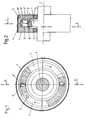
- Fig. 1 shows a first embodiment of the invention Rotary machine in cross section along the line I-I in Fig. 2 and Fig. 2 partially in Longitudinal section along the line II-II in Fig. 1.
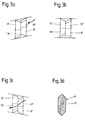
- Figs. 3A to 3C represent one of two parts existing slide in different positions of these two parts.
- Fig. 3D shows a Embodiment of a one-piece slide.
- Fig. 4 shows a cross section through a another embodiment along the line IV-IV in Fig. 5 and Fig. 5 shows a longitudinal section the line V-V in Fig. 4.
- Fig. 6 shows a third embodiment in cross section after the Line VI-VI in Fig. 7 and Fig. 7 is a longitudinal section along the line VII-VII in Fig. 6.
Abstract
Description
Die Erfindung betrifft eine Rotationskolbenmaschine mit wenigstens einem Gehäuse, das einen eine kreisförmige Grundform aufweisenden Kolben umschließt, wobei Gehäuse und Kolben relativ zueinander um eine durch den Kreismittelpunkt vertaufende Rotationsachse verdrehbar angeordnet sind, wobei eine Kolbenfläche und eine dieser zugewendete Gehäusewandfläche mit eine Kammer bildenden Ausnehmungen versehen sind und in zumindest einem Schlitz des Kolbens wenigstens ein zwangsgesteuerter, gegebenenfalls mehrteilig ausgebildeter Schieber derart verschiebbar geführt ist, daß er mit seinen Endflächen an einer Begrenzungswand der Ausnehmungen dichtend anlegbar ist.The invention relates to a rotary piston machine with at least one Housing which encloses a piston having a circular basic shape, wherein Housing and piston relative to each other around a through the center of the circle Rotation axis are arranged rotatably, a piston surface and one of these Provide facing housing wall surface with recesses forming a chamber are and in at least one slot of the piston at least one positively controlled, if necessary, multi-part slide is guided so that it with its end faces can be sealingly applied to a boundary wall of the recesses.
Derartige Rotationskolbenmaschinen sind bereits bekannt. Sie können sowohl als Motor, beispielsweise als Verbrennungskraftmotor und als hydraulisch und pneumatisch betriebener Motor, als Turbine, beispielsweise als Gas- oder Dampfturbine, und als Verdichter, beispielsweise als Luftverdichter, eingesetzt werden. In der Regel führt der Kolben innerhalb des feststehenden Gehäuses eine Drehbewegung aus, es ist aber auch möglich, das Gehäuse um den feststehenden Kolben rotieren zu lassen. Damit bei der Rotationsbewegung die zwischen der Kolbenoberfläche und der dieser zugewendeten Wandfläche des Gehäuses vorgesehene Kammer ihr Volumen verändert, was für den Verdichtungs- bzw. Expansionsvorgang erforderlich ist, kann sowohl die Wandfläche des Gehäuses als auch die dieser zugewendete Kolbenoberfläche in Bezug auf die Rotationsachse rotationsunsymmetrisch ausgebildet sein bzw. es können auch beide Flächen rotationsunsymmetrisch ausgebildet sein.Such rotary piston machines are already known. You can use both as Motor, for example as an internal combustion engine and as hydraulic and pneumatic powered engine, as a turbine, for example as a gas or steam turbine, and as Compressors, for example as air compressors, are used. As a rule, the Piston within the fixed housing a rotational movement, but it is also possible to rotate the housing around the fixed piston. So with the Rotational movement between the surface of the piston and the one facing it Wall area of the housing provided chamber changes its volume, which for the Compression or expansion process is required, both the wall surface of the Housing as well as the piston surface facing this in relation to the Rotation axis to be rotationally asymmetrical or both can be Surfaces are designed to be rotationally asymmetrical.
Es sind bereits Rotationskolbenmaschinen bekannt, bei welchen in einem Schlitz des Kolbens durch eine Nocke zwangsgesteuerte Schieber parallel zur Rotorachse verschiebbar angeordnet sind. Derartige Rotationskolbenmaschinen sind kompliziert in ihrem Aufbau. Bei einer anderen bekannten Rotationskolbenmaschine umfaßt der Rotor konzentrische Innen- bzw. Außenzylinder, einen umlaufenden Steg zur Verbindung dieser Zylinder und einen radial von der äußeren Oberfläche des Außenzylinders vorspringenden, umlaufenden Steg. Die Stege sind wellenförmig ausgebildet und die auf den gegenüberliegenden Seiten der Stege durch die Wellen entstehenden Hohlräume bilden die Arbeitskammern. Auch diese Ausführungsform ist äußerst kompliziert in ihrem Aufbau und schwierig herzustellen.Rotary piston machines are already known, in which in a slot the piston through a cam positively controlled slide parallel to the rotor axis are slidably arranged. Such rotary piston machines are complicated in their structure. In another known rotary piston machine, the rotor comprises concentric inner and outer cylinders, a circumferential web for connecting them Cylinder and a radially protruding from the outer surface of the outer cylinder, surrounding web. The webs are wave-shaped and those on the form opposite cavities on the opposite sides of the webs the working chambers. This embodiment is also extremely complicated in structure and difficult to manufacture.
Bei einer weiters bekannten Flügelzellenmaschine ist der Rotor mit einem einen Trennschieber tragenden Käfig versehen und exzentrisch gelagert, sodaß er eine Taumelbewegung ausführt.In a further known vane machine, the rotor is with one Slide cage bearing provided and eccentrically mounted so that it is a Wobbles.
Schließlich sind Rotationskolbenmaschinen bekannt, bei welchen in einem Gehäuse gelagerte Schieber vorgesehen sind. Finally, rotary piston machines are known, in which in a housing mounted slider are provided.
Eine Rotationskolbenmaschine gemäß der eingangs beschriebenen Art ist aus der DE-PS 631 254 bekanntgeworden. Die vorliegende Erfindung hat sich zur Aufgabe gestellt, eine derartige bekannte Rotationskolbenmaschine in ihrem konstruktiven Aufbau zu vereinfachen und die Funktionstüchtigkeit zu verbessern.A rotary piston machine according to the type described in the opening paragraph is from DE-PS 631 254 become known. The present invention has as its object such a known rotary piston machine in its construction simplify and improve the functionality.
Zur Lösung dieser Aufgabe schlägt die Erfindung vor, daß im Bereich jedes Schiebers und der zugehörigen Teile der Kolbenflächen jeweils eine Ausnehmung angeordnet ist und daß die Anzahl der Schieber der Anzahl der Ausnehmungen entspricht. Arbeitet beispielsweise die erfindungsgemäße Rotationskolbenmaschine als Motor, so findet Kompression und Verbrennung direkt in den Ausnehmungen statt, welchen somit das Gemisch direkt zugeführt wird bzw. aus welchem die verbrannten Gase direkt abgeführt werden können. Es sind also keine besonderen Vorkehrungen notwendig, durch welche Ansaugkanäle und Auslaßkanäle unterteilt werden, und durch die konstruktiv einfache Form werden die bei bekannten Konstruktionen auftretenden Dichtungsprobleme beseitigt. Bei Verwendung der erfindungsgemäßen Rotationskolbenmaschine als Verdichter dienen die Ausnehmungen als Kompressionskammern, bei Verwendung der erfindungsgemäßen Rotationskolbenmaschine als Gas- oder Dampfturbine gleichfalls als Verdichtungskammern, wodurch der Antrieb des rotierenden Teiles erfolgt.To achieve this object, the invention proposes that in the field of each Slider and the associated parts of the piston surfaces each have a recess is arranged and that the number of slides corresponds to the number of recesses. For example, if the rotary piston machine according to the invention works as a motor, then compression and combustion take place directly in the recesses, which therefore the Mixture is fed directly or from which the burned gases are removed directly can be. So no special precautions are necessary by which Intake ducts and exhaust ducts are divided, and by the simple design the sealing problems that occur in known constructions are eliminated. At Use of the rotary piston machine according to the invention as a compressor Recesses as compression chambers when using the invention Rotary piston machine as a gas or steam turbine as well Compression chambers, which drive the rotating part.
Die erfindungsgemäße Rotationskolbenmaschine kann verschiedenartig ausgebildet sein. Gemäß einer ersten Ausführungsform der Erfindung ist bzw. sind der bzw. die Schieber im Kolben parallel zur Rotationsachse verschiebbar und die Begrenzungswände der Ausnehmungen, an welchen die Endflächen der Schieber anliegen, weisen, gemessen von einer Normalebene zur Rotationsachse und parallel zur Rotationsachse, unterschiedliche Abstände auf, sodaß Kammern mit sich veränderndem Volumen gebildet werden.The rotary piston machine according to the invention can be designed in various ways be. According to a first embodiment of the invention, the is or are Slider in the piston can be moved parallel to the axis of rotation and the boundary walls of the recesses, on which the end faces of the slides bear, are measured from a normal plane to the axis of rotation and parallel to the axis of rotation, different distances, so that chambers with changing volumes are formed become.
Bei einer zweiten Ausführungsform der erfindungsgemäßen Rotationskolbenmaschine ist bzw. sind der bzw. die Schieber radial zur Rotationsachse verschiebbar und die Begrenzungswände der Ausnehmungen weisen von der kreisförmigen Grundform in radialer Richtung abweichende Abstände auf. Bei einer solchen Ausführungsform ist es möglich, daß der mit dem bzw. den Schieber(n) in einem funktionellen Zusammenhang stehende Teil des Kolbens, also jener Teil des Kolbens, in dem entweder der Schieber verschiebbar geführt ist, oder jener Teil, der die eine unsymmetrische Form aufweisende Fläche besitzt, an der der Schieber dichtend anliegt, die Form eines um die Rotationsachse rotierenden Hohlzylinders aufweist. Im letzteren Fall besitzt dieser Teil des Kolbens infolge der unsymmetrischen Form seiner Oberfläche allerdings nicht die Form eines Kreiszylinders, sondern weicht von der Kreisform ab. Eine derartige Ausführungsform ermöglicht es, an zwei einander gegenüberliegenden Seiten des die Form eines Hohlzylinders aufweisenden Kolbens Anlageflächen für den bzw. die Schieber vorzusehen, wodurch zu beiden Seiten dieses Hohlzylinders durch die Schieber begrenzte Kammern mit sich bei der Rotation veränderndem Volumen gebildet werden.In a second embodiment of the invention Rotary piston machine is or are the slide or radial to the axis of rotation slidably and the boundary walls of the recesses point from the circular Basic shape with different distances in the radial direction. With one Embodiment, it is possible that with the slider (s) in one Functionally related part of the piston, i.e. that part of the piston, in which either the slider is slidably guided, or that part that the one has an asymmetrical shape surface on which the slide rests sealingly, has the shape of a hollow cylinder rotating about the axis of rotation. In the latter case this part of the piston has due to the asymmetrical shape of its surface however not the shape of a circular cylinder, but differs from the circular shape. A Such embodiment allows two opposite sides of the the shape of a hollow cylinder piston bearing surfaces for the To provide sliders, whereby on both sides of this hollow cylinder through the slider limited chambers are formed with the volume changing during rotation.
Gemäß einer bevorzugten Ausführungsform der Erfindung ist die Anordnung so getroffen, daß der Schlitz bzw. die Schlitze sich zwischen gegenüberliegenden Seiten des Kolbens erstreckt bzw. erstrecken, und daß der Schieber bzw. die Schieber den Schlitz durchsetzt bzw. durchsetzen und an den beiden Enden mit Begrenzungswänden der Ausnehmungen zusammenwirken. In jedem Fall können hiebei beide aus den Durchgangsöffnungen herausragenden Enden der Schieber an unsymmetrisch ausgebildeten Gehäusewandflächen bei der Rotation des Kolbens anliegen, wobei diese Gehäusewandflächen natürlich gegengleich ausgebildet sein müssen, sodaß der Abstand zwischen den beiden unsymmetrisch ausgebildeten Gehäusewandflächen stets der Länge der Schieber entspricht. Es werden dann durch einen einzigen Schieber jeweils zwei an gegenüberliegenden Seiten des Kolbens vorgesehene, in ihrem Volumen veränderbare Kammern dichtend begrenzt.According to a preferred embodiment of the invention, the arrangement is like this hit that the slot or slots between opposite sides of the Piston extends, and that the slider or slides the slot enforced or enforce and at both ends with boundary walls Interact recesses. In any case, both of them can Through openings protruding ends of the slide at asymmetrical trained housing wall surfaces abut during the rotation of the piston, these Housing wall surfaces must, of course, be of opposite construction, so that the distance always the length between the two asymmetrically designed housing wall surfaces the slide corresponds. There are then two at a time by a single slider opposite sides of the piston provided, their volume can be changed Chambers sealed.
Die Schieber können einstückig und ohne irgendwelche Öffnungen ausgebildet sein, in welchem Fall die Schieber lediglich eine Abdichtung der von diesen Schiebern begrenzten Kammern bewirken, eine Verbindung zwischen solchen Kammern jedoch bei keiner Schieberstellung stattfindet. Häufig ist es jedoch erwünscht, daß bei bestimmten Schieberstellungen benachbarte Kammern miteinander verbunden werden sodaß ein Überströmen des in einer Kammer befindlichen Mediums in die benachbarte Kammer stattfindet. Um dies zu ermöglichen, kann bzw. können der Schlitz bzw. die Schlitze sich zwischen gegenüberliegenden Seiten des Kolbens erstrecken und der Schieber bzw. die Schieber durchsetzt bzw. durchsetzen den Schlitz und wirken an den beiden Enden mit Begrenzungswänden der Ausnehmungen zusammen.The slides can be made in one piece and without any openings, in which case the sliders only seal the of these sliders limited chambers, but a connection between such chambers no slide position takes place. However, it is often desirable that certain Slider positions adjacent chambers are connected to each other so that a Overflow of the medium in one chamber into the neighboring chamber takes place. In order to make this possible, the slot or slots can be extend between opposite sides of the piston and the slide or the Sliders penetrate or penetrate the slot and act on both ends Boundary walls of the recesses together.
Es kann aber auch der Schieber aus zwei relativ zueinander verschiebbaren Teilen bestehen, von welchen jeder mit einem Verbindungskanal versehen ist, wobei die Verbindungskanäle in den beiden Teilen so angeordnet sind, daß sie bei einer Änderung der Steigung der Begrenzungswände miteinander kommunizieren.However, the slide can also consist of two parts which can be displaced relative to one another exist, each of which is provided with a connecting channel, the Connection channels in the two parts are arranged so that they change the slope of the boundary walls communicate with each other.
In der Zeichnung ist die Erfindung anhand von Ausführungsbeispielen schematisch erläutert. Fig. 1 zeigt eine erste Ausführungsform der erfindungsgemäßen Rotationsmaschine im Querschnitt nach der Linie I-I in Fig. 2 und Fig. 2 teilweise im Längsschnitt nach der Linie II-II in Fig. 1. Die Fig. 3A bis 3C stellen einen aus zwei Teilen bestehenden Schieber in verschiedenen Lagen dieser beiden Teile dar. Fig. 3D zeigt eine Ausführungsform eines einteiligen Schiebers. Fig. 4 zeigt einen Querschnitt durch eine weitere Ausführungsform nach der Linie IV-IV in Fig. 5 und Fig. 5 einen Längsschnitt nach der Linie V-V in Fig. 4. Fig. 6 stellt eine dritte Ausführungsform im Querschnitt nach der Linie VI-VI in Fig. 7 und Fig. 7 einen Längsschnitt nach der Linie VII-VII in Fig. 6 dar. In the drawing, the invention is schematic using exemplary embodiments explained. Fig. 1 shows a first embodiment of the invention Rotary machine in cross section along the line I-I in Fig. 2 and Fig. 2 partially in Longitudinal section along the line II-II in Fig. 1. Figs. 3A to 3C represent one of two parts existing slide in different positions of these two parts. Fig. 3D shows a Embodiment of a one-piece slide. Fig. 4 shows a cross section through a another embodiment along the line IV-IV in Fig. 5 and Fig. 5 shows a longitudinal section the line V-V in Fig. 4. Fig. 6 shows a third embodiment in cross section after the Line VI-VI in Fig. 7 and Fig. 7 is a longitudinal section along the line VII-VII in Fig. 6.
Die in den Fig 1 und 2 dargestellte Rotationsmaschine weist einen Kolben 1 auf, der
um eine Rotationsachse 2 in einem aus zwei Teilen 3,4 bestehenden Gehäuse mittels
Wälzlagem 5 drehbar gelagert ist. Die beiden Gehäuseteile 3,4 sind über einen den
Umfang dieser Teile umgebenden Ring 6 dicht verbunden.The rotary machine shown in FIGS. 1 and 2 has a
Der Kolben 1 besteht bei dieser Ausführungsform aus einer Scheibe, in welcher sich
parallel zur Rotationsachse 2 erstreckende Schlitze 7 vorgesehen sind. In diesen Schlitzen
sind aus zwei relativ zueinander verschiebbaren Teilen 8',8'' bestehende Schieber 8
verschiebbar geführt, die in den Fig. 3A bis 3C in größerem Maßstab dargestellt sind. Die
beiden Enden dieser Schieberteile 8',8'' liegen an einer eine unsymmetrische Form
aufweisenden Begrenzungswand 9', 9'' an. Der Abstand dieser Begrenzungswände 9',9'' zu
einer Normalebene zur Rotationsachse 2 ändert sich entlang des Umfanges derart, daß
diese Begrenzungswände während des Umlaufes des Kolbens 1 zunächst an den
Kolbenflächen 10',10'' anliegen und dann über eine positive bzw. negative Steigung in
einen Bereich übergehen, wo diese Begrenzungswände in Abstand von den Kolbenflächen
10',10'' angeordnet sind. Die gegenseitige Lage der beiden Begrenzungswände 9',9'' muß
aber stets eine solche sein, daß die Enden der Schieberteile 8',8'' stets dichtend an diesen
Begrenzungswänden anliegen. Durch diese Ausbildung entstehen von den Schiebern
begrenzte Ausnehmungen 11 mit sich während der Rotation des Kolbens 1 änderndem
Volumen. Im Gehäuseteil 4 ist eine in eine solche Ausnehmung 11 mündende
Einlaßbohrung 12 vorgesehen, im Gehäuseteil 3 eine (nicht dargestellte) Auslaßbohrung.
Weiters ist bei Verwendung als Verbrennungskraftmotor an geeigneter Stelle eine
Zündvorrichtung angeordnet.The
Die Schieberteile 8',8'' werden durch die unsymmetrisch ausgebildeten Begrenzungswände 9',9'' zwangsgesteuert, wobei die Form derselben den Hubraum der Maschine bestimmen und der Grad der Steigung die Steuerzeit, den Zündzeitpunkt, den Gaswechsel, das Saugverhalten und anderes mehr beeinflußt.The slide parts 8 ', 8' 'are formed by the asymmetrical Boundary walls 9 ', 9' 'positively controlled, the shape of which the displacement of the Determine the machine and the degree of the slope, the timing, the ignition timing, the Gas changes that affect suction behavior and more.
Wird die in den Fig. 1 und 2 dargestellte Maschine als Verbrennungskraftmaschine betrieben, so wird durch die Ansaugöffnung 12 an der Rückseite eines aus den beiden Teilen 8',8'' bestehenden Schiebers ein Gas-Luftgemisch angesaugt. Die Ansaugöffnung befindet sich im Bereich einer Steigung der Begrenzungswände 9' bzw. 9'', sodaß die beiden Teile 8', 8'' die in Fig. 3A gezeigte Stellung einnehmen. In diesen Teilen befinden sich Verbindungskanäle 13',13'', die in dieser Stellung abgeschlossen sind.1 and 2 as an internal combustion engine operated, one of the two is through the suction opening 12 on the back Parts 8 ', 8' 'existing slider sucked a gas-air mixture. The suction opening is in the region of a slope of the boundary walls 9 'or 9' ', so that the both parts 8 ', 8' 'assume the position shown in Fig. 3A. Located in these parts connecting channels 13 ', 13' ', which are closed in this position.
Bewegt sich der Kolben 1 in Fig. 1 im Uhrzeigersinn, so wird das Gas-Luftgemisch in
die Ausnehmung gesaugt und dort gegen eine positive Steigung gedrückt sodaß eine
Verdichtung stattfindet. Die Abdichtung der Ausnehmung erfolgt durch die Schieberteile
8',8'' sowie durch Anliegen des Kolbens an den Wandflächen der Gehäuseteile 3,4. Die
beiden Schieberteile 8',8'' nehmen hier die in Fig. 3B dargestellte Lage ein, in der die
Verbindungskanäle 13', 13'' gleichfalls verschlossen sind. If the
Beim Auflaufen der Schieberteile 8',8'' gegen die positive Steigung des
Gehäuseteiles 4 werden diese Teile in die in Fig. 3C dargestellte Lage verschoben,
wodurch über die Verbindungskanäle 13',13'' eine Verbindung hergestellt wird, über die das
komprimierte Gas-Luftgemisch in die im Gehäuseteil 3 befindliche Ausnehmung 11 strömen
kann. Die Zeit, während welcher ein solches Überströmen erfolgt, wird durch die Länge der
Steigung bestimmt. Anschließend werden die Verbindungskanäle 13', 13'' wieder
verschlossen und unmittelbar danach findet am Höhepunkt der Kompression die Zündung
des Gas-Luftgemisches statt. Durch die Explosion wird der Kolben 1 in Richtung des
geringeren Widerstandes, also in Rotationsrichtung, verdreht, wobei das verbrannte Gas
zur Auslaßöffnung gefördert und dort abgeführt wird.When the slide parts 8 ', 8' 'run up against the positive slope of the
Durch diese Bauweise und Anordnung der Schieber können bei jeder vollen
Umdrehung des Kolbens 1 zwei volle Krafthübe durchgeführt werden.This design and arrangement of the slide can be full at any
Rotation of the
Anstelle des aus zwei Teilen 8', 8'' bestehenden Schiebers kann auch ein aus einem
einzigen Teil bestehender Schieber 8 vorgesehen sein, der mit einem Verbindungskanal 13
ausgestattet ist, wie dies in Fig. 3D dargestellt ist.Instead of the slide consisting of two parts 8 ', 8' ', a slide made of one
only part of existing
Die in den Fig. 1 und 2 gezeigte Maschine kann auch als Turbine und als Verdichter
für Druckluft, Dampf od.dgl. verwendet werden. In diesem Fall werden aus einem einzigen
Teil bestehende Schieber 8 verwendet, die keine Verbindungskanäle aufweisen. Über die
Einlaßbohrung 12 wird beispielsweise Druckluft zugeführt, die auf den Schieber 8 einwirkt
und dadurch den Kolben 1 in eine Drehbewegung versetzt und schließlich über eine
Auslaßöffnung wieder entweicht. Dieser Vorgang kann jeweils um beispielsweise 180°
versetzt in den zu beiden Seiten des Kolbens 1 vorgesehenen Ausnehmungen 11 erfolgen.The machine shown in FIGS. 1 and 2 can also be used as a turbine and as a compressor
for compressed air, steam or the like be used. In this case, a single
Partly existing
Soll die Maschine als Verdichter arbeiten, so wird der Kolben angetrieben, wodurch eine Kompression des zugeführten Gases erfolgt.If the machine is to work as a compressor, the piston is driven, thereby the supplied gas is compressed.
Die in den Fig. 4 und 5 dargestelle Ausführungsform unterscheidet sich von der
Ausführungsform nach den Fig. 1 und 2 dadurch, daß die aus den beiden Teilen 8',8''
bestehenden Schieber radial zur Rotationsachse 2 verschiebbar in einem Hohlzylinder 1'
geführt sind, der einen Teil des Kolbens 1 bildet. Die eine unsymmetrische Form
aufweisenden Flächen 9',9'' sind von Begrenzungswänden gebildet, die sich etwa parallel
zur Rotationsachse 2 erstrecken und welche die Zwangssteuerung der Schieberteile 8',8''
bewirken, welche an diesen Begrenzungswänden 9',9'' dichtend anliegen. Die
unsymmetrische Form dieser Begrenzungswände ist in Fig. 4 klar erkennbar. Auch bei
dieser Ausführungsform kann wieder anstelle des aus zwei Teilen bestehenden Schiebers
ein lediglich aus einem einzigen Teil bestehender Schieber 8 entsprechend Fig. 3D
verwendet werden. In Fig. 4 ist nicht nur die Einlaßöffnung 12, sondern auch die
Auslaßöffnung 14 ersichtlich.The embodiment shown in FIGS. 4 and 5 differs from that
Embodiment according to FIGS. 1 and 2 in that the two parts 8 ', 8' '
existing slide radially displaceable to the axis of
Bei Verwendung der in den Fig. 4 und 5 dargestellten Maschine als
Verbrennungskraftmaschine wird durch die Ansaugöffnung 12 an der Rückseite des aus
den Teilen 8',8'' bestehenden Schiebers ein Gas-Luftgemisch angesaugt. Die
Verbindungskanäle 13',13'' in den Schieberteilen 8',8'' sind hiebei verschlossen. Durch die
Drehbewegung des Kolbens 1 wird das Gas-Luftgemisch gegen die positive Steigung der
Begrenzungswand 9' gedrückt, wobei eine Verdichtung stattfindet. Wenn die Teile 8',8'' in
den Bereich dieser positiven Steigung gelangen, so werden sie derart gegeneinander
verschoben, daß die Verbindungskanäle 13',13'' miteinander fluchten, sodaß das
komprimierte Gas in die vom Gehäuseteil 3 begrenzte Ausnehnmung 11 überströmen kann,
wobei unmittelbar nach dem Verschließen dieser Verbindungskanäle 13',13'' bei 15 die
Zündung des Gas-Luftgemisches stattfindet. Durch die Explosion wird der Kolben 1 in
Drehrichtung bewegt und dabei das verbrannte Gas zur Auslaßöffnung 14 transportiert und
dort ausgeschoben. Der Verschluß der Einlaßöffnung 12 und der Auslaßöffnung 14 erfolgt
jeweils durch die Schieberteile 8',8'', wobei die beiden Schieber beim Ausführungsbeispiel
um jeweils 180° versetzt angeordnet sind, sowie durch jenen Bereich der
Begrenzungswände, der an den Kolbenflächen dichtend anliegt.When using the machine shown in Figs. 4 and 5 as
Internal combustion engine is made through the
In den Fig. 6 und 7 ist eine erfindungsgemäße Rotationsmaschine in ihrer
Verwendung als Turbine oder als Verdichter für Druckluft, Dampf od.dgl. dargestellt. Diese
Ausführungsform unterscheidet sich in konstruktiver Hinsicht von der in den Fig. 4 und 5
dargestellten Ausführungsform lediglich dadurch, daß einstückige Schieber 8 ohne
Verbindungskanal vorgesehen sind. Bei Verwendung als Turbine wird durch die
Einlaßöffnung 12 beispielsweise Druckluft zugeführt, die in die Ausnehmung 11 gelangt und
auf den Schieber 8 derart einwirkt, daß der Kolben 1 in Drehbewegung versetzt wird, bis
der Schieber 8 die im Gehäuseteil 4 vorgesehene Auslaßöffnung 14 überstreicht und die
Druckluft aus dieser Auslaßöffnung austritt. Auch über die im Gehäuseteil 3 vorgesehene,
gegenüber der Einlaßöffnung 12 um etwa 180° versetzte Einlaßöffnung 12' erfolgt eine
Druckluftzufuhr, die auf den Schieber 8 einwirkt und anschließend über die Auslaßöffnung
14' entweicht.6 and 7 is a rotary machine according to the invention in its
Use as a turbine or as a compressor for compressed air, steam or the like. shown. This
Embodiment differs in design terms from that in FIGS. 4 and 5
illustrated embodiment only in that one-
Wird die in den Fig. 6 und 7 dargestellte Maschine als Verdichter verwendet, so wird
das über die Einlaßöffnungen 12,12' zugeführte Gas durch den angetriebenen Kolben in
den Ausnehmungen 11 verdichtet, bevor es über die Auslaßöffnungen 14,14' austritt.If the machine shown in FIGS. 6 and 7 is used as a compressor, then
the gas supplied via the
Die Zeichnungen stellen nur den grundsätzlichen Aufbau der erfindungsgemäßen Maschine dar. Die erforderlichen konstruktiven Maßnahmen zur Erzielung der notwendigen Dichtheit sowie der Schmierung, Steuerung usw. sind nicht dargestellt und die Ausführung derselben ist mittels bekannter konstruktiver Maßnahmen vorzunehmen.The drawings represent only the basic structure of the invention Machine. The necessary constructive measures to achieve the necessary Tightness and lubrication, control, etc. are not shown and the execution the same is to be carried out by means of known constructive measures.
Claims (6)
Priority Applications (1)
| Application Number | Priority Date | Filing Date | Title |
|---|---|---|---|
| EP97890246A EP0921271A1 (en) | 1997-12-05 | 1997-12-05 | Rotary piston machine |
Applications Claiming Priority (1)
| Application Number | Priority Date | Filing Date | Title |
|---|---|---|---|
| EP97890246A EP0921271A1 (en) | 1997-12-05 | 1997-12-05 | Rotary piston machine |
Publications (1)
| Publication Number | Publication Date |
|---|---|
| EP0921271A1 true EP0921271A1 (en) | 1999-06-09 |
Family
ID=8231129
Family Applications (1)
| Application Number | Title | Priority Date | Filing Date |
|---|---|---|---|
| EP97890246A Withdrawn EP0921271A1 (en) | 1997-12-05 | 1997-12-05 | Rotary piston machine |
Country Status (1)
| Country | Link |
|---|---|
| EP (1) | EP0921271A1 (en) |
Citations (4)
| Publication number | Priority date | Publication date | Assignee | Title |
|---|---|---|---|---|
| DE631254C (en) * | 1933-11-17 | 1936-06-16 | Johannes Keller | Rotary piston internal combustion engine |
| US3902829A (en) * | 1974-04-04 | 1975-09-02 | David E Burrowes | Rotary power device |
| DE3222918A1 (en) * | 1982-06-18 | 1983-12-22 | Hans 7000 Stuttgart Bischoff | Combustion engine |
| DE4222000A1 (en) * | 1992-07-04 | 1992-11-05 | Josef Lipinski | Rotary-piston engine for vacuum, injection or diesel motors - has discs in separate housings on common shaft with central bearing and incorporating pistons |
-
1997
- 1997-12-05 EP EP97890246A patent/EP0921271A1/en not_active Withdrawn
Patent Citations (4)
| Publication number | Priority date | Publication date | Assignee | Title |
|---|---|---|---|---|
| DE631254C (en) * | 1933-11-17 | 1936-06-16 | Johannes Keller | Rotary piston internal combustion engine |
| US3902829A (en) * | 1974-04-04 | 1975-09-02 | David E Burrowes | Rotary power device |
| DE3222918A1 (en) * | 1982-06-18 | 1983-12-22 | Hans 7000 Stuttgart Bischoff | Combustion engine |
| DE4222000A1 (en) * | 1992-07-04 | 1992-11-05 | Josef Lipinski | Rotary-piston engine for vacuum, injection or diesel motors - has discs in separate housings on common shaft with central bearing and incorporating pistons |
Similar Documents
| Publication | Publication Date | Title |
|---|---|---|
| DE102005010775B3 (en) | Rotatable reciprocating engine for use as compressor, has two pistons revolving in housing, in which centrifugal forces arising due to revolution of pistons act in pivoting direction of pistons during revolution of pistons | |
| EP1856375B1 (en) | Oscillating piston engine | |
| EP1987232B1 (en) | Oscillating piston engine | |
| EP0240491B1 (en) | Rotary engine | |
| DE3150654C2 (en) | Rotary piston internal combustion engine | |
| EP0548297B1 (en) | Oscillating piston engine | |
| DE3528139C2 (en) | Internal combustion engine | |
| DE1426773A1 (en) | Rotary drive device | |
| DE2848220A1 (en) | ROTARY PISTON ENGINE | |
| EP0711379B1 (en) | Internal combustion engine with pistons that rotate around a centre line | |
| AT404159B (en) | Rotary piston machine | |
| WO2001036789A1 (en) | Rotating piston device | |
| EP0921271A1 (en) | Rotary piston machine | |
| DE3242505C2 (en) | Four-stroke rotary piston internal combustion engine | |
| DE10001962B4 (en) | Rotary piston engine | |
| EP0023529A2 (en) | Rotary piston machine of the external axis type | |
| DE3825372A1 (en) | Rotary engine | |
| DE4315155C2 (en) | Rotary lobe machine with periodically variable working chambers | |
| DE2611642A1 (en) | Rotary piston combustion engine - has pivoting sealing strip mounts and sickle shaped combustion chambers | |
| DE2522860A1 (en) | Rotary engine with elliptical working chamber - has sprung propulsion slides in rotor turning inside working chamber | |
| EP0826883B1 (en) | Rotary piston pump | |
| DE2416155A1 (en) | METHOD OF OPERATING AN INTERNAL COMBUSTION ENGINE AND OPERATING ENGINE PROCEDURE | |
| DE3820033A1 (en) | Internal combustion engine | |
| DE102020124450A1 (en) | rotary engine | |
| DE2258685A1 (en) | ROTARY PISTON ENGINE |
Legal Events
| Date | Code | Title | Description |
|---|---|---|---|
| PUAI | Public reference made under article 153(3) epc to a published international application that has entered the european phase |
Free format text: ORIGINAL CODE: 0009012 |
|
| AK | Designated contracting states |
Kind code of ref document: A1 Designated state(s): AT BE CH DE DK ES FI FR GB GR IE IT LI LU MC NL PT SE |
|
| AX | Request for extension of the european patent |
Free format text: AL;LT;LV;MK;RO;SI |
|
| AKX | Designation fees paid | ||
| REG | Reference to a national code |
Ref country code: DE Ref legal event code: 8566 |
|
| STAA | Information on the status of an ep patent application or granted ep patent |
Free format text: STATUS: THE APPLICATION IS DEEMED TO BE WITHDRAWN |
|
| 18D | Application deemed to be withdrawn |
Effective date: 19991210 |