EP0920221B1 - Bildverarbeitungsvorrichtung und -verfahren - Google Patents
Bildverarbeitungsvorrichtung und -verfahren Download PDFInfo
- Publication number
- EP0920221B1 EP0920221B1 EP98309537A EP98309537A EP0920221B1 EP 0920221 B1 EP0920221 B1 EP 0920221B1 EP 98309537 A EP98309537 A EP 98309537A EP 98309537 A EP98309537 A EP 98309537A EP 0920221 B1 EP0920221 B1 EP 0920221B1
- Authority
- EP
- European Patent Office
- Prior art keywords
- color
- pixel
- pixels
- image
- blur
- Prior art date
- Legal status (The legal status is an assumption and is not a legal conclusion. Google has not performed a legal analysis and makes no representation as to the accuracy of the status listed.)
- Expired - Lifetime
Links
- 238000012545 processing Methods 0.000 title claims abstract description 140
- 238000000034 method Methods 0.000 title claims description 12
- 238000009499 grossing Methods 0.000 claims abstract description 85
- 238000004364 calculation method Methods 0.000 claims abstract description 46
- 230000008859 change Effects 0.000 claims description 29
- 230000002093 peripheral effect Effects 0.000 claims description 20
- 238000001514 detection method Methods 0.000 claims description 19
- 239000007787 solid Substances 0.000 claims description 10
- 238000012986 modification Methods 0.000 claims description 8
- 230000004048 modification Effects 0.000 claims description 8
- 238000001914 filtration Methods 0.000 claims description 4
- 238000003672 processing method Methods 0.000 claims description 4
- 230000000694 effects Effects 0.000 claims 2
- 230000001502 supplementing effect Effects 0.000 claims 2
- 230000014509 gene expression Effects 0.000 description 22
- 238000001444 catalytic combustion detection Methods 0.000 description 17
- 238000010586 diagram Methods 0.000 description 13
- 239000011159 matrix material Substances 0.000 description 13
- 238000004088 simulation Methods 0.000 description 9
- 238000010276 construction Methods 0.000 description 7
- 230000008569 process Effects 0.000 description 5
- 230000009467 reduction Effects 0.000 description 5
- 239000003086 colorant Substances 0.000 description 4
- 230000001174 ascending effect Effects 0.000 description 3
- 230000008901 benefit Effects 0.000 description 3
- 238000004891 communication Methods 0.000 description 3
- 238000007796 conventional method Methods 0.000 description 3
- 238000006243 chemical reaction Methods 0.000 description 2
- 230000010354 integration Effects 0.000 description 2
- 230000000873 masking effect Effects 0.000 description 2
- 238000012935 Averaging Methods 0.000 description 1
- 230000007423 decrease Effects 0.000 description 1
- 238000009792 diffusion process Methods 0.000 description 1
- 230000003287 optical effect Effects 0.000 description 1
- 239000004065 semiconductor Substances 0.000 description 1
Images


Classifications
-
- H—ELECTRICITY
- H04—ELECTRIC COMMUNICATION TECHNIQUE
- H04N—PICTORIAL COMMUNICATION, e.g. TELEVISION
- H04N23/00—Cameras or camera modules comprising electronic image sensors; Control thereof
- H04N23/80—Camera processing pipelines; Components thereof
- H04N23/84—Camera processing pipelines; Components thereof for processing colour signals
- H04N23/843—Demosaicing, e.g. interpolating colour pixel values
-
- H—ELECTRICITY
- H04—ELECTRIC COMMUNICATION TECHNIQUE
- H04N—PICTORIAL COMMUNICATION, e.g. TELEVISION
- H04N25/00—Circuitry of solid-state image sensors [SSIS]; Control thereof
- H04N25/10—Circuitry of solid-state image sensors [SSIS]; Control thereof for transforming different wavelengths into image signals
- H04N25/11—Arrangement of colour filter arrays [CFA]; Filter mosaics
- H04N25/13—Arrangement of colour filter arrays [CFA]; Filter mosaics characterised by the spectral characteristics of the filter elements
- H04N25/134—Arrangement of colour filter arrays [CFA]; Filter mosaics characterised by the spectral characteristics of the filter elements based on three different wavelength filter elements
-
- H—ELECTRICITY
- H04—ELECTRIC COMMUNICATION TECHNIQUE
- H04N—PICTORIAL COMMUNICATION, e.g. TELEVISION
- H04N2209/00—Details of colour television systems
- H04N2209/04—Picture signal generators
- H04N2209/041—Picture signal generators using solid-state devices
- H04N2209/042—Picture signal generators using solid-state devices having a single pick-up sensor
- H04N2209/045—Picture signal generators using solid-state devices having a single pick-up sensor using mosaic colour filter
- H04N2209/046—Colour interpolation to calculate the missing colour values
Definitions
- the present invention relates to an image processing apparatus which performs image processing on image data obtained by utilizing a single-plate solid image pickup device and an image processing method.
- a digital still camera or the like using a solid image pickup device usually employs a single-plate method.
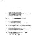
- Fig. 23 (a) in the single-plate method, color filters of R (red), G (green) and B (blue) are arranged in mosaic at predetermined ratios, in correspondence with respective pixels of the solid image pickup device.
- G color filters are zigzag arranged, in a high color component ratio.
- color signals of the respective R, G and B colors cannot be obtained, but only one of R, G and B color signals is obtained. Accordingly, color signals that cannot be directly obtained at each pixel are obtained by interpolation from color signals of adjacent pixels, then all the R, G and B color signals are converted into multilevel data.
- the multilevel data are outputted, and display is made based on the multilevel data on a display device or the like.
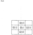
- Fig. 23(a) in the intermediate color filter array indicated by an arrow ( ⁇ ), the left half part from the center is irradiated with light (white part), while the right half part from the center is not irradiated with light (hatched part), as shown in Fig. 23(b) .
- the color signal level of respective colors in irradiated state is "1" and that of the same color signals in unirradiated state is "0”
- the levels of the R and G color signals will have values as shown in Fig. 23(c) .
- a G color signal cannot be directly obtained from an R color filter, and an R color signal cannot be directly obtained from a G color filter. Accordingly, the G color signal corresponding to the R color filter is obtained from linear interpolation on the G color signal at an adjacent pixel. On the other hand, the R color signal corresponding to the G color filter is obtained from linear interpolation on the R color signal at an adjacent pixel. Then, the G and R color signal levels have the values as shown in Figs, 23 (d) and 23 (e) . As it is apparent from these figures, false color signals occur at pixels around the boundary between an irradiated area and an unirradiated area, and a color blur occurs on an image by this false color signal.
- a smoothing filter (low-pass filter) is applied to color difference data of all the pixels constituting image data so as to make the color blur inconspicuous.
- the conventional technique has the following problem.
- United States Patent No. 5,552,827 issued on 3rd September 1996 , describes a color video camera, which includes a CCD, and in which digital signals of four lines produced on the basis of an output from the CCD are applied to a selection circuit, which selectively outputs digital signals of three lines.
- a horizontal interpolation circuit and a vertical interpolation circuit perform interpolation calculation on the basis of the digital signals, and outputs a plurality of horizontal color signals and a plurality of vertical color signals, respectively.
- a horizontal correlation detection circuit and a vertical correlation detection circuit evaluate a horizontal correlation value and a vertical correlation value of a specific pixel with respect to pixels around the specific pixel.
- Horizontal and vertical weighting coefficients are calculated by a coefficient calculation circuit in accordance with the correlation values, and the coefficients are applied to a weighted addition circuit, which adds the horizontal color signals and the vertical color signals to each other for each color in accordance with the coefficients, and outputs the color signals of the specific pixel.
- the processing described in this patent takes into account a pixel of interest and its correlation with surrounding pixels in order to prevent the generation of a false color. However, it does not involve additional processing for removing color blur after the interpolation process.
- the present invention has been made in consideration of the problem described earlier, and has as its object to provide an image processing apparatus, which reduces processing time, upon reduction of color blur in image data obtained by a single-plate solid image pickup device, and an image processing method.
- the present invention is constructed as above on the premise that image data as an image processing object consists of dot-matrixed pixels obtained by a single-plate solid image pickup device.
- the single-plate solid image pickup device as color filters of a plurality of element colors are arranged in mosaic in nonuniform densities, the element colors are supplemented by calculation so as to obtain uniform densities.
- a false color component is generated upon calculation and a color blur occurs.
- the color-blur pixel detection unit detects a color blur pixel where such color blur occurs, and the image processing unit performs image processing on pixels within a predetermined range having the detected color blur pixel as a reference, to reduce the color blur.
- a color blur pixel is detected, and the color blur is reduced with respect to pixels within a predetermined range having the detected pixel as a reference. Accordingly, an image processing apparatus which reduces the amount of calculation and reduces processing time can be provided.
- the image processing apparatus which detects a color blur pixel and reduces a color blur with respect to pixels within a predetermined range having the color blur pixel as a reference, may be a single device or may be installed into another apparatus.
- the present invention may be utilized in various aspects. Further, the present invention can be appropriately changed; for example, it can be realized by hardware or software.
- the idea of the present invention exists, and can be utilized on a storage medium containing the software.
- the storage medium may be a magnetic storage medium or opto-magnetic storage medium, or any storage medium developed in the future; further, duplications from such storage medium such as a primary duplicate, a secondary duplicate and the like must be equivalent to the initial storage medium.
- a communication line is used as unit for supplying the present invention, or even if the method of the present invention is written into a semiconductor chip, the present invention can be utilized.
- the idea of the present invention does not change even if it is realized partially by software and partially by hardware, and further, partially stored on a storage medium and appropriately read out from the storage medium in accordance with necessity.
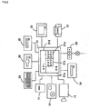
- Fig. 1 is a block diagram showing an image processing system to which an image processing apparatus according to an embodiment of the present invention is applied.
- Fig. 2 is a block diagram showing a particular hardware construction of the apparatus.
- an image input device 10 outputs an image obtained by utilizing a single-plate CCD or the like, as image data represented by dot-matrixed pixels, to an image processing apparatus 20.
- the image data obtained by the single-plate CCD includes a color blur.
- the image processing apparatus 20 detects a color blur pixel in the input image data, then performs image processing within a predetermined range having the color blur pixel as a reference so as to reduce the color blur, and outputs the processed data to an image output device 30.
- the image output device 30 outputs the image processed data in dot-matrixed pixels.
- the image processing apparatus 20 comprises color-blur pixel detection unit for detecting a color blur pixel, and image processing unit for performing image processing to reduce the color blur with the detected color blur pixel as a reference.
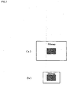
- the image input device 10 is realized by, e.g., in Fig. 2 , a film scanner 11 a digital still camera 12 or a video camera 14 having a single-plate CCD.
- Fig. 3 is a schematic diagram showing a schematic hardware construction of the digital still camera 12.
- incident light passes through an optical system 12a and enters a CCD 12b.
- the CCD 12b has R, G and B color filters arranged at predetermined ratios in correspondence with the respective pixels.
- a driver 12c outputs color signals at each pixel.
- the output color signals are digital-converted and inputted into an interpolation calculator 12d.
- the interpolation calculator 12d obtains a color signal of an element color component, which cannot be directly obtained with respect to a pixel, by linear interpolation calculation from a peripheral pixel.
- the color signals including the signal obtained by the linear interpolation are stored as RGB multilevel data into an image memory 12e.
- the image processing apparatus 20 is realized by, e.g., a computer system comprising a computer 21, a hard disk 22, a keyboard 23, a CD-ROM drive 24, a floppy disk drive 25 and a modem 26.
- the image output device 30 is realized by, e.g., a printer 31 or a display 32.
- the modem 26 is connected to a public communication line, and connected to an external network via the public communication line, to download and introduce software and data.
- the film scanner 11 or the digital still camera 12 as the image input device 10 outputs RGB multilevel data as image data
- the printer 31 as the image output device 30 inputs CMY (cyan, magenta, yellow) or CMYK (CMY + black (K)) binary data, while the display 32 inputs RGB multilevel data.
- an operating system 21a operates in the computer 21, and a printer driver 21b and a display driver 21c corresponding to the printer 31 and the display 32 are installed in the computer 21. Further, an image processing application program 21d performs processing under the control of the operating system 21a. The image processing application program 21d performs predetermined image processing in cooperation with the printer driver 21b and the display driver 21c, in accordance with necessity.
- the computer 21 as the image processing apparatus particularly plays roles to input RGB multilevel data, generate RGB multilevel data where image processing has been performed to detect a color blur pixel and reduce the color blur, display the data on the display 32 via the display driver 21c, and at the same time, convert the data into CMY (or CMYK) binary data via the printer driver 21b, and cause the printer 31 to print-output the converted data.
- a computer system for image processing is installed between the image input and output devices, however, such computer system is not necessarily provided.
- the present invention is applicable to a system to perform image processing to reduce a color blur with respect to image data including the color blur, resulted from image-pickup by a single-plate CCD and interpolation calculation as described above.
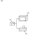
- the present invention may be applied to a system where an image processing apparatus to perform image processing is installed into a digital still camera 13a having a single-plate CCD.
- a display 32a performs display or a printer 31a performs printing by using image data where a color blur is reduced.
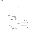
- the system may be constructed such that a printer 31b which inputs image data without computer system and perform printing, performs image processing to image data, inputted via a film scanner 11b or a digital still camera 13b having a single-plate CCD, to reduce a color blur.
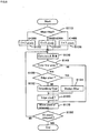
- the above-described image processing to detect a color blur pixel and to reduce a color blur is executed by an image processing program, corresponding to a flowchart of Fig. 6 , in the above computer 21.
- the method for reducing a color blur employed in the present embodiment uses a smoothing filter as described later, similarly to the conventional method, however, it is different from the conventional method in that the range where the smoothing filter is used is limited to periphery of a color blur pixel.
- smoothing processing on two image sizes of bit maps as image data to be processed as shown in Figs. 7(a) and 7(b) , is considered.
- the image data are processed with smoothing filters of the same size, as represented by hatched portions in the figures.
- each pixel of the image data one-to-one corresponds to each pixel of a CCD
- the image size differs in accordance with the number of pixels of the CCD; further, even if the number of pixels of the CCDs are the same, the image size is appropriately enlarged/reduced.
- the image data in this case have different sizes from these reasons.
- the present embodiment employs smoothing filters of different sizes of, e.g., 3 ⁇ 3, 5 ⁇ 5 and 7 ⁇ 7, as shown in Figs. 8(a) to 8(c) , and appropriately selects the smoothing filter in accordance with an image size.
- (height) ⁇ (width) of the image may be calculated to obtain the number of pixels, and the obtained number of pixels may be used as an index.
- step S110 if A ⁇ 300 holds, the 3 ⁇ 3 pixel smoothing filter is selected; if 300 ⁇ A ⁇ 600 holds, the 5 ⁇ 5 pixel smoothing filter is selected; and if A > 600 holds, the 7 ⁇ 7 pixel smoothing filter is selected.
- the types of smoothing filters used at steps S122 to S126 are stored into a work area.
- the work area may be a RAM in the computer 21 or the hard disk 22.
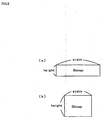
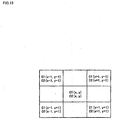
- the min (height, width) is used as a reference from the following reason. That is, whether or not the size of a smoothing filter is appropriate may be determined based on the ratio of the number of smoothed pixels with respect to the number of all the pixels. However, there are various image data, even having the same number of pixels, such as image data having a width longer than its length, as shown in Fig. 9 (a) , and a typical rectangular image data having a width a little longer than its length as shown in Fig. 9 (b) . In a case where a smoothing filter is determined in accordance with the number of pixels of processing object image, the same smoothing filter is selected for both image data in Figs. 9(a) and 9(b) .
- the former image is smoothed almost over the whole length in height, although the latter image is smoothed with an appropriate smoothing filter.
- the former image provides visually blurred impression. Accordingly, this inconvenience can be avoided by using smaller one of the "height" and "width" of image as a reference.
- each pixel is represented by RGB multilevel data ("0" to "255” level) .
- the types of the smoothing filters to be used are stored at steps S122 to S126, then, at step S130, the difference ⁇ RB of R and B multilevel data at a pixel of interest and its peripheral pixel.
- the CCD of the present embodiment has an arrangement where the R, G and B color filters are arranged in mosaic in correspondence with respective pixels, and only the G color filters are zigzag arranged in a high density, while the R and B color filters are arranged in low densities.
- a color signal which cannot be directly obtained is obtained by linear interpolation calculation from a color signal of an adjacent pixel, then the obtained the R, G and B color signals are converted into multilevel data. Accordingly, as a result of linear interpolation calculation, at some pixel, lack of initial intensity in low-density R, B multilevel data, or generation of false element color component which has not been initially unnecessary, causes a color blur, at a certain probability.
- the G color filters are arranged in a high density, there is a low probability that a false G color component occurs from interpolation calculation; the R component, that can be usually directly obtained from the G color filter, does not include a false color component.
- the value of the difference ⁇ RB is "0"
- the value of the difference ⁇ RB is also "0"
- the value of the difference ⁇ RB tends to be greater than "0".
- a pixel where the R and G components have high intensities while the B component has a low intensity exists.
- the respective element color components are maintained at its adjacent pixel, and the ⁇ RB value gradually changes as it becomes distant from the initial pixel.
- a color blur basically occurs in pixel units, and one of adjacent pixels is white or black or the like, it cannot be wrong to regard a pixel having a high ⁇ RB change rate between adjacent pixels as a color blur pixel.
- the change rate of the ⁇ RB value between a pixel of interest and its peripheral pixel is examined as described later, and a pixel having a high change rate is detected as a color blur pixel.
- the examination of the ⁇ RB change rate can be preferably made by comparing the ⁇ RB change rate between pixels corresponding to (low-density color filters. That is, as a false element color component frequently occurs at a pixel corresponding to a low density color filter in comparison with a pixel corresponding to a high density color filter, the comparison of the ⁇ RB change rate between pixels corresponding to low density color filters enables detection with higher reliability.
- step S140 Actual color-blur pixel detection is performed at step S140, where it is determined whether or not a pixel of interest is a color blur pixel based on the change rate of the difference ⁇ RB, obtained as above, between peripheral pixels.
- a matrix having x pixels in a horizontal direction and y pixels in a vertical direction is considered with the pixel of interest as a central pixel.
- E 4 ⁇ ⁇ RB x y - 2 ⁇ ⁇ RB ⁇ x - 1 , y - 1 - 2 ⁇ ⁇ RB ⁇ x + 1 , y - 1
- the value of E and a predetermined threshold value Th is compared.
- E ⁇ Th holds, it is determined that the pixel of interest is a color blur pixel. Accordingly, at the above-described step S130, the difference ⁇ RB at the pixel of interest is obtained, and ⁇ RB(x-1, y-1) and ⁇ RB(x+1, y-1) are obtained as ⁇ RB values of peripheral pixels.
- the meaning of the detection of the color blur pixel in accordance with the determination reference E ⁇ Th is as follows. That is, if a color blur has occurred at a pixel of interest, as the ⁇ RB value change rate between the pixel of interest and its peripheral pixel becomes high, the value E in the equation (5) is large. If the value E exceeds the threshold value Th, it is determined that the pixel of interest is a color blur pixel. Further, referring to the equation (5) and Fig. 11 , the ⁇ RB value change rate is examined between the pixel of interest and its diagonally adjacent pixel. Referring to Fig.
- the color-blur pixel detection is made based on the change rate of the difference between element color intensities corresponding to low-density color filters.
- Color-blur pixel detection unit is constructed by hardware and software to execute the above detection.
- step S140 If it is determined at step S140 that the pixel of interest is a color blur pixel, it is determined whether or not the pixel is an edge pixel at step S150.
- edge pixel As the determination of edge pixel is effectively made based on color difference component, color difference components C1 and C2 are obtained by subtracting a luminance component Y from R and B multilevel data, in the present embodiment.
- the change rate of the color difference components C1 and C2 are high between adjacent pixels. If any one of the following two determination references is satisfied, a pixel of interest is determined to be an edge pixel.
- the expressions (9) and (10) mean that, in image data consisting of dot-matrixed pixels having a color blur pixel as a central pixel as shown in Fig. 12 , the change rates of the color difference components C1 and C2 are obtained between orthogonally adjacent pixels, and it is respectively determined whether or not the color difference components are greater than the threshold values Th1 and Th2. If one of the determination references is satisfied, the pixel of interest is determined to be an edge pixel. As the pixels are arranged in matrix as shown in Fig. 13 , and when the central pixel is treated as a pixel of interest, there are eight adjacent pixels. Similarly, the change rates of the color difference components C1 and C2 obtained between adjacent pixels, and compared with threshold values Th1 and Th2. If the color difference components C1 or C2 is equal to or greater than the threshold value Th1 or Th2, it may be determined that the pixel of interest is a color blur pixel.
- the determination as to whether or not the color blur pixel is an edge pixel is effectively made based on the change rates of the color difference components C1 and C2.
- comparison using the color difference components C1 and C2 are respectively performed with respect to eight adjacent pixels, the amount of calculation is too large, which might lower the processing speed. Accordingly, the comparison calculation may be performed with respect to four pixels in vertical and horizontal directions as shown in Fig. 14 , or the comparison calculation may be performed with respect to diagonally adjacent four pixels as shown in Fig. 15 . These methods reduces the amount of calculation.
- the determination as to whether the color blur pixel is an edge pixel may be made based on the slope of luminance.
- the above-described expressions (9) and (10) are replaced with the following expression: Y x y - Y ⁇ x - 1 , y - 1 ⁇ Th ⁇ 3
- step S150 If it is determined at step S150 that the color blur pixel is not an edge pixel, the process proceeds to step S152 at which smoothing processing is performed using the smoothing filter determined at steps S122 to S126 with respect to pixels within a predetermined range having the color blur pixel as a reference.
- step S152 Upon execution of smoothing processing, as smoothing of color difference component is effective, the smoothing processing is performed on the color difference components C1 and C2, calculated in accordance with the above equations (6) and (7), in the present embodiment.
- the central value is used as a weight on the color difference components C1 and C2 of a pixel of interest in the matrix image data.
- the value is used for integration with respect to peripheral pixels of the pixel of interest with weighting corresponding to values of the cells of the smoothing filter.
- every cell has a value "1"
- a smoothed color difference component C1' is obtained by adding up the color difference components C1 of the respective cells and dividing by the number of the cells; a smoothed color difference component C2' is similarly obtained.
- the respective cells may have appropriate weights respectively.
- smoothing filter means execution of the above-described matrix calculation, and therefore, if the respective cells have weights, the amount of calculation increases. That is, in the present embodiment, as the respective cells of the smoothing filters have the value "1", the data of the respective pixels may be added up and divided by the number of cells. However, in a case where the respective cells have weights, multiplication and addition are required for the number of cells, which increases the amount of calculation.
- the processing of the present embodiment to detect a color blur pixel and perform smoothing around the color blur pixel is expected to greatly -reduce the amount of calculation, and enable high-speed image processing.
- step S150 determines whether the color blur pixel is an edge pixel.
- the process proceeds to step S154 at which a 5 ⁇ 5 pixel median filter is applied to pixels having the color blur pixel as the central pixel.
- the size of actually-used median filter is not necessarily 5 ⁇ 5 pixel size, but may be 3 ⁇ 3 pixel size. Thus, the size of the median filter may be appropriately selected. Then, for convenience of explanation, a case using a 3 ⁇ 3 pixel median filter will be described.
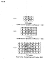
- a 3 ⁇ 3 pixel dot matrix having a color blur pixel as the central pixel is considered.
- the values of the respective cells are values of the color difference components C1.
- the diagonal line in Fig. 16 corresponds to an edge direction.
- Using the 3 ⁇ 3 pixel median filter means sorting the values of the color difference components C1 of the all nine pixels in ascending or descending order, selecting the central value and replacing the value with the value of the color difference component C1 of the color blur pixel. That is, in Fig. 16 , six pixels have "10" C1 values, one pixel has "40" C1 value, and three pixels have "100” C1 values. If these values are sorted in ascending order, the result is as shown in Fig. 17 . It is apparent from Fig. 17 , the central value is "10", and the value of the color difference component C1 of the color blur pixel is "10".
- the value of the smoothed color difference component C1' is "33", obtained from dividing the total value "300" of the cell values by the number of pixels "9".
- the smoothed color difference component C1' is obtained by averaging and adding up the color difference components C1 of the peripheral pixels of the color blur pixel, the image data is smoothed.
- the result of smoothing is equivalent to the result of so-called low-pass filtering.
- the image is smoothed and the color blur is inconspicuous, however, edge portions are inconveniently vague.
- the application of the median filter to the edge pixel avoids blur of the edge portion.
- a color blur occurs at a pixel where the value of the color difference component C1 is "40". It is understood that if the 3 ⁇ 3 pixel median filter is applied to this color blur pixel, as the value of the seven color difference components of the eight peripheral pixels is "100" and the value of the color difference component of the only one pixel is "10", the value of the color difference component of the color blur pixel is replaced with "100", thus the color blur is reduced. In this manner, the median filter also has an advantage to reduce a color blur while avoiding blurring an edge portion. For this reason, it is determined whether or not the color blur pixel is an edge pixel at step S150.
- the median filter has a 3 ⁇ 3 pixel size, however, if a 5 ⁇ 5 pixel median filter is used in the present embodiment, similarly to the case of the 3 ⁇ 3 pixel median filter, the central value can be selected from the total twenty-five pixels. Further, only the color difference components C1 have been described, however, the color difference components C2 may be similarly treated.
- the calculation speed using the median filter is relatively lower than that using the smoothing filter. Accordingly, it is preferable that the use of median filter is avoided as much as possible.
- the expressions (9) and (10) are employed as the edge-pixel determination references, one of these expressions is satisfied on some occasions, and both expressions are satisfied on some occasions. If one of the expression is satisfied, it is not necessary to use the median filter with respect to the both color difference components. Further, to avoid reduction of processing speed, the median filter is used only with respect to the color difference component which satisfies the expression at step S154, while the smoothing filter is used with respect to the other color difference component at step S152. This entirely improves the processing speed.
- the median filter is applied to both color difference components C1 ad C2 at step S154.
- edge enhancement processing is performed at step S160.
- "Yunsharp" represents unsharp masking processing on image data of a color blur pixel.
- unsharp masking processing will be described.
- three types of 3 ⁇ 3 pixel unsharp mask, 5 ⁇ 5 pixel unsharp mask and 7 ⁇ 7 pixel unsharp mask are prepared, in correspondence with the sizes of the smoothing filters determined at steps S122 to S126.
- This value is the total value of the cell values in the respective smoothing filters of the different sizes. That is, in the 5 ⁇ 5 pixel filter, this value is "400"; and in the 7 ⁇ 7 pixel filter, this value is "900".
- "Mij” represents a weighting coefficient set in the unsharp mask cells.
- Y(x,y) represents a luminance component at each pixel. Further, “ij” is represented by horizontal and vertical coordinate values with respect to the unsharp mask.
- Yunsharp (x, y) is obtained by adding the values of peripheral pixels with lowered weights with respect to a color blur pixel, it is also equivalent to low-pass filtered result. Accordingly, “Y(x,y)-Yunsharp (x, y) " is equivalent to subtraction of low frequency components from all the components, i.e., high-pass filtering. Then, the high-pass filtered high frequency components are added to "Y(x,y)", i.e., the high frequency components are increased. Thus, the edge is enhanced and the image sharpness is improved.
- the weight coefficient becomes the greatest at the central portion, and gradually decreases towards the periphery. Accordingly, the weighting coefficients at the periphery have small influence on the total of the cell values.
- the matrix calculation represented by the expression (13) or the like as multiplication and addition are required for the number of cells of the used unsharp mask with respect to the peripheral pixels of a pixel of interest, the amount of calculation may be considerably great. Accordingly, in the present embodiment, the amount of calculation is reduced and the processing speed is increased-by using 3 ⁇ 3 pixel, 5 ⁇ 5 pixel and 7 ⁇ 7 pixel unsharp masks where peripheral weighting coefficients are omitted.
- the size of the smoothing filter and that of the unsharp mask are the same from the following reason.
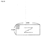
- a bitmap image as shown in Fig. 19 a hatched area is smoothing processed, then an area surrounded by a broken line is unsharp masked for luminance enhancement.
- luminance enhancement is compensation for sharpness lost by smoothing processing, if the luminance is enhanced even outside of the smoothing area, the sharpness may be unnaturally improved outside of the smoothing area.
- the size of the smoothing filter and that of the unsharp mask are the same, however, the latter size may be smaller than the former size.
- step S160 edge enhancement processing as described above is performed, and R', G' and B' multilevel data are obtained based on the equations (6) to (8) using the enhanced luminance Y' and the processed color difference components. That is, the color blur is reduced at steps S152 and S154, and multilevel data is generated at step S160.
- the hardware construction and software to execute the above processings construct the image processing unit.
- step S160 occasionally the R', G' and B' multilevel data have negative values, or the values are over "255", due to use of the enhanced luminance Y'. However, as the multilevel width ranges from “0" to "255”, negative multilevel data are uniformly changed to "0”, and multilevel data over "255" are uniformly changed to "255”.
- step S170 the pixel of interest is moved, and similar processing is repeated until it is determined at step S180 that all the pixels have been processed.
- the smoothing filter is applied to pixels with a color blur pixel as the central pixel and then the edge enhancement processing is performed, the color blur is reduced by the smoothing processing, and the image sharpness lost by the smoothing processing is compensated by the edge enhancement processing. Accordingly, the above processings may be uniformly performed on all the color blur pixels whether the color blur pixel is an edge pixel or not, and similar advantages can be attained by this arrangement. In the above construction, empirically, as the edge portion is occasionally blurred, it is arranged such that the median filter is used if the color blur pixel is an edge pixel, to obtain excellent result.
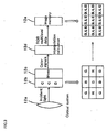
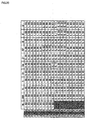
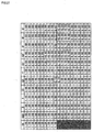
- Fig. 20 is a table showing various parameter values in a one-dimensional simulation model in a case where edge enhancement processing is not performed.
- the left end R, G and B matrix corresponds to the color filter arrangement of a CCD.
- "IN" on the right side of the matrix indicates light incidence state. If the value is "1 (multilevel data value is "255")", it indicates light-irradiated state, i.e., "white”. If the value is "0 (the value of multilevel data value is "0”)", it indicates "black”.
- a color signal which cannot be directly obtained is obtained from a color signal of an adjacent pixel by linear interpolation calculation.
- the simulation model should be two-dimensionally arranged, however, the central vertical array in the above RGB matrix is taken out for convenience of explanation. In this meaning, the array is referred to as a one-dimensional simulation model.
- the pixels where the false color signals have occurred are detected as color blur pixels.
- the color difference components C1 and C2 are calculated in accordance with the equations (6) to (8), then the color difference components C1 and C2 are smoothing processed and color difference components C1' and C2' are obtained.
- the values "1, 1, 1, 1, 1, 1” are used as a one-dimensional smoothing filter. That is, the values of three pixels above the pixel of interest and the values of three pixels below the pixel of interest are added up and divided by "7". Then, the obtained color difference signals C1' and C2' are returned to the initial color signals based on the equations (6) to (8), and smoothing processed R', G' B' are obtained. As it is apparent from the figure, “(R', G', B')” at pixels around the border between the white and black areas are respectively, “(0.75, 0.61, 0.61)” and “(0.25, 0.11, 0.11)", closer to the initial "IN” values. Thus, the color blur is reduced.
- Fig. 21 is a table showing various parameter values in the one-dimensional simulation model in a case where smoothing processing is performed and edge enhancement processing is performed using the unsharp mask of the same size of the smoothing filter.
- the color difference components C1 and C2 are obtained and the smoothing processing is performed.
- a one-dimensional unsharp mask having weighting coefficients "1, 6, 18, 25, 18, 6, 1" is utilized to use the enhanced luminance signal Y'.
- Fig. 22 is a table showing various parameter values in the on-dimensional simulation model in a case where edge enhancement processing is similarly performed using an unsharp mask of a size smaller than that of the smoothing filter.
- edge enhancement processing is similarly performed using an unsharp mask of a size smaller than that of the smoothing filter.
- a one-dimensional five-digit "1, 11, 25, 11, 1" unsharp mask, smaller than the smoothing filter size (seven digits) is used.
- "(R', G', B')" at pixels around the border between the white and black areas are respectively "(0.79, 0.65, 0.65)" and "(0.10, -0.04, -0.04)".
- the color blur is not sufficiently reduced in comparison with Fig. 21 , however, it is further reduced in comparison with Fig. 20 .
- the image processing application 21d is started, and image data is read from the digital still camera 12.
- an index value for determination of the image size based on the equation (1) is obtained at step S110.
- the index value is compared with a predetermined threshold value, and the size of the smoothing filter and that of the unsharp mask used at steps S122 to S126 are determined. The determined sizes are stored in the work area.
- the pixel of interest is set to an initial position, and the ⁇ RB value between the pixel of interest and a peripheral pixel is calculated in accordance with the equation (2).
- the change rate of the ⁇ RB value is examined between the pixel of interest and its peripheral pixel based on the expression (5). If the change rate is higher than the predetermined threshold value Th, it is determined that the pixel of interest is a color blur pixel.
- the color difference components C1 and C2 are calculated based on the equations (6) to (8) between the pixel of interest and its peripheral pixel at step S150. Then, it is determined whether or not the pixel of interest is an edge pixel, in accordance with the determination reference such as the expression (10) or (11). If it is determined that the color blur pixel is not an edge pixel, a smoothing filter corresponding to the filter size, stored at steps S122 to S126, is employed at step S152. That is, with respect to the color difference components C1 and C2, the color difference components at pixels corresponding to the cells of the smoothing filter are added up and divided by the number of cells, so that the smoothing processed color difference components C1' and C2' are obtained.
- the 5 ⁇ 5 pixel median filter is applied to pixels with the color blur pixel as the central pixel at step S154. That is, the color difference component values of the total twenty-five pixels with the color blur pixel as the central pixel are sorted in ascending or descending order, then the central value is selected and replaced with the color difference component value of the color blur pixel.
- the median filter is used with respect to any of the color difference components C1 or C2 which satisfies the expression (9) or (10), at step S154, while the above-described smoothing filter is used with respect to the color difference component which does not satisfy the expression (9) or (10), at step S152. If both color difference components satisfy both expressions (9) and (10), the median filter is used with respect to the color difference components C1 and C2 at step S154. On the other hand, if the determination reference of the expression (11) is employed at step S150, the median filter is used with respect to both color difference components C1 and C2 at step S154.
- the low frequency components Yunsharp of the luminance components Y are obtained with respect to the pixel of interest and its peripheral pixels by using the unsharp mask of the size determined at steps S122 to S126, and further, the high frequency components are obtained by subtracting the low frequency components Yunsharp from the initial luminance components Y. Then, the high frequency components are added to the initial luminance components Y to obtain the enhanced luminance components Y'. More specifically, calculation is performed based on the expression (13) or the like. Then, the smoothing processed R', G' and B' multilevel data are obtained based on the equations (6) to (8) using the enhanced luminance components Y' and the processed color difference components. The above processing is repeated while the pixel of interest is moved until it is determined at step S180 that all the pixels have been processed.
- the image processed data is displayed on the display 32 via the-display driver 21c. If the display is excellent, the data is print-outputted by the printer 31 via the printer driver 21b. That is, the printer driver 21b inputs the color-blur reduced RGB multilevel data, and performs rasterization corresponding to the printhead area of the printer 31 through predetermined resolution conversion. Then, the printer driver 21b color-converts the rasterized data from RGB to CMYK data, and further, converts the CMYK multilevel data into binary data and outputs the data to the printer 31.
- the image data obtained by the digital still camera 12 is automatically image-processed such that only a color blur at a color blur portion is reduced, then displayed on the display 32, and print-outputted by the printer 31. That is, as image processing is performed so as to reduce the color blur at the color blur portion, the amount of calculation is reduced and high-speed image processing is realized.
- the computer 21 as the nucleus of the image processing determines at steps S130 and S140 whether or not the pixel of interest is a color blur pixel based on low-density element color intensity, and if the computer 21 determines that the pixel of interest is a color blur pixel, it determines at step S150 whether or not the color blur pixel is an edge pixel. If the color blur pixel is not an edge pixel, the computer 21 performs image processing by using the smoothing filter on the pixel at step S152, while if the color blur pixel is an edge pixel, the computer 21 performs image processing by using the median filter at step S154, so as to reduce the color blur. Thus, the amount of calculation is reduced, and high-speed image processing is realized.
- the above-described embodiment is realized by software processing in the computer system 10.
- the present invention can be easily realized by hardware circuits.
- the present invention is realized by a memory for reading image data, IC circuits or the like for realizing the processings at the respective steps in the flowchart of Fig. 6 .
- One of the IC circuits is a color-blur pixel detection circuit for accessing the image memory to scan the position of a pixel of interest at S170 and S180, and detecting existence/absence of color blur at each pixel of interest; another one of the IC circuits is a color-blur reduction processing circuit for accessing peripheral pixels around a pixel of interest, determined to be a color blur pixel in correspondence with the processing at steps S140 to S160, as the reference, using the smoothing filter or median filter to reduce the color blur, and finally performing edge enhancement.
- the respective IC circuits are accompanied by other hardware circuits.
- the color-blur pixel detection circuit corresponds to the above-described color-blur pixel detection unit
- the color-blur reduction processing circuit corresponds to the above-described image processing unit.
Landscapes
- Engineering & Computer Science (AREA)
- Multimedia (AREA)
- Signal Processing (AREA)
- Physics & Mathematics (AREA)
- Spectroscopy & Molecular Physics (AREA)
- Facsimile Image Signal Circuits (AREA)
- Image Processing (AREA)
- Color Television Image Signal Generators (AREA)
- Color Image Communication Systems (AREA)
- Facsimile Scanning Arrangements (AREA)
- Ultra Sonic Daignosis Equipment (AREA)
Claims (12)
- Bildverarbeitungsvorrichtung zur Durchführung einer Bildverarbeitung an Bilddaten, die aus Pixeln in einer Punktmatrix bestehen, die ein Bild darstellen, wobei die Bilddaten erzeugt werden durch
erstens, Erhalten von Bilddaten von einer Einzelplatten-Festkörperbildaufnahmevorrichtung, wobei mehrere Farbfilter verschiedener Farbkomponenten (R, G, B) in einem Mosaik angeordnet sind und verschiedene räumliche Dichten aufweisen, und
zweitens, Ergänzen der Bilddaten durch Interpolationsberechnung, so dass jedes Pixel in einer Punktmatrix der erhaltenen interpolierten Bilddaten seinen eigenen vollständigen Satz an Farbkomponenten (R, G, B) hat, wobei jede Farbkomponente durch ihre Elementfarbintensität dargestellt ist;
dadurch gekennzeichnet, dass die Vorrichtung umfasst:eine Farbtrübungspixel-Erfassungseinheit, wobei die Farbtrübung eine falsche Farbe ist, die sich aus einer vorangehenden Interpolationsberechnung ergibt, wobei die Farbtrübungspixel-Erfassungseinheit so konfiguriert ist, dass ein Farbtrübungspixel in den interpolierten Bilddaten erfasst wird durch:erstens, Berechnen einer Differenz zwischen zwei Elementfarbintensitäten (ΔRB, ΔRG, ΔGB) für jedes Pixel einer Gruppe von benachbarten Pixeln, wobei mindestens eine Elementfarbintensität einem Farbfilter niedriger Dichte zugeordnet ist, aus den verschiedenen räumlichen Dichten, undzweitens, Vergleichen der Änderungsrate der Differenz (ΔRB, ΔRG, ΔGB) zwischen benachbarten Pixeln mit einer vorbestimmten Schwelle, undeine Bildverarbeitungseinheit, umfassend:Mittel zum Ableiten von Daten (Y, C1, C2), die sich auf jedes Pixel in einer vorbestimmten Gruppe von Pixeln beziehen, aus den interpolierten Bilddaten (R,G,B), wobei die Gruppe das erfasste Farbtrübungspixel und weitere Pixel umfasst, wobei die weiteren Pixel um das erfasste Farbtrübungspixel positioniert sind und die Gruppe einer Fläche entspricht, die kleiner als eine Fläche des Bildes ist;Mittel zum Bearbeiten der abgeleiteten Daten (Y, C1, C2), um Modifikationsdaten (Y', C1', C2') bereitzustellen; undMittel zum Modifizieren von Daten innerhalb der Gruppe von Pixeln, die sich auf mindestens das Farbtrübungspixel beziehen, mit den Modifikationsdaten (Y', C1', C2'), wobei die Modifikationsdaten eine glättende Wirkung auf das Farbtrübungspixel haben, wodurch die Farbtrübung reduziert wird. - Bildverarbeitungsvorrichtung nach Anspruch 1, wobei die Farbtrübungspixel-Erfassungseinheit zum Erfassen des Farbtrübungspixels auf der Basis einer Änderungsrate einer Differenz zwischen einer Referenzelement-Farbintensität und der Element-Farbintensität für ein Farbfilter niedriger Dichte zwischen benachbarten Pixeln angeordnet ist, wobei die Referenzelement-Farbintensität eine Farbe beinhaltet, die sich von jener des Farbfilters niedriger Dichte unterscheidet.
- Bildverarbeitungsvorrichtung nach Anspruch 2, wobei, wenn mehrere Farbfilter niedriger Dichte vorhanden sind, die Referenzelement-Farbintensität einem der anderen Farbfilter niedriger Dichte zugeordnet ist.
- Bildverarbeitungsvorrichtung nach einem der vorangehenden Ansprüche, wobei die Farbtrübungspixel-Erfassungseinheit zum Erfassen des Farbtrübungspixels auf der Basis der Änderungsrate zwischen benachbarten Pixeln angeordnet ist, die Farbfiltern niedriger Dichte zugeordnet sind.
- Bildverarbeitungsvorrichtung nach einem der Ansprüche 1 bis 4, wobei die Bildverarbeitungseinheit zur Durchführung einer Glättungsverarbeitung an Farbdifferenzkomponenten innerhalb der vorbestimmten Gruppe von Pixeln angeordnet ist, wobei die Farbdifferenzkomponenten durch Subtrahieren von Leuchtdichtekomponenten von Elementfarbkomponenten der Pixel (R-Y, B-Y) erhalten werden, und zur Neuberechnung der anfänglichen Elementfarbkomponenten unter Verwendung der resultierenden, glättungsverarbeiteten Komponenten, wodurch modifizierte Elementfarbkomponenten bereitgestellt werden.
- Bildverarbeitungsvorrichtung nach Anspruch 5, wobei die Bildverarbeitungseinheit zur Durchführung einer Randverstärkungsverarbeitung angeordnet ist.
- Bildverarbeitungsvorrichtung nach Anspruch 6, wobei die Bildverarbeitungseinheit zur Durchführung der Randverstärkungsverarbeitung an Pixeln innerhalb der vorbestimmten Gruppe von Pixeln angeordnet ist, die der Glättungsbearbeitung unterzogen wurde.
- Bildverarbeitungsvorrichtung nach einem der Ansprüche 5 bis 7, wobei, wenn die Bildverarbeitungseinheit die Glättungsverarbeitung an den Pixeln innerhalb der vorbestimmten Gruppe von Pixeln ausführt, wenn die Größe eines Verarbeitungsobjektbildes groß ist, die Bildverarbeitungseinheit zur Erhöhung der Größe der Gruppe angeordnet ist, die der Glättungsverarbeitung unterzogen wurde, während, wenn die Größe des Bildes klein ist, die Bildverarbeitungseinheit zur Verringerung der Größe der Gruppe angeordnet ist, die der Glättungsverarbeitung unterzogen wurde.
- Bildverarbeitungsvorrichtung nach einem der Ansprüche 1 bis 4, wobei die Bildverarbeitungseinheit angeordnet ist, um eine Farbdifferenzkomponente des erfassten Farbtrübungspixels durch einen zentralen Wert von Farbdifferenzkomponenten, der sich aus einer vorbestimmten Median-Filteroperation ergibt, innerhalb der vorbestimmten Gruppe von Pixeln zu ersetzen, wobei die Farbdifferenzkomponenten durch Subtrahieren von Leuchtdichtekomponenten von Elementfarbkomponenten der Pixel (R-Y, B-Y) erhalten werden, und zur Neuberechnung der anfänglichen Elementfarbkomponenten unter Verwendung der resultierenden Farbdifferenzkomponenten.
- Bildverarbeitungsvorrichtung nach einem der Ansprüche 1 bis 4, wobei die Bildverarbeitungseinheit zum Bestimmen angeordnet ist, ob das Farbtrübungspixel ein Randpixel ist oder nicht, und
wenn die Bildverarbeitungseinheit bestimmt, dass das Farbtrübungspixel ein Randpixel ist, sie so angeordnet ist, dass eine Farbdifferenzkomponente des erfassten Farbtrübungspixels durch einen zentralen Wert von Farbdifferenzkomponenten ersetzt wird, der aus einem vorbestimmten Median-Filtern innerhalb der Gruppe von Pixeln erhalten wird, wobei die Farbdifferenzkomponenten durch Subtrahieren von Leuchtdichtekomponenten von Elementfarbkomponenten der Pixel (R-Y, B-Y) erhalten werden, während,
wenn die Bildverarbeitungseinheit bestimmt, dass das Farbtrübungspixel kein Randpixel ist, sie dazu angeordnet ist, die Glättungsverarbeitung an den Farbdifferenzkomponenten innerhalb der vorbestimmten Gruppe von Pixeln durchzuführen, wobei die Farbdifferenzkomponenten durch Subtrahieren von Leuchtdichtekomponenten von Elementfarbkomponenten der Pixel (R-Y, B-Y) erhalten werden, und die anfänglichen Elementfarbkomponenten unter Verwendung der resultierenden Farbdifferenzkomponenten neu zu berechnen, um dadurch modifizierte Elementfarbkomponenten bereitzustellen. - Bildverarbeitungsvorrichtung nach Anspruch 1, umfassend einen Speicher, in dem die ergänzten Bilddaten gespeichert sind; und wobei die Farbtrübungspixel-Erfassungseinheit auf den Speicher zugreift und die Position des Farbtrübungspixels auf der Basis der Differenz zwischen einem Pixel von Interesse und seinen peripheren Pixeln erfasst, während das Pixel von Interesse sequenziell bewegt wird.
- Bildverarbeitungsverfahren zur Durchführung einer Bildverarbeitung an Bilddaten, die aus Pixeln in einer Punktmatrix bestehen, die ein Bild darstellen, wobei die Bilddaten erzeugt werden durch
erstens, Erhalten von Bilddaten von einer Einzelplatten-Festkörperbildaufnahmevorrichtung, wobei mehrere Farbfilter verschiedener Farbkomponenten (R,G,B) in einem Mosaik angeordnet sind und verschiedene räumliche Dichten aufweisen, und
zweitens, Ergänzen der Bilddaten durch Interpolationsberechnung, so dass jedes Pixel in einer Punktmatrix der erhaltenen interpolierten Bilddaten seinen eigenen vollständigen Satz an Farbkomponenten (R, G, B) hat, wobei jede Farbkomponente durch ihre Elementfarbintensität dargestellt ist;
dadurch gekennzeichnet, dass das Verfahren folgende Schritte umfasst:Erfassen eines Farbtrübungspixels in den interpolierten Bilddaten, wobei die Farbtrübung eine falsche Farbe ist, die sich aus einer vorangehenden Interpolationsberechnung ergibt, wobei die Farbtrübungspixel-Erfassung umfasst:erstens, Berechnen einer Differenz zwischen zwei Elementfarbintensitäten (ΔRB, ΔRG, ΔGB) für jedes Pixel einer Gruppe von benachbarten Pixeln, wobei mindestens eine Elementfarbintensität einem Farbfilter niedriger Dichte zugeordnet ist, aus den verschiedenen räumlichen Dichten, undzweitens, Vergleichen der Änderungsrate der Differenz (ΔRB, ΔRG, ΔGB) zwischen benachbarten Pixeln mit einer vorbestimmten Schwelle;Ableiten von Daten (Y, C1, C2), die sich auf jedes Pixel in einer vorbestimmten Gruppe von Pixeln beziehen, aus den interpolierten Bilddaten (R, G, B), wobei die Gruppe das erfasste Farbtrübungspixel und weitere Pixel umfasst, wobei die weiteren Pixel um das erfasste Farbtrübungspixel positioniert sind und die Gruppe einer Fläche entspricht, die kleiner als eine Fläche des Bildes ist;Bearbeiten der abgeleiteten Daten (Y, C1, C2), um Modifikationsdaten (Y', C1', C2') bereitzustellen; undModifizieren von Daten innerhalb der Gruppe von Pixeln, die sich auf mindestens das Farbtrübungspixel beziehen, mit den Modifikationsdaten (Y', C1', C2'), wobei die Modifikationsdaten eine glättende Wirkung auf das Farbtrübungspixel haben, wodurch die Farbtrübung reduziert wird.
Applications Claiming Priority (6)
| Application Number | Priority Date | Filing Date | Title |
|---|---|---|---|
| JP32301397 | 1997-11-25 | ||
| JP32301397 | 1997-11-25 | ||
| JP323013/97 | 1997-11-25 | ||
| JP24346198A JP3925588B2 (ja) | 1997-11-25 | 1998-08-28 | 画像処理装置、画像処理方法および画像処理制御プログラムを記録した媒体 |
| JP243461/98 | 1998-08-28 | ||
| JP24346198 | 1998-08-28 |
Publications (3)
| Publication Number | Publication Date |
|---|---|
| EP0920221A2 EP0920221A2 (de) | 1999-06-02 |
| EP0920221A3 EP0920221A3 (de) | 2001-01-17 |
| EP0920221B1 true EP0920221B1 (de) | 2009-08-19 |
Family
ID=26536268
Family Applications (1)
| Application Number | Title | Priority Date | Filing Date |
|---|---|---|---|
| EP98309537A Expired - Lifetime EP0920221B1 (de) | 1997-11-25 | 1998-11-23 | Bildverarbeitungsvorrichtung und -verfahren |
Country Status (5)
| Country | Link |
|---|---|
| US (1) | US6914628B1 (de) |
| EP (1) | EP0920221B1 (de) |
| JP (1) | JP3925588B2 (de) |
| AT (1) | ATE440450T1 (de) |
| DE (1) | DE69841071D1 (de) |
Cited By (1)
| Publication number | Priority date | Publication date | Assignee | Title |
|---|---|---|---|---|
| CN102761683A (zh) * | 2011-04-28 | 2012-10-31 | 华晶科技股份有限公司 | 多画面的影像降噪方法 |
Families Citing this family (35)
| Publication number | Priority date | Publication date | Assignee | Title |
|---|---|---|---|---|
| JPH11196427A (ja) * | 1997-12-26 | 1999-07-21 | Canon Inc | 単板カラー撮像装置 |
| US6958772B1 (en) | 1999-01-20 | 2005-10-25 | Canon Kabushiki Kaisha | Image sensing apparatus and image processing method therefor |
| US20060033831A1 (en) * | 1999-09-14 | 2006-02-16 | Nikon Corporation | Electronic still camera |
| US6980326B2 (en) | 1999-12-15 | 2005-12-27 | Canon Kabushiki Kaisha | Image processing method and apparatus for color correction of an image |
| US20020001096A1 (en) * | 2000-04-28 | 2002-01-03 | Kenro Hama | Image processor for detecting specified pattern |
| JP4794726B2 (ja) * | 2000-09-14 | 2011-10-19 | オリンパス株式会社 | 電子カメラ及びプリンタ |
| US7474337B1 (en) * | 2000-10-24 | 2009-01-06 | Sony Corporation | Method and apparatus to provide edge enhancements as part of a demosaicing process |
| US6476865B1 (en) * | 2001-03-07 | 2002-11-05 | Eastman Kodak Company | Sparsely sampled image sensing device with color and luminance photosites |
| JP3713574B2 (ja) * | 2001-05-29 | 2005-11-09 | コニカミノルタビジネステクノロジーズ株式会社 | 画像処理装置、画像処理方法およびプログラム |
| US20040091173A1 (en) * | 2002-07-17 | 2004-05-13 | Hiroshi Akimoto | Method, apparatus and system for the spatial interpolation of color images and video sequences in real time |
| US6898328B2 (en) * | 2002-10-23 | 2005-05-24 | Sony Corporation | Method and apparatus for adaptive pixel estimation under high error rate conditions |
| JP4042563B2 (ja) | 2002-12-27 | 2008-02-06 | セイコーエプソン株式会社 | 画像ノイズの低減 |
| US7336845B2 (en) * | 2003-04-21 | 2008-02-26 | Transpacific Ip Ltd. | Improving modulation transfer function of an image |
| CN1310189C (zh) * | 2003-06-13 | 2007-04-11 | 金宝电子工业股份有限公司 | 数位相机中降低影像杂讯及加强边缘的方法 |
| GB0316994D0 (en) | 2003-07-21 | 2003-08-27 | E2V Tech Uk Ltd | Smear reduction in CCD images |
| US7289247B2 (en) * | 2003-10-06 | 2007-10-30 | Hewlett-Packard Development Company, L.P. | Method and system for utilizing a self-similarity technique to process an image |
| US8203617B2 (en) * | 2003-11-05 | 2012-06-19 | Telefonaktiebolaget Lm Ericsson (Publ) | Apparatus and method for increasing coding efficiency with an adaptive pre-filter |
| US20050094003A1 (en) * | 2003-11-05 | 2005-05-05 | Per Thorell | Methods of processing digital image and/or video data including luminance filtering based on chrominance data and related systems and computer program products |
| KR100587143B1 (ko) * | 2004-05-06 | 2006-06-08 | 매그나칩 반도체 유한회사 | 영상 신호의 에지 검출 방법 |
| JP2006025107A (ja) * | 2004-07-07 | 2006-01-26 | Seiko Epson Corp | 画像信号処理装置 |
| EP1650979A1 (de) * | 2004-10-21 | 2006-04-26 | STMicroelectronics S.r.l. | Verfahren und System zur Reduktion von aus "Demosaicing" erzeugten Artefakten |
| WO2007013444A1 (ja) * | 2005-07-25 | 2007-02-01 | Yoichiro Ito | 標識認証システム及び標識認証方法 |
| JP2007233623A (ja) * | 2006-02-28 | 2007-09-13 | Rarugo:Kk | データ比較処理回路およびその集積回路および画像処理装置 |
| US8077234B2 (en) * | 2007-07-27 | 2011-12-13 | Kabushiki Kaisha Toshiba | Image pickup device and method for processing an interpolated color signal |
| JP5349790B2 (ja) * | 2007-11-16 | 2013-11-20 | キヤノン株式会社 | 画像処理装置、画像処理方法、及びプログラム |
| JP2009194776A (ja) * | 2008-02-15 | 2009-08-27 | Fujitsu Microelectronics Ltd | ノイズフィルタ |
| JP4930638B2 (ja) * | 2008-05-30 | 2012-05-16 | 富士通株式会社 | 画像補正装置および画像補正方法 |
| JP5486273B2 (ja) * | 2008-12-26 | 2014-05-07 | キヤノン株式会社 | 画像処理装置及び画像処理方法 |
| JP2010268426A (ja) * | 2009-04-15 | 2010-11-25 | Canon Inc | 画像処理装置、画像処理方法およびプログラム |
| JP5523141B2 (ja) * | 2009-05-28 | 2014-06-18 | キヤノン株式会社 | 画像処理装置、画像処理方法およびプログラム |
| JP5840008B2 (ja) * | 2011-02-21 | 2016-01-06 | キヤノン株式会社 | 画像処理装置、画像処理方法およびプログラム |
| EP2680592B1 (de) * | 2011-02-21 | 2016-04-06 | FUJIFILM Corporation | Farbbildformungsvorrichtung |
| EP2680591B1 (de) * | 2011-02-21 | 2015-11-18 | FUJIFILM Corporation | Farbbildformungsvorrichtung |
| JP2013101484A (ja) * | 2011-11-08 | 2013-05-23 | Sony Corp | 画像処理装置と画像処理方法およびプログラム |
| CN104471929B (zh) * | 2012-07-06 | 2016-04-06 | 富士胶片株式会社 | 彩色摄像元件及摄像装置 |
Family Cites Families (16)
| Publication number | Priority date | Publication date | Assignee | Title |
|---|---|---|---|---|
| GB8824340D0 (en) * | 1988-10-18 | 1988-11-23 | Xerox Corp | Colour detection/recognition apparatus |
| JP2948240B2 (ja) * | 1989-10-09 | 1999-09-13 | 株式会社日立製作所 | 信号補間装置 |
| US5031227A (en) * | 1990-09-27 | 1991-07-09 | Loral Aerospace Corp. | Edge enhancement and smoothing in digital images |
| JP3092024B2 (ja) * | 1991-12-09 | 2000-09-25 | 松下電器産業株式会社 | 画像処理方法 |
| US5649031A (en) * | 1992-03-31 | 1997-07-15 | Hitachi, Ltd. | Image information processor for producing high-quality output image |
| JP3472596B2 (ja) * | 1993-06-11 | 2003-12-02 | 株式会社日立製作所 | ノイズ低減フィルター |
| KR0146260B1 (ko) | 1993-06-16 | 1998-09-15 | 모리시타 요이찌 | 고체촬상장치 |
| JPH0766977A (ja) * | 1993-08-24 | 1995-03-10 | Minolta Co Ltd | 画像処理装置 |
| JP2931520B2 (ja) | 1993-08-31 | 1999-08-09 | 三洋電機株式会社 | 単板式カラービデオカメラの色分離回路 |
| US5712924A (en) * | 1994-11-07 | 1998-01-27 | Mita Industrial Co., Ltd. | Image processing apparatus |
| JP3392564B2 (ja) * | 1995-02-27 | 2003-03-31 | 三洋電機株式会社 | 単板式カラービデオカメラ |
| EP0886974A1 (de) | 1996-03-14 | 1998-12-30 | Polaroid Corporation | Bildaufnehmer mit verschiedenen auflösungen und der möglichkeit zur datenkomprimierung |
| DE69712969T2 (de) * | 1996-03-29 | 2003-01-09 | Sanyo Electric Co., Ltd. | Farbkamera mit einem einzigen CCD-Farbbildsensor mit höherer Auflösung, der fähig ist, Geisterfarberzeugung zu begrenzen |
| US5901242A (en) * | 1996-07-03 | 1999-05-04 | Sri International | Method and apparatus for decoding spatiochromatically multiplexed color images using predetermined coefficients |
| JP3707187B2 (ja) * | 1996-09-18 | 2005-10-19 | コニカミノルタホールディングス株式会社 | 電子カメラ |
| US6181376B1 (en) * | 1997-10-14 | 2001-01-30 | Intel Corporation | Method of determining missing color values for pixels in a color filter array |
-
1998
- 1998-08-28 JP JP24346198A patent/JP3925588B2/ja not_active Expired - Lifetime
- 1998-11-23 AT AT98309537T patent/ATE440450T1/de not_active IP Right Cessation
- 1998-11-23 DE DE69841071T patent/DE69841071D1/de not_active Expired - Lifetime
- 1998-11-23 EP EP98309537A patent/EP0920221B1/de not_active Expired - Lifetime
- 1998-11-23 US US09/197,643 patent/US6914628B1/en not_active Expired - Lifetime
Cited By (2)
| Publication number | Priority date | Publication date | Assignee | Title |
|---|---|---|---|---|
| CN102761683A (zh) * | 2011-04-28 | 2012-10-31 | 华晶科技股份有限公司 | 多画面的影像降噪方法 |
| CN102761683B (zh) * | 2011-04-28 | 2014-12-10 | 华晶科技股份有限公司 | 多画面的影像降噪方法 |
Also Published As
| Publication number | Publication date |
|---|---|
| DE69841071D1 (de) | 2009-10-01 |
| JP3925588B2 (ja) | 2007-06-06 |
| JPH11220632A (ja) | 1999-08-10 |
| US6914628B1 (en) | 2005-07-05 |
| ATE440450T1 (de) | 2009-09-15 |
| EP0920221A3 (de) | 2001-01-17 |
| EP0920221A2 (de) | 1999-06-02 |
Similar Documents
| Publication | Publication Date | Title |
|---|---|---|
| EP0920221B1 (de) | Bildverarbeitungsvorrichtung und -verfahren | |
| EP0411911B1 (de) | Bildverarbeitungsgerät | |
| US8259357B2 (en) | Image processing apparatus, image forming apparatus, image processing method, and computer readable recording medium | |
| US7733534B2 (en) | Image processing method, image processing apparatus, image forming apparatus, and recording medium | |
| US20060119896A1 (en) | Image processing apparatus, image processing program, electronic camera, and image processing method for smoothing image of mixedly arranged color components | |
| US7602967B2 (en) | Method of improving image quality | |
| US7623705B2 (en) | Image processing method, image processing apparatus, and semiconductor device using one-dimensional filters | |
| JP3059205B2 (ja) | 画像処理装置 | |
| CN113068011B (zh) | 图像传感器、图像处理方法及系统 | |
| JPH11120325A (ja) | 画像評価方法、画像評価プログラムを記録した媒体および画像評価装置 | |
| US6972873B1 (en) | Halftoning method and apparatus, and computer-readable recording medium in which halftoning program is recorded | |
| US8665498B2 (en) | Method and system for automatically detecting and processing halftone regions in scanned documents | |
| EP0579177A2 (de) | Farbbildverarbeitungsgerät | |
| JP2006304015A (ja) | 画像処理装置、画像形成装置、画像処理方法、コンピュータプログラム及び記録媒体 | |
| US7177051B2 (en) | Halftoning method and apparatus, and computer-readable recording medium in which halftoning program is recorded | |
| JP3702956B2 (ja) | 画像処理装置、画像処理方法および画像処理制御プログラムを記録した媒体 | |
| JPH0793534A (ja) | 画像処理装置 | |
| JP3093217B2 (ja) | 画像処理装置及び画像処理方法 | |
| JP3702957B2 (ja) | 画像処理装置、画像処理方法および画像処理制御プログラムを記録した媒体 | |
| JPS63288565A (ja) | 画像処理装置 | |
| JP3245600B2 (ja) | 画像処理装置 | |
| JP2003102027A5 (de) | ||
| JP2941852B2 (ja) | 画像処理方法 | |
| JP2951972B2 (ja) | 画像処理装置 | |
| JP2947823B2 (ja) | 画像処理装置 |
Legal Events
| Date | Code | Title | Description |
|---|---|---|---|
| PUAI | Public reference made under article 153(3) epc to a published international application that has entered the european phase |
Free format text: ORIGINAL CODE: 0009012 |
|
| AK | Designated contracting states |
Kind code of ref document: A2 Designated state(s): AT BE CH CY DE DK ES FI FR GB GR IE IT LI LU MC NL PT SE |
|
| AX | Request for extension of the european patent |
Free format text: AL;LT;LV;MK;RO;SI |
|
| PUAL | Search report despatched |
Free format text: ORIGINAL CODE: 0009013 |
|
| AK | Designated contracting states |
Kind code of ref document: A3 Designated state(s): AT BE CH CY DE DK ES FI FR GB GR IE IT LI LU MC NL PT SE |
|
| AX | Request for extension of the european patent |
Free format text: AL;LT;LV;MK;RO;SI |
|
| 17P | Request for examination filed |
Effective date: 20010605 |
|
| AKX | Designation fees paid |
Free format text: AT BE CH CY DE DK ES FI FR GB GR IE IT LI LU MC NL PT SE |
|
| 17Q | First examination report despatched |
Effective date: 20040624 |
|
| GRAP | Despatch of communication of intention to grant a patent |
Free format text: ORIGINAL CODE: EPIDOSNIGR1 |
|
| GRAS | Grant fee paid |
Free format text: ORIGINAL CODE: EPIDOSNIGR3 |
|
| GRAA | (expected) grant |
Free format text: ORIGINAL CODE: 0009210 |
|
| AK | Designated contracting states |
Kind code of ref document: B1 Designated state(s): AT BE CH CY DE DK ES FI FR GB GR IE IT LI LU MC NL PT SE |
|
| REG | Reference to a national code |
Ref country code: GB Ref legal event code: FG4D |
|
| REG | Reference to a national code |
Ref country code: CH Ref legal event code: EP |
|
| REG | Reference to a national code |
Ref country code: IE Ref legal event code: FG4D |
|
| REF | Corresponds to: |
Ref document number: 69841071 Country of ref document: DE Date of ref document: 20091001 Kind code of ref document: P |
|
| PG25 | Lapsed in a contracting state [announced via postgrant information from national office to epo] |
Ref country code: SE Free format text: LAPSE BECAUSE OF FAILURE TO SUBMIT A TRANSLATION OF THE DESCRIPTION OR TO PAY THE FEE WITHIN THE PRESCRIBED TIME-LIMIT Effective date: 20090819 Ref country code: FI Free format text: LAPSE BECAUSE OF FAILURE TO SUBMIT A TRANSLATION OF THE DESCRIPTION OR TO PAY THE FEE WITHIN THE PRESCRIBED TIME-LIMIT Effective date: 20090819 Ref country code: ES Free format text: LAPSE BECAUSE OF FAILURE TO SUBMIT A TRANSLATION OF THE DESCRIPTION OR TO PAY THE FEE WITHIN THE PRESCRIBED TIME-LIMIT Effective date: 20091130 Ref country code: AT Free format text: LAPSE BECAUSE OF FAILURE TO SUBMIT A TRANSLATION OF THE DESCRIPTION OR TO PAY THE FEE WITHIN THE PRESCRIBED TIME-LIMIT Effective date: 20090819 |
|
| NLV1 | Nl: lapsed or annulled due to failure to fulfill the requirements of art. 29p and 29m of the patents act | ||
| PG25 | Lapsed in a contracting state [announced via postgrant information from national office to epo] |
Ref country code: NL Free format text: LAPSE BECAUSE OF FAILURE TO SUBMIT A TRANSLATION OF THE DESCRIPTION OR TO PAY THE FEE WITHIN THE PRESCRIBED TIME-LIMIT Effective date: 20090819 |
|
| PG25 | Lapsed in a contracting state [announced via postgrant information from national office to epo] |
Ref country code: CY Free format text: LAPSE BECAUSE OF FAILURE TO SUBMIT A TRANSLATION OF THE DESCRIPTION OR TO PAY THE FEE WITHIN THE PRESCRIBED TIME-LIMIT Effective date: 20090819 Ref country code: PT Free format text: LAPSE BECAUSE OF FAILURE TO SUBMIT A TRANSLATION OF THE DESCRIPTION OR TO PAY THE FEE WITHIN THE PRESCRIBED TIME-LIMIT Effective date: 20091221 |
|
| PG25 | Lapsed in a contracting state [announced via postgrant information from national office to epo] |
Ref country code: DK Free format text: LAPSE BECAUSE OF FAILURE TO SUBMIT A TRANSLATION OF THE DESCRIPTION OR TO PAY THE FEE WITHIN THE PRESCRIBED TIME-LIMIT Effective date: 20090819 |
|
| PLBE | No opposition filed within time limit |
Free format text: ORIGINAL CODE: 0009261 |
|
| STAA | Information on the status of an ep patent application or granted ep patent |
Free format text: STATUS: NO OPPOSITION FILED WITHIN TIME LIMIT |
|
| PG25 | Lapsed in a contracting state [announced via postgrant information from national office to epo] |
Ref country code: MC Free format text: LAPSE BECAUSE OF NON-PAYMENT OF DUE FEES Effective date: 20091130 Ref country code: BE Free format text: LAPSE BECAUSE OF FAILURE TO SUBMIT A TRANSLATION OF THE DESCRIPTION OR TO PAY THE FEE WITHIN THE PRESCRIBED TIME-LIMIT Effective date: 20090819 |
|
| REG | Reference to a national code |
Ref country code: CH Ref legal event code: PL |
|
| 26N | No opposition filed |
Effective date: 20100520 |
|
| GBPC | Gb: european patent ceased through non-payment of renewal fee |
Effective date: 20091123 |
|
| REG | Reference to a national code |
Ref country code: FR Ref legal event code: ST Effective date: 20100730 |
|
| PG25 | Lapsed in a contracting state [announced via postgrant information from national office to epo] |
Ref country code: LI Free format text: LAPSE BECAUSE OF NON-PAYMENT OF DUE FEES Effective date: 20091130 Ref country code: IE Free format text: LAPSE BECAUSE OF NON-PAYMENT OF DUE FEES Effective date: 20091123 Ref country code: GR Free format text: LAPSE BECAUSE OF FAILURE TO SUBMIT A TRANSLATION OF THE DESCRIPTION OR TO PAY THE FEE WITHIN THE PRESCRIBED TIME-LIMIT Effective date: 20091120 Ref country code: FR Free format text: LAPSE BECAUSE OF NON-PAYMENT OF DUE FEES Effective date: 20091130 Ref country code: CH Free format text: LAPSE BECAUSE OF NON-PAYMENT OF DUE FEES Effective date: 20091130 |
|
| PG25 | Lapsed in a contracting state [announced via postgrant information from national office to epo] |
Ref country code: GB Free format text: LAPSE BECAUSE OF NON-PAYMENT OF DUE FEES Effective date: 20091123 |
|
| PG25 | Lapsed in a contracting state [announced via postgrant information from national office to epo] |
Ref country code: IT Free format text: LAPSE BECAUSE OF FAILURE TO SUBMIT A TRANSLATION OF THE DESCRIPTION OR TO PAY THE FEE WITHIN THE PRESCRIBED TIME-LIMIT Effective date: 20090819 |
|
| PG25 | Lapsed in a contracting state [announced via postgrant information from national office to epo] |
Ref country code: LU Free format text: LAPSE BECAUSE OF NON-PAYMENT OF DUE FEES Effective date: 20091123 |
|
| PGFP | Annual fee paid to national office [announced via postgrant information from national office to epo] |
Ref country code: DE Payment date: 20171114 Year of fee payment: 20 |
|
| REG | Reference to a national code |
Ref country code: DE Ref legal event code: R071 Ref document number: 69841071 Country of ref document: DE |