EP0920128A2 - Impedanz-Stabilisierungsanlage und Hochfrequenzmodul damit - Google Patents
Impedanz-Stabilisierungsanlage und Hochfrequenzmodul damit Download PDFInfo
- Publication number
- EP0920128A2 EP0920128A2 EP98122246A EP98122246A EP0920128A2 EP 0920128 A2 EP0920128 A2 EP 0920128A2 EP 98122246 A EP98122246 A EP 98122246A EP 98122246 A EP98122246 A EP 98122246A EP 0920128 A2 EP0920128 A2 EP 0920128A2
- Authority
- EP
- European Patent Office
- Prior art keywords
- impedance
- stabilizing unit
- major surface
- laminated body
- diode
- Prior art date
- Legal status (The legal status is an assumption and is not a legal conclusion. Google has not performed a legal analysis and makes no representation as to the accuracy of the status listed.)
- Withdrawn
Links
- 230000000087 stabilizing effect Effects 0.000 title claims abstract description 54
- 239000003990 capacitor Substances 0.000 claims description 16
- 238000010030 laminating Methods 0.000 claims description 6
- 230000037431 insertion Effects 0.000 abstract description 7
- 238000003780 insertion Methods 0.000 abstract description 7
- 238000010276 construction Methods 0.000 description 16
- 230000005540 biological transmission Effects 0.000 description 14
- 230000000694 effects Effects 0.000 description 5
- 239000002184 metal Substances 0.000 description 4
- 238000010586 diagram Methods 0.000 description 2
- 239000003381 stabilizer Substances 0.000 description 2
- 101100184148 Xenopus laevis mix-a gene Proteins 0.000 description 1
- 101100345673 Xenopus laevis mix-b gene Proteins 0.000 description 1
- 230000015556 catabolic process Effects 0.000 description 1
- 239000002131 composite material Substances 0.000 description 1
- 238000006731 degradation reaction Methods 0.000 description 1
Images



Classifications
-
- H—ELECTRICITY
- H03—ELECTRONIC CIRCUITRY
- H03H—IMPEDANCE NETWORKS, e.g. RESONANT CIRCUITS; RESONATORS
- H03H7/00—Multiple-port networks comprising only passive electrical elements as network components
- H03H7/38—Impedance-matching networks
-
- H—ELECTRICITY
- H04—ELECTRIC COMMUNICATION TECHNIQUE
- H04B—TRANSMISSION
- H04B1/00—Details of transmission systems, not covered by a single one of groups H04B3/00 - H04B13/00; Details of transmission systems not characterised by the medium used for transmission
- H04B1/02—Transmitters
- H04B1/04—Circuits
- H04B1/0458—Arrangements for matching and coupling between power amplifier and antenna or between amplifying stages
Definitions
- the transmission side radio signal portion Tx is composed of a high output amplifier PA, a band-pass filter F1, a low-pass filter F2, a mixer MIX1, an isolator ISO, and a directional coupler COU and performs a function to output a transmitting signal in receipt from the modulator MOD to the antenna ANT through the duplexer for antenna DPX.
- the reception side radio signal portion Rx is composed of a low-noise amplifier LNA, band-pass filters F3, F4, and a mixer MIX2, and carries out a function to output a receiving signal received from the antenna ANT to the demodulator DE through the duplexer for antenna DPX.
- the impedance on the side of an antenna ANT and the impedance on the side of a high output amplifier PA are set to be 50 ohrms ( ⁇ ) respectively and are made nearly the same, but there are cases that the impedance on the side of the antenna ANT is gradually increased while in use. In those cases, the impedance on the side of the antenna ANT is nearly matched to the impedance on the side of the high output amplifier PA with a current made to flow through the high output amplifier PA.
- the impedance on the side of the antenna ANT becomes too much different, for example, by breaking of the antenna ANT, the high output amplifier PA breaks down by an excessive current flowing the high output amplifier PA.
- an isolator ISO is arranged between the antenna ANT and the high output amplifier PA in the same way as the construction of Fig. 8.
- the preferred embodiment of the present invention provides an impedance stabilizing unit, comprising: an input port; an output port connected to said input unit; an inductance matching means connected to a ground and at least one of said input port and said output port; and the value of impedance of said inductance matching means being adjusted in accordance with the change of the impedance on the side of said output port.
- the impedance stabilizing unit because the value of inductance of an inductance matching means is able to be adjusted in accordance with the change of the impedance on the output port side, the inductance component of a transmission line for a high-frequency signal is able to be adjusted and the impedance on the side of the input port can be kept constant. As a result, the reflection from the output port side to the input port side can be prevented and lowered insertion loss is able to be realized.
- said inductance matching means may comprise: a parallel circuit comprising a capacitor and a first inductor connected in series and a diode; and a second inductor connected in series to said parallel circuit.
- the impedance component of a transmission line for a high-frequency signal is able to be fine adjusted.
- the impedance on the input side can be kept constant more precisely.
- the input port IN is connected to the output of the high output amplifier PA and the output port OUT is connected to the input of the directional coupler COU.
- the diode D when the diode D is turned off, a current flows on the side of the series circuit made up of the capacitor C2 and the inductor L1 and the value of inductance of the inductance matching means 11 turns to the composite value of the inductor L1 and inductor L2. Accordingly, by on-off control of the diode D the value of inductance of the inductance matching means 11 can be adjusted.
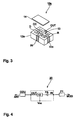
- Fig. 6 shows a perspective view of another high-frequency module of the construction in Fig. 4.
- the high-frequency module 20a is different from the high-frequency module 20 in Fig. 5 in that a metal ground plate 22 is arranged from one side surface of side surfaces facing each other of a laminated body 21a internally containing capacitors C1 through C3 and L1 and L2 (not illustrated) constituting an impedance stabilizing unit 10 to the other side surface through one major surface (a first major surface) and in that a diode D and a high output amplifier PA constituting the impedance stabilizing unit 10 are mounted on the ground plate 22.
Landscapes
- Transmitters (AREA)
- Amplifiers (AREA)
- Microwave Amplifiers (AREA)
- Input Circuits Of Receivers And Coupling Of Receivers And Audio Equipment (AREA)
- Transceivers (AREA)
Applications Claiming Priority (6)
| Application Number | Priority Date | Filing Date | Title |
|---|---|---|---|
| JP324657/97 | 1997-11-26 | ||
| JP32465797 | 1997-11-26 | ||
| JP32465797 | 1997-11-26 | ||
| JP10306934A JPH11312987A (ja) | 1997-11-26 | 1998-10-28 | インピーダンス安定装置及びそれを用いた高周波モジュール |
| JP30693498 | 1998-10-28 | ||
| JP306934/98 | 1998-10-28 |
Publications (2)
| Publication Number | Publication Date |
|---|---|
| EP0920128A2 true EP0920128A2 (de) | 1999-06-02 |
| EP0920128A3 EP0920128A3 (de) | 2002-06-12 |
Family
ID=26564917
Family Applications (1)
| Application Number | Title | Priority Date | Filing Date |
|---|---|---|---|
| EP98122246A Withdrawn EP0920128A3 (de) | 1997-11-26 | 1998-11-23 | Impedanz-Stabilisierungsanlage und Hochfrequenzmodul damit |
Country Status (3)
| Country | Link |
|---|---|
| US (1) | US6069538A (de) |
| EP (1) | EP0920128A3 (de) |
| JP (1) | JPH11312987A (de) |
Cited By (2)
| Publication number | Priority date | Publication date | Assignee | Title |
|---|---|---|---|---|
| WO2001001568A1 (de) * | 1999-06-24 | 2001-01-04 | Infineon Technologies Ag | Schaltungsanordnung zur anpassung eines verstärkers an eine hochfrequenzleitung und verwendung dieser schaltungsanordnung |
| EP1077528A3 (de) * | 1999-08-19 | 2001-03-21 | Murata Manufacturing Co., Ltd. | Filter mit drei Anschlüssen, Empfangsmodul und tragbares Funkgerät |
Families Citing this family (6)
| Publication number | Priority date | Publication date | Assignee | Title |
|---|---|---|---|---|
| JP2003087149A (ja) * | 2001-09-14 | 2003-03-20 | Matsushita Electric Ind Co Ltd | 高周波複合スイッチモジュール |
| JPWO2005083893A1 (ja) * | 2004-03-01 | 2007-08-09 | 三洋電機株式会社 | アイソレーショントラップ回路、アンテナスイッチモジュール、及び送信回路 |
| DE102005037040A1 (de) | 2005-08-05 | 2007-02-08 | Epcos Ag | Elektrisches Bauelement |
| JP5304890B2 (ja) * | 2009-04-01 | 2013-10-02 | 株式会社村田製作所 | アンテナ整合回路、アンテナ装置及びアンテナ装置の設計方法 |
| JP5873466B2 (ja) | 2013-08-23 | 2016-03-01 | 株式会社Nttドコモ | マルチアンテナアレーシステム |
| WO2018101112A1 (ja) * | 2016-11-30 | 2018-06-07 | 株式会社村田製作所 | 配線基板、カプラモジュール、及び通信装置 |
Citations (1)
| Publication number | Priority date | Publication date | Assignee | Title |
|---|---|---|---|---|
| EP0704925A1 (de) | 1994-09-28 | 1996-04-03 | Murata Manufacturing Co., Ltd. | Zusammengestellte Hochfrequenz-Vorrichtung und deren Herstellungsverfahren |
Family Cites Families (8)
| Publication number | Priority date | Publication date | Assignee | Title |
|---|---|---|---|---|
| US4381566A (en) * | 1979-06-14 | 1983-04-26 | Matsushita Electric Industrial Co., Ltd. | Electronic tuning antenna system |
| US4502025A (en) * | 1982-04-23 | 1985-02-26 | Harris Corporation | High speed PIN diode switched antenna coupler and method |
| US4701732A (en) * | 1986-12-16 | 1987-10-20 | Hughes Aircraft Company | Fast tuning RF network inductor |
| DE69221355T2 (de) * | 1991-03-26 | 1998-01-22 | Nippon Sheet Glass Co Ltd | Scheibenantennensystem für Kraftfahrzeug |
| US5564086A (en) * | 1993-11-29 | 1996-10-08 | Motorola, Inc. | Method and apparatus for enhancing an operating characteristic of a radio transmitter |
| JP3186397B2 (ja) * | 1993-12-28 | 2001-07-11 | 株式会社村田製作所 | 高周波スイッチ |
| GB2289989B (en) * | 1994-05-25 | 1999-01-06 | Nokia Mobile Phones Ltd | Adaptive antenna matching |
| JP3650433B2 (ja) * | 1995-07-19 | 2005-05-18 | Tdk株式会社 | アンテナスイッチ |
-
1998
- 1998-10-28 JP JP10306934A patent/JPH11312987A/ja active Pending
- 1998-11-23 EP EP98122246A patent/EP0920128A3/de not_active Withdrawn
- 1998-11-25 US US09/199,834 patent/US6069538A/en not_active Expired - Lifetime
Patent Citations (1)
| Publication number | Priority date | Publication date | Assignee | Title |
|---|---|---|---|---|
| EP0704925A1 (de) | 1994-09-28 | 1996-04-03 | Murata Manufacturing Co., Ltd. | Zusammengestellte Hochfrequenz-Vorrichtung und deren Herstellungsverfahren |
Cited By (3)
| Publication number | Priority date | Publication date | Assignee | Title |
|---|---|---|---|---|
| WO2001001568A1 (de) * | 1999-06-24 | 2001-01-04 | Infineon Technologies Ag | Schaltungsanordnung zur anpassung eines verstärkers an eine hochfrequenzleitung und verwendung dieser schaltungsanordnung |
| US6801757B2 (en) * | 1999-06-24 | 2004-10-05 | Infineon Technologies Ag | Circuit configuration for matching an amplifier to a radio-frequency line, and use of the circuit configuration |
| EP1077528A3 (de) * | 1999-08-19 | 2001-03-21 | Murata Manufacturing Co., Ltd. | Filter mit drei Anschlüssen, Empfangsmodul und tragbares Funkgerät |
Also Published As
| Publication number | Publication date |
|---|---|
| EP0920128A3 (de) | 2002-06-12 |
| US6069538A (en) | 2000-05-30 |
| JPH11312987A (ja) | 1999-11-09 |
Similar Documents
| Publication | Publication Date | Title |
|---|---|---|
| EP1119111B1 (de) | Isolator mit eingebauter leistungsverstärker | |
| US7035602B2 (en) | High-frequency composite switch component | |
| US6937845B2 (en) | High-frequency module and radio device using the same | |
| US6928298B2 (en) | Mobile communication device and high-frequency composite unit used in the same | |
| US6586786B2 (en) | High frequency switch and mobile communication equipment | |
| US6985712B2 (en) | RF device and communication apparatus using the same | |
| US6411176B1 (en) | Voltage-controlled duplexer and communication apparatus | |
| US6522220B2 (en) | Frequency variable filter, antenna duplexer, and communication apparatus incorporating the same | |
| US5392011A (en) | Tunable filter having capacitively coupled tuning elements | |
| US20020017952A1 (en) | Radio freqency signal output module having radio-frequency power amplifier and isolator element | |
| JP3454163B2 (ja) | 周波数可変型フィルタ、アンテナ共用器及び通信機装置 | |
| EP1384281B1 (de) | Antennenschnittstelleneinheit | |
| EP0909023B1 (de) | In einer Vielzahl von Frequenzbändern arbeitendes Filter | |
| US6983129B2 (en) | Radio frequency switch and wireless communication apparatus using the same | |
| US6069538A (en) | Impedance stabilizing unit and high-frequency module using the unit | |
| US6448868B2 (en) | High-frequency switch | |
| GB2382470A (en) | Nonreciprocal circuit device with balanced port | |
| US20040240420A1 (en) | Front end module and high-frequency functional module | |
| US6885261B2 (en) | Dielectric filter, antenna sharing device, and communication device having a voltage controlled reactance element for tuning the center frequency | |
| US20010004353A1 (en) | High frequency composite component and mobile communication apparatus incorporating the same | |
| US6504452B2 (en) | Low-pass filter and mobile communication device using the same | |
| US8193874B2 (en) | High-frequency module | |
| GB2276786A (en) | A voltage controlled filter |
Legal Events
| Date | Code | Title | Description |
|---|---|---|---|
| PUAI | Public reference made under article 153(3) epc to a published international application that has entered the european phase |
Free format text: ORIGINAL CODE: 0009012 |
|
| 17P | Request for examination filed |
Effective date: 19981123 |
|
| AK | Designated contracting states |
Kind code of ref document: A2 Designated state(s): AT BE CH CY DE DK ES FI FR GB GR IE IT LI LU MC NL PT SE |
|
| AX | Request for extension of the european patent |
Free format text: AL;LT;LV;MK;RO;SI |
|
| PUAL | Search report despatched |
Free format text: ORIGINAL CODE: 0009013 |
|
| AK | Designated contracting states |
Kind code of ref document: A3 Designated state(s): AT BE CH CY DE DK ES FI FR GB GR IE IT LI LU MC NL PT SE |
|
| AX | Request for extension of the european patent |
Free format text: AL;LT;LV;MK;RO;SI |
|
| AKX | Designation fees paid |
Designated state(s): DE FI FR GB SE |
|
| RAP1 | Party data changed (applicant data changed or rights of an application transferred) |
Owner name: MURATA MANUFACTURING CO., LTD. |
|
| 17Q | First examination report despatched |
Effective date: 20071002 |
|
| STAA | Information on the status of an ep patent application or granted ep patent |
Free format text: STATUS: THE APPLICATION IS DEEMED TO BE WITHDRAWN |
|
| 18D | Application deemed to be withdrawn |
Effective date: 20110531 |