EP0920041B1 - Schaltereinsatz für Drehschalter - Google Patents
Schaltereinsatz für Drehschalter Download PDFInfo
- Publication number
- EP0920041B1 EP0920041B1 EP98116249A EP98116249A EP0920041B1 EP 0920041 B1 EP0920041 B1 EP 0920041B1 EP 98116249 A EP98116249 A EP 98116249A EP 98116249 A EP98116249 A EP 98116249A EP 0920041 B1 EP0920041 B1 EP 0920041B1
- Authority
- EP
- European Patent Office
- Prior art keywords
- switch
- wiper
- contacts
- insert
- segments
- Prior art date
- Legal status (The legal status is an assumption and is not a legal conclusion. Google has not performed a legal analysis and makes no representation as to the accuracy of the status listed.)
- Expired - Lifetime
Links
- 239000004020 conductor Substances 0.000 claims description 3
- 238000010438 heat treatment Methods 0.000 claims description 3
- 238000004378 air conditioning Methods 0.000 claims description 2
- 230000011664 signaling Effects 0.000 claims description 2
- 238000009423 ventilation Methods 0.000 claims description 2
- 238000013459 approach Methods 0.000 description 1
- 238000010276 construction Methods 0.000 description 1
- 238000011161 development Methods 0.000 description 1
- 230000018109 developmental process Effects 0.000 description 1
Images


Classifications
-
- H—ELECTRICITY
- H01—ELECTRIC ELEMENTS
- H01H—ELECTRIC SWITCHES; RELAYS; SELECTORS; EMERGENCY PROTECTIVE DEVICES
- H01H19/00—Switches operated by an operating part which is rotatable about a longitudinal axis thereof and which is acted upon directly by a solid body external to the switch, e.g. by a hand
- H01H19/54—Switches operated by an operating part which is rotatable about a longitudinal axis thereof and which is acted upon directly by a solid body external to the switch, e.g. by a hand the operating part having at least five or an unspecified number of operative positions
- H01H19/56—Angularly-movable actuating part carrying contacts, e.g. drum switch
- H01H19/58—Angularly-movable actuating part carrying contacts, e.g. drum switch having only axial contact pressure, e.g. disc switch, wafer switch
-
- H—ELECTRICITY
- H01—ELECTRIC ELEMENTS
- H01H—ELECTRIC SWITCHES; RELAYS; SELECTORS; EMERGENCY PROTECTIVE DEVICES
- H01H1/00—Contacts
- H01H1/12—Contacts characterised by the manner in which co-operating contacts engage
- H01H1/36—Contacts characterised by the manner in which co-operating contacts engage by sliding
- H01H1/365—Bridging contacts
Definitions
- the invention relates to a switch insert for rotary switch according to the preamble of Patent claim 1.
- Such a switch insert is disclosed for example in DE 28 24 584 A1 and There already has a contact plate with Schleifersegmenten and connector leads for power supply and wiring and a switch grinder on the rotary switch can be adjusted. Overall, however, results for this construction a relatively high height, the use of this rotary switch, for example in vehicle uprights, does not allow.
- this switch is not suitable for today's requirements, i. higher Current loads that can occur when switching on and off blower motors, Window heating etc.
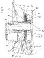
- Fig. 1 shows a section through an operating element 1 for heating, air conditioning and / or ventilation systems of motor vehicles from which the arrangement of a switch insert 2 and a rotary switch 3 can be removed.
- the switch insert 2 consists of a contact plate 4 with Schleifersegmenten 5 and Plug connection conductors 6 for energizing and wiring and a switch grinder 7, which can be adjusted by the rotary switch 3.
- Schleifersegmente 5 within a plastic plate 8 so arranged are that they contacted from the other side by another switch grinder 9 can be, whose contacts 10 mirror images of the contacts 11 of the first Switch grinder 7 are arranged, wherein the further switch grinder 9 guide lugs 12, which by guide recesses 13 of the first switch grinder. 7 protrude and record in a retaining slot 14, a leaf spring 15, on the other hand under resilient tension on the contacts 11 facing away from the surface first switch grinder 7 is supported and thereby the contacts 10, 11 both switch grinder 7, 9 loaded against the grinder segments 5.
- the switch insert 2 is arranged on a bearing journal 16, which at the same time the rotary switch 3 stores, which with a driver lug 17 in a guide recess 18 of the Switch insert 2 protrudes and the switch grinder 7, 9 carries.
- the leaf spring 15th has two resilient latching arms 19 which cooperate with latching steps 20 of the journal 16 and the locking of the contacts 10, 11 of the switch grinder 7, 9 with respect to cause the Schleifersegmente 5.
- Fig. 2 shows the switch insert 2 as a single part with the contact plate 4, as a plastic plate 8 is executed, in which the grinder segments 5 against each other electrically isolated are embedded.
- the wiper segments 5 are connected to the plug connection conductors 6.
- Fig. 3 shows in exploded view the items plastic plate 8, the two switch grinder 7.9 and the leaf spring 15.
- the switch grinder 9 shows the management approaches 12 with the retaining slots 14 for the leaf spring 15th
- Switch grinder 7 shows the guide recesses 13, with the guide lugs 12th of the switch grinder 9-cooperate.
- Leaf spring 15 shows Auflageabbiegonne 21, facing away from the contacts 11 Surface of the Wegerschleiffers 7 come to rest and the contacts 10, 11 against the Load grinder segments 5.
- the latching arms 19 are by bent projections of the leaf spring 15 formed.
- one of the slider segments 5 as a zero position signaling contact 22 is executed, so that the zero position, for example, an electronic control unit or a security circuit can be identified.
Landscapes
- Rotary Switch, Piano Key Switch, And Lever Switch (AREA)
Description
einen Schnitt durch einen Drehschalter;
eine perspektivische Ansicht eines Schaltereinsatzes als Einzelteil;
eine Explosionsdarstellung des Schaltereinsatzes nach Fig. 2.
Claims (4)
- Schaltereinsatz (2) für Drehschalter (3), insbesondere von Bedienelementen (1) für Heizungs-, Klima- und/oder Lüftungsanlagen von Kraftfahrzeugen, bestehend aus einer Kontaktplatte (4) mit Schleifersegmenten (5) und Steckeranschlußleitern (6) für Bestromung und Beschaltung und aus einem ersten Schalterschleifer (7), der von dem Drehschalter (3) verstellt werden kann, wobei die Schleifersegmente (5) innerhalb einer Kunststoffplatte (8) so angeordnet sind, daß sie von der anderen Seite durch einen weiteren Schalterschleifer (9) kontaktiert werden, dessen Kontakte spiegelbildlich zu den Kontakten des ersten Schalterschleifers (7) angeordnet sind, dadurch gekennzeichnet, daß der weitere Schalterschleifer (9) Führungsansätze (12) aufweist, die durch Führungsausnehmungen (13) des ersten Schalterschleifers (7) hindurchragen und in einem Halteschlitz (14) eine Blattfeder (15) aufnehmen, die sich andererseits unter federnder Verspannung auf der den Kontakten (11) abgewandten Fläche des ersten Schalterschleifers (7) abstützt und dadurch die Kontakte (10, 11) beider Schalterschleifer (7, 9) gegen die Schleifersegmente (5) belastet.
- Schaltereinsatz nach Anspruch 1, dadurch gekennzeichnet, daß der Schaltereinsatz (2) auf einem Lagerzapfen (16) angeordnet ist, der gleichzeitig den Drehschalter (3) lagert, der mit einem Mitnehmeransatz (17) in eine Führungsausnehmung (18) des Schaltereinsatzes (2) hineinragt.
- Schaltereinsatz nach Anspruch 2, dadurch gekennzeichnet, daß die Blattfeder (15) zwei federnde Rastarme (19) aufweist, die mit Raststufen (20) des Lagerzapfens (16) zusammenwirken.
- Schaltereinsatz nach einem der vorstehenden Ansprüche, dadurch gekennzeichnet, daß einer der Schleifersegmente (5) als Nullstellungsmeldekontakt (22) ausgeführt ist.
Applications Claiming Priority (2)
| Application Number | Priority Date | Filing Date | Title |
|---|---|---|---|
| DE19753079A DE19753079C1 (de) | 1997-11-29 | 1997-11-29 | Schaltereinsatz für Drehschalter |
| DE19753079 | 1997-11-29 |
Publications (3)
| Publication Number | Publication Date |
|---|---|
| EP0920041A2 EP0920041A2 (de) | 1999-06-02 |
| EP0920041A3 EP0920041A3 (de) | 2000-05-10 |
| EP0920041B1 true EP0920041B1 (de) | 2005-04-20 |
Family
ID=7850279
Family Applications (1)
| Application Number | Title | Priority Date | Filing Date |
|---|---|---|---|
| EP98116249A Expired - Lifetime EP0920041B1 (de) | 1997-11-29 | 1998-08-28 | Schaltereinsatz für Drehschalter |
Country Status (3)
| Country | Link |
|---|---|
| US (1) | US6066813A (de) |
| EP (1) | EP0920041B1 (de) |
| DE (2) | DE19753079C1 (de) |
Family Cites Families (14)
| Publication number | Priority date | Publication date | Assignee | Title |
|---|---|---|---|---|
| DE489822C (de) * | 1930-01-22 | Voigt & Haeffner Akt Ges | Anordnung fuer die Erhoehung der Abschaltleistung von Drehschaltern | |
| US3478180A (en) * | 1968-05-14 | 1969-11-11 | Stockpole Carbon Co | Rotary electric switch |
| US3501598A (en) * | 1968-08-20 | 1970-03-17 | Kollsman Instr Corp | Electric switch assembly for printed circuit installations |
| US3780238A (en) * | 1971-12-27 | 1973-12-18 | Beckman Instruments Inc | Multi sectional rotary wafer switch assembly with improved support and terminal connector for thin circuit module |
| US3924185A (en) * | 1973-08-30 | 1975-12-02 | Rite Autotronics Corp | Electrical meter construction |
| US4166200A (en) * | 1975-08-11 | 1979-08-28 | Tektronix, Inc. | Compact rotary switch construction |
| US4038504A (en) * | 1975-11-19 | 1977-07-26 | A.C. Nielsen Company | Rotary, printed circuit wafer switch and method for adjusting |
| DE2824584C2 (de) * | 1978-06-05 | 1986-02-06 | Ebe Elektro-Bau-Elemente Gmbh, 7022 Leinfelden-Echterdingen | Mehrfach-Stufendrehschalter |
| GB2043347B (en) * | 1979-02-28 | 1983-02-02 | Bun Wong | Electrical switch |
| JPS59125806U (ja) * | 1983-02-12 | 1984-08-24 | アルプス電気株式会社 | 2軸型回転電気部品 |
| US4510360A (en) * | 1983-06-08 | 1985-04-09 | Westinghouse Electric Corp. | Circuit breaker with arc shield |
| US4723059A (en) * | 1986-10-16 | 1988-02-02 | Teleflex Incorporated | Tachometer switch |
| US5290980A (en) * | 1992-07-08 | 1994-03-01 | Indak Manufacturing Corp. | Rotary vacuum-electric switch |
| US5315077A (en) * | 1993-04-05 | 1994-05-24 | Bourns, Inc. | Rotary switch including cam operated flexible contacts |
-
1997
- 1997-11-29 DE DE19753079A patent/DE19753079C1/de not_active Expired - Fee Related
-
1998
- 1998-08-28 DE DE59812743T patent/DE59812743D1/de not_active Expired - Lifetime
- 1998-08-28 EP EP98116249A patent/EP0920041B1/de not_active Expired - Lifetime
- 1998-11-09 US US09/188,197 patent/US6066813A/en not_active Expired - Fee Related
Also Published As
| Publication number | Publication date |
|---|---|
| US6066813A (en) | 2000-05-23 |
| EP0920041A3 (de) | 2000-05-10 |
| DE59812743D1 (de) | 2005-05-25 |
| DE19753079C1 (de) | 1998-10-29 |
| EP0920041A2 (de) | 1999-06-02 |
Similar Documents
| Publication | Publication Date | Title |
|---|---|---|
| DE69734095T2 (de) | Energieverteilungseinheit | |
| EP0350504B1 (de) | Ventilblockaggregat | |
| DE69705000T2 (de) | Kabelbaumstruktur in Kraftfahrzeugen | |
| DE3630816A1 (de) | Funktionsschaltung mit einer eingebauten typenverdrahtungsvorrichtung fuer kraftfahrzeuge | |
| DE3439410A1 (de) | Einrichtung fuer ein kraftfahrzeug | |
| DE69505450T2 (de) | Stecker | |
| EP0846351B1 (de) | Anordnung mit zwei steckerhälften zur fixierung in einer wandung | |
| EP1261507A1 (de) | Lenkrad für kraftfahrzeuge mit einer schalteinrichtung zum betätigen einer elektrischen funktionsgruppe eines kraftfahrzeugs | |
| DE2844346A1 (de) | Verbinder zum verbinden einer kraftfahrzeugscheinwerfer-lampe mit einer gedruckten schaltungsplatte | |
| EP1665480B1 (de) | Vorrichtung zum herstellen einer elektrischen verbindung | |
| DE3333138A1 (de) | Schalterleiste an einem armaturenbrett fuer fahrzeuge, insbesondere kraftfahrzeuge | |
| DE8421441U1 (de) | Als Diebstahlssicherung dienende Vorrichtung für ein elektrisches Empfangs- und/oder Wiedergabegerät | |
| DE19753079C1 (de) | Schaltereinsatz für Drehschalter | |
| DE19612063C2 (de) | Elektrisches Steuergerät für Fahrzeuge | |
| DE8711687U1 (de) | Bedienteil für ein Autoradio | |
| DE2627918C3 (de) | Schaltungsanordnung für elektrische Verbraucher in einem Kraftfahrzeug | |
| DE4015619C2 (de) | ||
| DE4329994C2 (de) | Elektrisches Steckverbindersystem | |
| EP0341416B1 (de) | Schalteinrichtung | |
| EP0873254A1 (de) | Überschaltsicherung für lenkstockschalter mit automatischer rückstellung | |
| EP0920081B1 (de) | Drehschalter oder -widerstand | |
| EP0715382A1 (de) | Vorrichtung zur Befestigung eines Gehäuses | |
| DE19707170A1 (de) | Stufenschalter | |
| DE102021206605B4 (de) | Verbindungselement für ein Versorgungskabel zum elektrischen Verbinden eines Fahrzeugs mit einer Energieversorgungseinrichtung | |
| DE69704012T2 (de) | Kraftfahrzeugdiebstahlsicherung mit zusammenarbeitendem Zündschloss |
Legal Events
| Date | Code | Title | Description |
|---|---|---|---|
| PUAI | Public reference made under article 153(3) epc to a published international application that has entered the european phase |
Free format text: ORIGINAL CODE: 0009012 |
|
| AK | Designated contracting states |
Kind code of ref document: A2 Designated state(s): DE FR GB IT |
|
| AX | Request for extension of the european patent |
Free format text: AL;LT;LV;MK;RO;SI |
|
| PUAL | Search report despatched |
Free format text: ORIGINAL CODE: 0009013 |
|
| AK | Designated contracting states |
Kind code of ref document: A3 Designated state(s): AT BE CH CY DE DK ES FI FR GB GR IE IT LI LU MC NL PT SE |
|
| AX | Request for extension of the european patent |
Free format text: AL;LT;LV;MK;RO;SI |
|
| RIC1 | Information provided on ipc code assigned before grant |
Free format text: 7H 01H 19/10 A, 7H 01H 19/58 B, 7H 01H 1/36 B |
|
| 17P | Request for examination filed |
Effective date: 20000405 |
|
| AKX | Designation fees paid |
Free format text: DE FR GB IT |
|
| RAP1 | Party data changed (applicant data changed or rights of an application transferred) |
Owner name: PREH GMBH |
|
| GRAP | Despatch of communication of intention to grant a patent |
Free format text: ORIGINAL CODE: EPIDOSNIGR1 |
|
| GRAS | Grant fee paid |
Free format text: ORIGINAL CODE: EPIDOSNIGR3 |
|
| GRAA | (expected) grant |
Free format text: ORIGINAL CODE: 0009210 |
|
| AK | Designated contracting states |
Kind code of ref document: B1 Designated state(s): DE FR GB IT |
|
| PG25 | Lapsed in a contracting state [announced via postgrant information from national office to epo] |
Ref country code: IT Free format text: LAPSE BECAUSE OF FAILURE TO SUBMIT A TRANSLATION OF THE DESCRIPTION OR TO PAY THE FEE WITHIN THE PRESCRIBED TIME-LIMIT;WARNING: LAPSES OF ITALIAN PATENTS WITH EFFECTIVE DATE BEFORE 2007 MAY HAVE OCCURRED AT ANY TIME BEFORE 2007. THE CORRECT EFFECTIVE DATE MAY BE DIFFERENT FROM THE ONE RECORDED. Effective date: 20050420 Ref country code: GB Free format text: LAPSE BECAUSE OF FAILURE TO SUBMIT A TRANSLATION OF THE DESCRIPTION OR TO PAY THE FEE WITHIN THE PRESCRIBED TIME-LIMIT Effective date: 20050420 |
|
| REG | Reference to a national code |
Ref country code: GB Ref legal event code: FG4D Free format text: NOT ENGLISH |
|
| REF | Corresponds to: |
Ref document number: 59812743 Country of ref document: DE Date of ref document: 20050525 Kind code of ref document: P |
|
| GBV | Gb: ep patent (uk) treated as always having been void in accordance with gb section 77(7)/1977 [no translation filed] |
Effective date: 20050420 |
|
| PLBE | No opposition filed within time limit |
Free format text: ORIGINAL CODE: 0009261 |
|
| STAA | Information on the status of an ep patent application or granted ep patent |
Free format text: STATUS: NO OPPOSITION FILED WITHIN TIME LIMIT |
|
| 26N | No opposition filed |
Effective date: 20060123 |
|
| EN | Fr: translation not filed | ||
| PG25 | Lapsed in a contracting state [announced via postgrant information from national office to epo] |
Ref country code: FR Free format text: LAPSE BECAUSE OF NON-PAYMENT OF DUE FEES Effective date: 20050831 |
|
| PG25 | Lapsed in a contracting state [announced via postgrant information from national office to epo] |
Ref country code: FR Free format text: LAPSE BECAUSE OF NON-PAYMENT OF DUE FEES Effective date: 20050420 |
|
| PGFP | Annual fee paid to national office [announced via postgrant information from national office to epo] |
Ref country code: DE Payment date: 20090821 Year of fee payment: 12 |
|
| REG | Reference to a national code |
Ref country code: DE Ref legal event code: R119 Ref document number: 59812743 Country of ref document: DE Effective date: 20110301 |
|
| PG25 | Lapsed in a contracting state [announced via postgrant information from national office to epo] |
Ref country code: DE Free format text: LAPSE BECAUSE OF NON-PAYMENT OF DUE FEES Effective date: 20110301 |