EP0919971B1 - Diebstahl-Sicherungssystem sowie Verfahren zur automatischen Detektion und Identifikation eines Warensicherungsetiketts durch eine Basisstation - Google Patents
Diebstahl-Sicherungssystem sowie Verfahren zur automatischen Detektion und Identifikation eines Warensicherungsetiketts durch eine Basisstation Download PDFInfo
- Publication number
- EP0919971B1 EP0919971B1 EP98118521A EP98118521A EP0919971B1 EP 0919971 B1 EP0919971 B1 EP 0919971B1 EP 98118521 A EP98118521 A EP 98118521A EP 98118521 A EP98118521 A EP 98118521A EP 0919971 B1 EP0919971 B1 EP 0919971B1
- Authority
- EP
- European Patent Office
- Prior art keywords
- base station
- transponder
- signal
- stage
- alarm
- Prior art date
- Legal status (The legal status is an assumption and is not a legal conclusion. Google has not performed a legal analysis and makes no representation as to the accuracy of the status listed.)
- Expired - Lifetime
Links
Images

Classifications
-
- G—PHYSICS
- G08—SIGNALLING
- G08B—SIGNALLING SYSTEMS, e.g. PERSONAL CALLING SYSTEMS; ORDER TELEGRAPHS; ALARM SYSTEMS
- G08B13/00—Burglar, theft or intruder alarms
- G08B13/22—Electrical actuation
- G08B13/24—Electrical actuation by interference with electromagnetic field distribution
- G08B13/2402—Electronic Article Surveillance [EAS], i.e. systems using tags for detecting removal of a tagged item from a secure area, e.g. tags for detecting shoplifting
- G08B13/2465—Aspects related to the EAS system, e.g. system components other than tags
- G08B13/2482—EAS methods, e.g. description of flow chart of the detection procedure
-
- G—PHYSICS
- G06—COMPUTING OR CALCULATING; COUNTING
- G06K—GRAPHICAL DATA READING; PRESENTATION OF DATA; RECORD CARRIERS; HANDLING RECORD CARRIERS
- G06K19/00—Record carriers for use with machines and with at least a part designed to carry digital markings
- G06K19/06—Record carriers for use with machines and with at least a part designed to carry digital markings characterised by the kind of the digital marking, e.g. shape, nature, code
- G06K19/067—Record carriers with conductive marks, printed circuits or semiconductor circuit elements, e.g. credit or identity cards also with resonating or responding marks without active components
- G06K19/07—Record carriers with conductive marks, printed circuits or semiconductor circuit elements, e.g. credit or identity cards also with resonating or responding marks without active components with integrated circuit chips
- G06K19/0723—Record carriers with conductive marks, printed circuits or semiconductor circuit elements, e.g. credit or identity cards also with resonating or responding marks without active components with integrated circuit chips the record carrier comprising an arrangement for non-contact communication, e.g. wireless communication circuits on transponder cards, non-contact smart cards or RFIDs
-
- G—PHYSICS
- G08—SIGNALLING
- G08B—SIGNALLING SYSTEMS, e.g. PERSONAL CALLING SYSTEMS; ORDER TELEGRAPHS; ALARM SYSTEMS
- G08B13/00—Burglar, theft or intruder alarms
- G08B13/22—Electrical actuation
- G08B13/24—Electrical actuation by interference with electromagnetic field distribution
- G08B13/2402—Electronic Article Surveillance [EAS], i.e. systems using tags for detecting removal of a tagged item from a secure area, e.g. tags for detecting shoplifting
- G08B13/2465—Aspects related to the EAS system, e.g. system components other than tags
- G08B13/2468—Antenna in system and the related signal processing
- G08B13/2471—Antenna signal processing by receiver or emitter
Definitions
- the invention relates to the field of anti-theft systems for goods.
- the invention relates to an anti-theft system to secure goods comprising a base station that generates an electromagnetic field emitted by an antenna, and one or more cooperating with the base station, one each Response security-generating goods security labels, with each goods such a security label is attached and being before leaving of the goods-secured place the goods by the electromagnetic Field of the base station must be kept at which Carrying out a security label that can be detected by the base station Response signal is generated.
- the invention further relates to a method for automatic detection and identification of a security tag by a base station.
- Theft protection systems of this type are used, for example, in department stores used to counter in particular higher-priced goods Protect theft better.
- a base station through which the Covering the area of the output generates an electromagnetic field becomes.
- Security tags are attached to the goods to be protected. When lawfully paying for such goods, is usually either removed the security tag at the checkout or destroyed. If a person with the paid goods passes through on Electromagnetic field exit of the department store, responds the base station is not. On the other hand, would like a person with a product an existing or still functional security label pass through the electromagnetic field of the base station, then such a security tag is detected by the base station, whereupon an alarm is triggered.
- Security labels are known which are detectable for the base station Response signal of an electromagnetic type, for example by energy absorption produce.
- an anti-theft system is for example described in EP 0 663 657 A1.
- An energy absorptive working system uses one from coil and in the security label Capacitor formed resonant circuit. Through this resonant circuit a second when entering the electromagnetic field of the base station generates an alternating magnetic field, which is transmitted via an antenna from the base station can be detected.
- Such systems usually work in the HF range at 1 to 2 MHz.
- System can also be outwitted by putting the security label in front passing through the electromagnetic generated by the base station Field is shielded from this.
- a shield can already be achieved in that such a security label or the entire goods with the security label in aluminum foil or other metallic foils is wrapped.
- Such a system could be outwitted by the fact that Goods protected with such security labels in an aluminum case transported through the electromagnetic field of the base station to be brought. Because the electromagnetic generated by the base station Field is not affected and thus the base station has no response signal accordingly, no alarm is triggered.
- a problem in these known systems is also in of several such security tags in the detection field of the base station enter one after the other.
- the first security label then blocks the base station in alarm.
- security tags entering the base station then pass the base station unnoticed.
- One in the area of such The base station's hidden security label can cover the entire Put the system out of operation permanently.
- the invention lies on the basis of this prior art discussed hence the task of proposing an anti-theft system, which is less sensitive to manipulation.
- the invention is also based on the object of a Manipulation possibility improved method for automatic Detection and identification of one or more security tags to be provided by a base station.
- the system-related object is achieved in that the base station has a low-frequency LF stage with an LF transceiver and that those interacting with the base station Security tags each have an active transponder with an LF stage operating on the same frequency with an LF transceiver unit include, so that a bidirectional signal transmission is feasible between the base station and a transponder.
- both the base station and the security tag are in the low frequency range working NF stage with one NF transmitter / receiver unit each is assigned, with data transmission in the frequency domain between 5 and 100 KHz is appropriate, a system is set up, its signal transmission based on the selected frequency is not easily shielded. It is intended that the electromagnetic field generated at the base station NF stage is a cyclical one in which a control signal is sent.
- the security label an NF level with an NF transmitter / receiver unit has an active security tag designed as a transponder created so that between the base station and such security tag designed as a transponder a bidirectional Signal transmission (data transmission) is possible. With such a bidirectional Signal transmission can have multiple authorization checks or validity checks are carried out so that an alarm is triggered can be coupled to different verification steps. It also significantly reduces false alarms.
- the NF stage sends the base station for the purpose of further checking after receiving a response signal sent by the transponder an acknowledgment signal.
- This acknowledgment signal can either be encoded as an enable signal, which indicates the successful Acknowledgment of completion of the bidirectional data transmission.
- On the system side is such a transponder (with the goods attached to it) authorized to leave the secured place of goods.
- a non-enable signal can also be sent, which Non-release signal either as part of an anti-collision monitoring by the base station an assignment of those receiving the response signals Represents the base station or the transponder to a new one
- the response signal is emitted or another control command is issued can be.
- the for Sending the response signal of the transponder provided transmitters can be, for example, the NF transmitter of the NF stage.
- such System not only to be used as an anti-theft system, but the response signal sent by the transponder can be additional Contain information about the goods identity, for example that these response signals received by the base station correspond to a corresponding one Goods management can be fed.
- the one sent by the base station Acknowledgment of receipt signal is sent on the NF route, especially to overcome manipulative shields. Since the The base station is expediently not battery-operated but powered by an electrical network works, is the transmission power of the NF level of the base station many times higher than the transmission power of the NF level of the transponder. Therefore, an acknowledgment signal sent on the NF line can also to penetrate possible shields. Is a shielded such security tag with respect to the RF link, sends the NF level of the base station, since there is no response signal from the RF receiver the transponder has been received, also no acknowledgment signal out.
- the NF transmitter unit of the NF stage of the transponder used to send an alarm signal on the NF line.
- This alarm signal is received by the base station, whereupon a Alarm is triggered.
- An acoustic signal from the base station can be used as an alarm and / or visual alarm, such as a siren, can be actuated.
- it can also send out an alarm signal on the NF line instead of the other or in addition to the other alarm mechanisms be sent, which alarm signal is a control command contains, which puts the transponder into an alarm mode.
- the the alarm triggered by the transponder can also be visual or acoustic Be natural so that the transponder set in alarm mode by the security personnel is detectable.
- the RF level of the transponder is at an antenna detuning device connected with the help of the detection of one Antenna detuning, for example by shielding an antenna detuning is brought about. It is provided that normally Detune air-tuned antenna on metal.
- a bidirectional dialog is carried out, both the transponder and the base station, each with an RF stage, comprising an RF transceiver equip.
- RF stage comprising an RF transceiver equip.
- the base station can receive an alarm signal receiver be assigned, whose reception area essentially is arranged outside the effective range of the base station. Should that Route on which a response signal is received by the base station should be occupied, and the transponder on the NF route have received a corresponding interference signal which the transponder in an alarm position switches and the transponder then an alarm signal transmits, this can be from the undisturbed alarm signal receiver be received. After receiving this signal, the Alarm signal receiver then a system alarm corresponding to one of system alarm triggered by the base station.
- the anti-theft system it is particularly advantageous to add the anti-theft system to operate with an anti-collision method, so that a variety of Transponders regulated by the base station detected and identified and can communicate with them.
- an anti-collision method for example, is it possible that a person with a a person-specific personal transponder is equipped and together with various with corresponding security labels equipped objects enters the effective range of the base station and all transponders are detected and identified during the stay can be.
- the base station can then assign a person and authorization check and a corresponding assignment and authorization check of the carried object be performed.
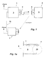
- An anti-theft security system for securing goods includes one Base station 1 and a variety of transponders, of which in figure 1 a transponder 2 is shown.
- the transponder 2 is in a security tag included, which is attached to a product to be secured is.
- the base station 1 is in the area of an exit of a goods-secured Place, such as a department store installed in such a way that the goods leaving this place, on which such a security label is attached, passed through the effective range of the base station 1 Need to become.
- the base station 1 has an NF stage 3, which consists of a transmitter unit as well a receiving unit.
- An antenna 4 is assigned to NF level 3, by means of the signals to be sent on the NF line and with which data to be received on the NF link are received can.
- the transponder 2 also includes an NF level 5, which consists of a transmitter unit and a receiver unit, which transmitter-receiver unit commonly used the NF antenna 6.
- Both modules - base station 1 and transponder 2 - also each include a processor unit, which processor units additional actuators, about an alarm system.
- a schematic diagram shows the arrangement of an anti-theft system in FIG. 1a consisting of base station 1 and an additional one Alarm signal receiver 7 shown.
- the anti-theft system is in the area of exit 8 of a department store, not shown arranged.
- the effective area 9 of the base station 1 is outlined with a short dash and represents the area in which a transponder 2 is set can receive wake-up signal sent by base station 1.
- the alarm receiver 7 is arranged outside the effective range 9, whose reception area 10 is shown in long dash lines.
- the Alarm signal receiver 7 is located, for example, at the output of a Windscreen that 8 people using this exit pass through have to.
- the base station 1 and the alarm signal receiver 7 are through a synchronization line SL connected with each other. Through this synchronization line SL there is a synchronization between the transmission mode the base station 1 and the receiving operation of the alarm signal receiver 7.
- the synchronization is designed so that the cyclical LF signal 3 of base station 1 sending the wake-up signal means that it is ready to receive of the alarm signal receiver 7 controls cyclically.
- the alarm signal receiver 7 can then a broadcast on the NF route Alarm signal received if NF level 3 does not send a wake-up signal. There is thus mutual interference between the base station 1 and the alarm signal receiver 7 avoided.
- that for the duration of the transmission of the control or wake-up signal of the base station 1 of the alarm signal receiver 7 muted via attenuators so that the alarm signal receiver 7 is influenced is avoided by sending the wake-up signal of NF level 3.
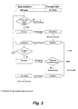
- the base station 1 checks whether the Reception channel on the NF line is busy. Is this due to a jammer manipulated and thus occupied, the base station 1 becomes a system alarm triggered. If the base station 1 works with an anti-collision algorithm, is from NF level 3 when the reception channel is occupied by communication with another transponder 2 a waiting signal Posted. If the receiving channel is free, NF level 3 transmits on NF route a wake-up signal, which when using an anti-collision method is encoded. This wake-up signal is transmitted from one to the Area of effect of the base station 1 located transponder 2 with its NF level 5 received.
- the received wake-up signal leads to a Wake up the NF transmitter 5 so that it is only in operation when the transponder 2 is actually in the effective range of the base station 1 is located and thus also response signals sent by the NF transmitter 3 are receivable from the base station 1.
- That from base station 1 received NF response signal contains an identification code. In the this code is received by the processor unit assigned to base station 1 and checked for validity.
- the transponder data is uniquely decoded and the transponder is thus identified an acknowledgment signal is sent from base station 1 to transponder 2.
- the acknowledgment signal represents, as it were, an acknowledgment signal with which the Transponder 2 receives the message that its response signal has been received, properly decoded and a transponder identification took place Has.
- the transponder 2 Since the communication between the base station and the transponder 2 can sometimes be temporarily disturbed, the transponder 2 repeats Reception of the alarm signal corresponding to a predetermined number (n times) his response signal. It is provided that the number of repetition of the response signal is adjustable. If after the repetition of the answer signal repetition no acknowledgment signal from the transponder 2 has been received, the transponder sends at (n + 1) .mal for the last time a response signal. He also receives this response signal no acknowledgment signal from base station 1, the transponder 2 switches over to malfunction. In this case, sends the transponder has a special alarm signal. This alarm signal can be designed, for example, as a continuous signal. Instead of or together with the transmission of an alarm signal, the transponder 2 itself also generate an optical or acoustic alarm.
- the alarm signal sent by the transponder 2 can be used in the event that the NF receiver 3 or the alarm signal receiver of the base station 1 is manipulatively blocked by a jammer, not received become. For this purpose it lends itself outside the sphere of activity the base station 1 to another alarm signal receiver 7 position, from which the alarm signal of transponder 2 is then received and which then triggers a system alarm.
- This Security is increased by the fact that in bidirectional communication between the base station 1 and the transponder 2 checking mechanisms are provided and that certain non-compliance Criteria an alarm is triggered.
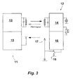
- FIG 3 is another base station 11 and another transponder 12, each of which includes an NF stage 13, 14, each an LF transceiver unit also have an RF stage 15, 16. It is provided that the RF stage 16 of the transponder 12 as The transmitter and the RF stage 15 of the base station 11 are designed as receivers is.
- the antenna 17 assigned to the HF stage 16 is connected to a detuning circuit 18 connected with which the antenna 17 with respect to its Match can be detuned.
- the anti-theft system shown in Figure 3 is particularly useful when the data transmitted in the response signal are so extensive that a Data transmission on the NF line takes too much time would. Especially when using an anti-collision method the provision of an RF stage 15, 16 is therefore appropriate.
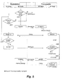
- this transponder 12 In addition to the operating sequence shown in FIG. 2, this takes place in this Anti-theft system, as shown in Figure 4, in addition to Checking the occupancy of the NF reception channel including an occupancy check of the RF reception channel of the RF stage 15 of the base station 11. In the event that after waking up through NF level 14 of Transponders 12 multiple, i.e. (n + 1) times unsuccessful and therefore without receipt an acknowledgment signal, the response signal on the RF link has been sent, this transponder 12 also takes place Switchover to a fault or alarm mode. This sturgeon or Alarm operation can be according to the embodiment shown in Figure 1 be trained.
- the response signal sent by the RF stage 16 not received this may be because the security tag, i.e. the transponder 12 has been manipulated by shielding is.
- the antenna 17 is then detuned on the basis of the Detuning circuit 18, whereby the influence on the RF antenna 17 through the outer shield largely cleared, at least however is minimized.
- the transponder can also do this by receiving a corresponding control signal on the NF line switched from the base station 11 to the toggle operation described above become.
- FIG. 1 The operation of a further anti-theft security system is schematized in FIG shown, in which both the base station and the Transponder in addition to a complete NF level, a complete HF level have as a transceiver.
- the system can then have a bidirectional dialogue on the HF link the base station and the transponder take place.
- Such Design is particularly useful if between the two Modules an increased data exchange should take place; e.g. around against eavesdropping to carry out an authentication of the radio link or to replace those Protect data with passwords or encrypt it too to ship.
- With bidirectional data traffic on the HF route it is far safer, possible manipulations triggered by shielding or to be recognized by third-party or jamming stations.
- a bidirectional LF section is also optionally available the base station the alarm mode can be initiated in the transponder.
- the transmission power of the base station on the NF section is much stronger and thus also NF-related shielding attempts penetrated and thus received by the transponder can.
Landscapes
- Engineering & Computer Science (AREA)
- Physics & Mathematics (AREA)
- General Physics & Mathematics (AREA)
- Signal Processing (AREA)
- Automation & Control Theory (AREA)
- Computer Security & Cryptography (AREA)
- Electromagnetism (AREA)
- Computer Networks & Wireless Communication (AREA)
- Computer Hardware Design (AREA)
- Microelectronics & Electronic Packaging (AREA)
- Theoretical Computer Science (AREA)
- Burglar Alarm Systems (AREA)
Description
- Senden eines niederfrequenten Kontrollsignales durch die NF-Stufe der Basisstation,
- Empfangen des Kontrollsignales durch die NF-Stufe des Transponders,
- Senden eines Antwortsignales durch einen dem Transponder zugeordneten Sender,
- Empfangen des Antwortsignales durch eine auf gleicher Frequenz arbeitende Empfangseinheit der Basisstation,
- Senden eines Empfangsbestätigungssignales durch die Basisstation und
- Empfangen des Empfangsbestätigungssignales durch den Transponder,
- wobei bei Empfang eines Nichtfreigabesignales durch den Transponder oder bei Nichtempfang eines Empfangsbestätigungssignales nach wiederholtem Senden des Antwortsignales der Transponder auf der NF-Strecke einen Alarm auslöst und
- wobei vor und/oder während der Signalübermittlung durch die Basisstation eine Belegungsüberprüfung hinsichtlich einer Fremdbelegung der zum Empfang des Antwortsignals verwendeten Strecke erfolgt und bei der Feststellung einer Fremdbelegung eine Belegungsmeldung ausgegeben wird.
- Fig. 1:
- ein schematisiertes Blockschaltbild eines Diebstahl-Sicherungssystems zur Sicherung von Waren,
- Fig. 1a:
- die Anordnung des Diebstahl-Sicherungssystems der Figur 1 in einer schematisierten Draufsicht,
- Fig. 2:
- ein schematisiertes Flußdiagramm zum Detektieren und Identifizieren eines Warensicherungsetikettes durch eine Basisstation mit dem in Figur 1 gezeigten Diebstahl-Sicherungssystem,
- Fig. 3:
- ein schematisiertes Blockschaltbild eines weiteren Diebstahl-Sicherungssystems zur Sicherung von Waren,
- Fig. 4:
- ein schematisiertes Flußdiagramm zum Detektieren und Identifizieren eines Warensicherungsetikettes durch eine Basisstation gemäß dem Ausführungsbeispiel der Figur 3 und
- Fig. 5:
- ein schematisiertes Flußdiagramm zum Detektieren und Identifizieren eines Warensicherungsetikettes durch eine Basisstation gemäß noch einem weiteren Ausführungsbeispiel.
- 1
- Basisstation
- 2
- Transponder
- 3
- NF-Stufe der Basisstation
- 4
- Antenne der NF-Stufe 3
- 5
- NF-Stufe des Transponders
- 6
- Antenne der NF-Stufe 5
- 7
- Alarmsignalempfänger
- 8
- Ausgang
- 9
- Wirkbereich
- 10
- Empfangsbereich
- 11
- Basisstation
- 12
- Transponder
- 13
- NF-Stufe
- 14
- NF-Stufe
- 15
- HF-Stufe der Basisstation 11
- 16
- HF-Stufe der Transponder 12
- 17
- Antenne der HF-Stufe 16
- 18
- Verstimmschaltung
- SL
- Synchronisationsleitung
Claims (20)
- Diebstahl-Sicherungssystem zur Sicherung von Waren umfassend eine Basisstation, die ein elektromagnetisches, über eine Antenne abgestrahltes Feld erzeugt, und ein oder mehrere mit der Basisstation zusammenwirkende, jeweils ein Antwortsignal erzeugende Warensicherungsetiketten, wobei an jeder Ware ein solches Sicherungsetikett angebracht ist und wobei vor einem Verlassen des warengesicherten Ortes die Waren durch das elektromagnetische Feld des Basisstation geführt werden müssen, bei welchem Durchführen eines Sicherungsetikettes das von der Basisstation erfaßbare Antwortsignal erzeugt wird, dadurch gekennzeichnet, daß die Basisstation (1, 11) eine niederfrequent arbeitende NF-Stufe (3, 13) mit einer NF-Sende-Empfangseinheit aufweist und daß die mit der Basisstation (1, 11) zusammenwirkenden Sicherungsetiketten jeweils einen aktiven Transponder (2, 12) mit einer auf gleicher Frequenz arbeitenden NF-Stufe (5, 14) mit einer NF-Sende-Empfangseinheit umfassen, so daß eine bidirektionale Signalübermittlung zwischen der Basisstation (1, 11) und einem Transponder (2, 12) durchführbar ist.
- Diebstahl-Sicherungssystem nach Anspruch 1, dadurch gekennzeichnet, daß die NF-Sende-Empfangseinheit (5, 14) des Transponders (2, 12) eine einzige Antenne (6) aufweist, die sowohl dem Signalempfang als auch dem Senden dient.
- Diebstahl-Sicherungssystem nach Anspruch 1 oder 2, dadurch gekennzeichnet, daß dem Transponder (12) ein von seiner NF-Sende-Empfangseinheit (14) weckbare, hochfrequent arbeitende HF-Stufe (16) umfassend einen HF-Sender und der Basisstation (1, 11) eine auf gleicher Frequenz arbeitende HF-Stufe (15) mit einem HF-Empfänger zugeordnet sind.
- Diebstahl-Sicherungssystem nach Anspruch 3, dadurch gekennzeichnet, daß der HF-Sender (16) des Transponders (12) an eine Antennenverstimmeinrichtung (18) angeschlossen ist.
- Diebstahl-Sicherungssystem nach Anspruch 3 oder 4, dadurch gekennzeichnet, daß sowohl der Basisstation als auch dem Transponder als HF-Stufe eine HF-Sende-Empfangseinheit zugeordnet ist.
- Diebstahl-Sicherungssystem nach einem der Ansprüche 1 bis 5, dadurch gekennzeichnet, daß der NF-Empfänger der NF-Stufe (3, 13) als Alarmempfänger zum Empfang eines von dem Transponder (2, 12) gesendeten Alarmsignales ausgebildet ist.
- Diebstahl-Sicherungssystem nach einem der Ansprüche 1 bis 6, dadurch gekennzeichnet, daß der Basisstation (1, 11) ein weiterer Alarmempfänger (7) zugeordnet ist, dessen Empfangsbereich (10) im wesentlichen außerhalb des Wirkbereiches (9) der Basisstation (1) angeordnet ist.
- Verfahren zur automatischen Detektion und Identifikation eines Warensicherungsetikettes durch eine Basisstation (1, 11) unter Verwendung von zwei NF-Stufen (3, 13; 5, 14), wobei eine NF-Stufe (3, 13) mit einer NF-Sende-Empfangseinheit der Basisstation (1, 11) und eine weitere NF-Stufe (5, 14) mit einer NF-Sende-Empfangseinheit einem aktiven Transponder (2, 12) zugeordnet ist, mit folgenden Schritten:Senden eines niederfrequenten Kontrollsignales durch die NF-Stufe (3, 13) der Basisstation (1, 11),Empfangen des Kontrollsignales durch die NF-Stufe (5, 14) des Transponders (2, 12),Senden eines Antwortsignales durch einen dem Transponder (2, 12) zugeordneten Sender (5, 16),Empfangen des Antwortsignales durch eine auf gleicher Frequenz arbeitende Empfangseinheit (3, 15) der Basisstation (1, 11),Senden eines Empfangsbestätigungssignales durch die Basisstation (1, 11) undEmpfangen des Empfangsbestätigungssignales durch den Transponder (2, 12),wobei bei Empfang eines Nichtfreigabesignales durch den Transponder (12) oder bei Nichtempfang eines Empfangsbestätigungssignales nach wiederholtem Senden des Antwortsignales der Transponder (2, 12) auf der NF-Strecke einen Alarm auslöst,wobei vor und/oder während der Signalübermittlung durch die Basisstation (1, 11) eine Belegungsüberprüfung hinsichtlich einer Fremdbelegung der zum Empfang des Antwortsignales verwendeten Strecke erfolgt und bei der Feststellung einer Fremdbelegung eine Belegungsmeldung ausgegeben wird.
- Verfahren nach Anspruch 8, dadurch gekennzeichnet, daß das Kontrollsignal ein Wecksignal ist, nach dessen Empfang durch den NF-Empfänger (5, 14) des Transponders (2, 12) der diesem zum Senden des Antwortsignales zugeordnete Sender (5, 16) geweckt wird.
- Verfahren nach Anspruch 8 oder 9, dadurch gekennzeichnet, daß das Antwortsignal des Transponders (2) durch die diesem zugeordnete NF-Stufe (5) gesendet wird.
- Verfahren nach Anspruch 8 oder 9, dadurch gekennzeichnet, daß das Antwortsignal des Transponders (12) durch eine dem Transponder (12) zugeordnete HF-Stufe (16) gesendet wird, während oder vor welcher Signalübermittlung durch die Basisstation (11) eine Belegungsüberprüfung hinsichtlich einer Fremdbelegung der verwendeten Strecken (NF und HF) erfolgt und bei der Feststellung einer Fremdbelegung zumindest eines der beiden Strecken eine Belegungsmeldung ausgegeben wird.
- Verfahren nach Anspruch 11, dadurch gekennzeichnet, daß auf der HF-Strecke ein bidirektionaler Dialog zwischen der Basisstation und dem Transponder stattfindet.
- Verfahren nach Anspruch 11 oder 12, dadurch gekennzeichnet, daß die NF-Stufe (3) der Basisstation (11) bei gestörtem Empfang eines HF-Antwortsignales des Transponders (12) ein Steuersignal sendet, welches den Transponder (12) in einen Toggelbetrieb schaltet.
- Verfahren nach einem der Ansprüche 10 bis 12, dadurch gekennzeichnet, daß die HF-Antenne (16) des Transponders (12) verstimmt wird, wenn ein Empfangsbestätigungssignal nicht von der NF-Stufe (14) des Transponders (12) empfangen wird.
- Verfahren nach einem der Ansprüche 8 bis 14, dadurch gekennzeichnet, daß als das von der Basisstation (11) gesendetes Kontrollsignal ein codiertes Wecksignal verwendet wird.
- Verfahren nach einem oder mehreren der Ansprüche 8 bis 15, dadurch gekennzeichnet, daß das Verfahren mit einer Vielzahl von Transpondern (2, 12) durchgeführt wird, wobei zusätzlich eine Antikollisionsüberprüfung hinsichtlich der Empfangsbereitschaft der die Antwortsignale empfangenden Stufe (3, 15) der Basisstation (1, 11) durchgeführt wird.
- Verfahren nach einem der Ansprüche 8 bis 16, dadurch gekennzeichhet, daß die Basisstation (1, 11) ein zyklisches Kontrollsignal auf der NF-Strecke sendet und das ein von einem Transponder (2, 12) gesendetes Alarmsignal von einem Alarmsignalempfänger (7) empfangen wird, der bezüglich des Sendens des Kontrollsignales antizyklisch synchronisiert ist, so daß ein Empfang eines Alarmsignales möglich ist, wenn die Basisstation (1, 11) kein Kontrollsignal sendet.
- Verfahren nach Anspruch 17, dadurch gekennzeichnet, daß der Eingangskreis des Alarmsignalempfängers (7) für die Dauer des Kontrollsignales der Basisstation (1, 11) über Dämpfungsglieder stumm geschaltet wird.
- Verfahren nach einem der Ansprüche 8 bis 18, dadurch gekennzeichnet, daß das von der Basisstation (1, 11) gesendete Weck- bzw. Kontrollsignal als Synchronisationssignal zum zeitlichen Synchronisieren des Aussendens eines von einem Transponder (2, 12) gesendeten Alarmsignales verwendet wird, und daß der Dateninhalt des gesendeten Alarmsignales der Transponder (2, 12) datengleich ist.
- Verfahren nach einem der Ansprüche 11 bis 19, dadurch gekennzeichnet, daß ein in Alarmbetrieb versetzter Transponder (12) sein Alarmsignal durch wiederholtes Umschalten der Sendebetriebsarten abwechselnd auf der NF-Strecke und auf der HF-Strecke sendet.
Applications Claiming Priority (2)
| Application Number | Priority Date | Filing Date | Title |
|---|---|---|---|
| DE19745953A DE19745953C2 (de) | 1997-10-17 | 1997-10-17 | Diebstahl-Sicherungssystem sowie Verfahren zur automatischen Detektion und Identifikation eines Warensicherungsetiketts durch eine Basisstation |
| DE19745953 | 1997-10-17 |
Publications (3)
| Publication Number | Publication Date |
|---|---|
| EP0919971A2 EP0919971A2 (de) | 1999-06-02 |
| EP0919971A3 EP0919971A3 (de) | 1999-12-08 |
| EP0919971B1 true EP0919971B1 (de) | 2003-01-22 |
Family
ID=7845862
Family Applications (1)
| Application Number | Title | Priority Date | Filing Date |
|---|---|---|---|
| EP98118521A Expired - Lifetime EP0919971B1 (de) | 1997-10-17 | 1998-09-30 | Diebstahl-Sicherungssystem sowie Verfahren zur automatischen Detektion und Identifikation eines Warensicherungsetiketts durch eine Basisstation |
Country Status (3)
| Country | Link |
|---|---|
| US (1) | US6104285A (de) |
| EP (1) | EP0919971B1 (de) |
| DE (2) | DE19745953C2 (de) |
Families Citing this family (34)
| Publication number | Priority date | Publication date | Assignee | Title |
|---|---|---|---|---|
| US7009516B2 (en) * | 1998-03-12 | 2006-03-07 | D.I.P.O. Sa | Electronic sensor system for monitoring activity of objects |
| US6362738B1 (en) * | 1998-04-16 | 2002-03-26 | Motorola, Inc. | Reader for use in a radio frequency identification system and method thereof |
| DE19824528C1 (de) * | 1998-06-02 | 1999-11-25 | Anatoli Stobbe | Verfahren zum Detektieren eines oder mehrerer Transponder sowie Anordnung und Verwendung einer solchen Anordnung |
| DE19859947C2 (de) * | 1998-12-28 | 2001-02-01 | Anatoli Stobbe | System zur räumlichen Zuordnung wenigstens eines Transponders zu Zellen eines Detektionsgebietes, Basisstation sowie Transponder |
| EP1018692B1 (de) | 1999-01-08 | 2006-06-28 | Anatoli Stobbe | Sicherungssystem, Transponder und Empfangsvorrichtung |
| US6396438B1 (en) | 1999-09-24 | 2002-05-28 | Slc Technologies | System and method for locating radio frequency identification tags using three-phase antenna |
| US6661335B1 (en) | 1999-09-24 | 2003-12-09 | Ge Interlogix, Inc. | System and method for locating radio frequency identification tags |
| US6452504B1 (en) | 1999-09-24 | 2002-09-17 | Ge Interlogix, Inc. | System and method for communication with radio frequency identification tags using tow message DFM protocol |
| US6693511B1 (en) | 1999-09-24 | 2004-02-17 | Ge Interlogix, Inc. | System and method for communicating with dormant radio frequency identification tags |
| US6778066B2 (en) * | 2001-06-29 | 2004-08-17 | Hewlett-Packard Development Company, L.P. | Personal identification badge that resets on the removal of the badge from the wearer |
| USRE49644E1 (en) * | 2002-03-14 | 2023-09-05 | Odyssey Wireless, Inc. | Systems and/or methods of data acquisition from a transceiver |
| US7030750B2 (en) * | 2002-07-16 | 2006-04-18 | Bert Taeho Lee | Detachable entrance and exit gate with a combined commodity burglarproofing and small arms detecting system |
| US6989741B2 (en) * | 2002-08-07 | 2006-01-24 | G-5 Electronics | Object tracking |
| DE10325909A1 (de) * | 2003-06-05 | 2005-01-05 | Deutsche Post Ag | Verfahren und Vorrichtung zur Sicherung von Objekten |
| US7474215B2 (en) * | 2006-04-28 | 2009-01-06 | Checkpoint Systems, Inc. | Alarm systems, remote communication devices, and article security methods |
| US7269725B2 (en) * | 2003-12-17 | 2007-09-11 | Lenovo (Singapore) Pte. Ltd. | Autonomic binding of subsystems to system to prevent theft |
| DE102004018555B4 (de) | 2004-03-25 | 2007-10-11 | Atmel Germany Gmbh | Verfahren zur Datenkommunikation zwischen einer Basisstation und einem Transponder, Basisstation zur Datenkommunikation sowie Datenkommunikationssystem |
| US7034687B2 (en) * | 2004-04-29 | 2006-04-25 | Comm-Engines | Error-avoiding anti-theft surveillance system |
| US20060145848A1 (en) * | 2004-12-28 | 2006-07-06 | Alpha Security Products, Inc. | Electronic security device and system for articles of merchandise |
| US7737845B2 (en) * | 2005-12-23 | 2010-06-15 | Invue Security Products Inc. | Programmable key for a security system for protecting merchandise |
| US7737843B2 (en) * | 2005-12-23 | 2010-06-15 | Invue Security Products Inc. | Programmable alarm module and system for protecting merchandise |
| US7737846B2 (en) * | 2005-12-23 | 2010-06-15 | Invue Security Products Inc. | Security system and method for protecting merchandise |
| US20110254661A1 (en) | 2005-12-23 | 2011-10-20 | Invue Security Products Inc. | Programmable security system and method for protecting merchandise |
| US7737844B2 (en) | 2005-12-23 | 2010-06-15 | Invue Security Products Inc. | Programming station for a security system for protecting merchandise |
| US7598861B2 (en) * | 2006-01-06 | 2009-10-06 | Checkpoint Systems, Inc. | Security storage container having an internal alarm |
| US7663489B2 (en) * | 2006-04-28 | 2010-02-16 | Checkpoint Systems, Inc. | Alarm systems, wireless alarm devices, and article security methods |
| US7538680B2 (en) * | 2006-04-28 | 2009-05-26 | Checkpoint Systems, Inc. | Alarm systems, wireless alarm devices, and article security methods |
| US7796028B1 (en) * | 2006-08-01 | 2010-09-14 | Battelle Energy Alliance, Llc | Circuitry, systems and methods for detecting magnetic fields |
| DE102006047568A1 (de) * | 2006-10-04 | 2008-04-10 | Universität Dortmund | Verfahren und Vorrichtung zur Konfiguration und Steuerung von technischen Einrichtungen |
| US20080204239A1 (en) * | 2007-02-28 | 2008-08-28 | Christopher Marszalek | Apparatus, system and/or method for wirelessly securing and/or for wirelessly monitoring an article |
| US11017656B2 (en) | 2011-06-27 | 2021-05-25 | Invue Security Products Inc. | Programmable security system and method for protecting merchandise |
| CN107209977A (zh) | 2014-11-18 | 2017-09-26 | Invue安全产品公司 | 钥匙和安全装置 |
| US10750886B2 (en) | 2017-10-27 | 2020-08-25 | Walmart Apollo, Llc | Systems and methods of objectively confirming customer self-scanning of products in a retail store |
| US11704986B2 (en) | 2020-01-31 | 2023-07-18 | Sensormatic Electronics, LLC | System and method for foil detection using millimeter wave for retail applications |
Family Cites Families (20)
| Publication number | Priority date | Publication date | Assignee | Title |
|---|---|---|---|---|
| US3689885A (en) * | 1970-09-15 | 1972-09-05 | Transitag Corp | Inductively coupled passive responder and interrogator unit having multidimension electromagnetic field capabilities |
| US3914762A (en) * | 1973-12-27 | 1975-10-21 | Rca Corp | Electronic identification system |
| ATE6552T1 (de) * | 1979-05-18 | 1984-03-15 | Parmeko Limited | Verfahren und ueberwachungssystem zur feststellung der anwesenheit eines empfaengers-ruecksenders fuer elektromagnetische signale. |
| US4413254A (en) * | 1981-09-04 | 1983-11-01 | Sensormatic Electronics Corporation | Combined radio and magnetic energy responsive surveillance marker and system |
| US4658263A (en) * | 1985-02-11 | 1987-04-14 | Allied Corporation | Dual antenna for magnetic markers |
| US4679035A (en) * | 1985-07-30 | 1987-07-07 | Sensormatic Electronics Corporation | Tri-signal electromagnetic article surveillance system |
| US4686513A (en) * | 1985-09-30 | 1987-08-11 | Sensormatic Electronics Corporation | Electronic surveillance using self-powered article attached tags |
| US4736207A (en) * | 1986-01-31 | 1988-04-05 | Sensormatic Electronics Corporation | Tag device and method for electronic article surveillance |
| JPS6337279A (ja) * | 1986-08-01 | 1988-02-17 | Wako Sangyo:Kk | 物品の移動検知システム |
| US4818885A (en) * | 1987-06-30 | 1989-04-04 | International Business Machines Corporation | Electron beam writing method and system using large range deflection in combination with a continuously moving table |
| JP2597623B2 (ja) * | 1987-10-08 | 1997-04-09 | 株式会社トキメック | 電磁誘導結合による電源供給方式 |
| US5028918A (en) * | 1989-12-18 | 1991-07-02 | Dairy Equipment Company | Identification transponder circuit |
| DE4010327C1 (de) * | 1990-03-30 | 1991-12-19 | Helmut 5330 Koenigswinter De Braehler | |
| US5264829A (en) * | 1992-06-15 | 1993-11-23 | Knogo Corporation | Method and apparatus for theft detection using digital signal processing |
| US5491468A (en) * | 1993-06-24 | 1996-02-13 | Westinghouse Electric Corporation | Identification system and method with passive tag |
| NL9400076A (nl) * | 1994-01-17 | 1995-09-01 | Nedap Nv | Diefstaldetectie- en identificatiesysteem. |
| US5640002A (en) * | 1995-08-15 | 1997-06-17 | Ruppert; Jonathan Paul | Portable RF ID tag and barcode reader |
| FR2738370B1 (fr) * | 1995-09-06 | 1997-11-07 | France Telecom | Installation pour l'echange d'informations a distance entre un objet portatif passif et une station, objet et station correspondants |
| EP0798681A1 (de) * | 1996-03-29 | 1997-10-01 | Sensormatic Electronics Corporation | Impuls- Abfragesignal in einem harmonische Frequenzen empfangendes Warenüberwachungssytem |
| US5686513A (en) * | 1996-09-09 | 1997-11-11 | Zimmer Aktiengesellschaft | Process for the production of stabilizer concentrate for polyamide |
-
1997
- 1997-10-17 DE DE19745953A patent/DE19745953C2/de not_active Expired - Fee Related
-
1998
- 1998-09-30 EP EP98118521A patent/EP0919971B1/de not_active Expired - Lifetime
- 1998-09-30 DE DE59806994T patent/DE59806994D1/de not_active Expired - Lifetime
- 1998-10-16 US US09/174,529 patent/US6104285A/en not_active Expired - Lifetime
Also Published As
| Publication number | Publication date |
|---|---|
| DE19745953A1 (de) | 1999-04-22 |
| EP0919971A3 (de) | 1999-12-08 |
| US6104285A (en) | 2000-08-15 |
| EP0919971A2 (de) | 1999-06-02 |
| DE19745953C2 (de) | 2002-12-05 |
| DE59806994D1 (de) | 2003-02-27 |
Similar Documents
| Publication | Publication Date | Title |
|---|---|---|
| EP0919971B1 (de) | Diebstahl-Sicherungssystem sowie Verfahren zur automatischen Detektion und Identifikation eines Warensicherungsetiketts durch eine Basisstation | |
| EP0755026B1 (de) | Verfahren zur automatischen Identifikation einer unbekannten Anzahl von Transpondern durch einen Leser sowie Identifikationssystem zur Durchführung des Verfahrens | |
| DE69316830T2 (de) | Fernbetätigungssystem zum Sperren und Entsperren von Türen und Öffnungsteilen eines Kraftfahrzeugs | |
| EP0646265B1 (de) | Verfahren und anordnung zur sicherung von personen oder gegenständen | |
| DE3876257T2 (de) | Erfassung nichterlaubter wegnahme von vorrichtungen mit diebstahlsicherungsmarke. | |
| DE602004010838T2 (de) | System zum erkennen von hochfrequenz-identifikationsetiketten | |
| EP0673003B1 (de) | Schlüssellose Zugangskontrolleinrichtung | |
| DE2417928C3 (de) | Verfahren und Vorrichtung zur Verringerung von Fehlaiarmen bei Diebstahldetektionssystemen | |
| DE2254637A1 (de) | Schaltungsanordnung fuer ueberwachungsanlagen | |
| EP1236171B1 (de) | Verfahren zum betreiben eines transponders | |
| DE19613413A1 (de) | Alarmgebendes elektronisches Artikelüberwachungssystem | |
| DE19713736A1 (de) | Vorrichtung und Verfahren zum Erfassen und Identifizieren von tragbaren Benutzerkennungseinheiten | |
| DE19519450A1 (de) | Kontrollsystem | |
| DE10143727A1 (de) | Im Fahrzeug installiertes Schlüsselprüfsystem mit Prüfungshistorienspeicher | |
| DE60002856T2 (de) | Verfahren zur verwaltung von elektronischen fahrkarten und einrichtung zu dessen durchführung | |
| DE69607232T2 (de) | Verfahren zum Verhindern von Ladendiebstahl und elektronisches Diebstahl-Detektierungssystem | |
| EP1108101B1 (de) | Zugangs- und start/fahrberechtigungssystem für ein kraftfahrzeug | |
| DE3604307C2 (de) | Verfahren zur Sicherung von Gegenständen gegen Entnahme durch unbefugte Personen | |
| DE60211975T2 (de) | Regel- und Steuervorrichtung zur Überwachung, zur Neutralisation und/oder zur Vernichtung von Wertsachen, Dokumenten und/oder Gegenständen | |
| DE69524926T2 (de) | Verfahren und Vorrichtung zur Fernüberwachung von in einem Raum abgelegten Gegenständen | |
| EP0287686B2 (de) | Überwachte Schliessvorrichtung | |
| DE10202321B4 (de) | System und Methode zur elektronischen Authentifizierung | |
| DE19822670A1 (de) | Vorrichtung für die elektronische Überwachung von Artikeln | |
| DE9113534U1 (de) | Diebstahl-Schutzsystem für Kraftfahrzeuge | |
| DE102005036088A1 (de) | Verfahren und Vorrichtung zum Orten eines Objekts |
Legal Events
| Date | Code | Title | Description |
|---|---|---|---|
| PUAI | Public reference made under article 153(3) epc to a published international application that has entered the european phase |
Free format text: ORIGINAL CODE: 0009012 |
|
| AK | Designated contracting states |
Kind code of ref document: A2 Designated state(s): DE FR GB |
|
| AX | Request for extension of the european patent |
Free format text: AL;LT;LV;MK;RO;SI |
|
| PUAL | Search report despatched |
Free format text: ORIGINAL CODE: 0009013 |
|
| AK | Designated contracting states |
Kind code of ref document: A3 Designated state(s): AT BE CH CY DE DK ES FI FR GB GR IE IT LI LU MC NL PT SE |
|
| AX | Request for extension of the european patent |
Free format text: AL;LT;LV;MK;RO;SI |
|
| 17P | Request for examination filed |
Effective date: 20000110 |
|
| AKX | Designation fees paid |
Free format text: DE FR GB |
|
| GRAH | Despatch of communication of intention to grant a patent |
Free format text: ORIGINAL CODE: EPIDOS IGRA |
|
| GRAH | Despatch of communication of intention to grant a patent |
Free format text: ORIGINAL CODE: EPIDOS IGRA |
|
| GRAA | (expected) grant |
Free format text: ORIGINAL CODE: 0009210 |
|
| AK | Designated contracting states |
Kind code of ref document: B1 Designated state(s): DE FR GB |
|
| REG | Reference to a national code |
Ref country code: GB Ref legal event code: FG4D Free format text: NOT ENGLISH |
|
| GBT | Gb: translation of ep patent filed (gb section 77(6)(a)/1977) |
Effective date: 20030122 |
|
| REF | Corresponds to: |
Ref document number: 59806994 Country of ref document: DE Date of ref document: 20030227 Kind code of ref document: P |
|
| ET | Fr: translation filed | ||
| PLBE | No opposition filed within time limit |
Free format text: ORIGINAL CODE: 0009261 |
|
| STAA | Information on the status of an ep patent application or granted ep patent |
Free format text: STATUS: NO OPPOSITION FILED WITHIN TIME LIMIT |
|
| 26N | No opposition filed |
Effective date: 20031023 |
|
| PGFP | Annual fee paid to national office [announced via postgrant information from national office to epo] |
Ref country code: GB Payment date: 20110713 Year of fee payment: 14 Ref country code: FR Payment date: 20111005 Year of fee payment: 14 Ref country code: DE Payment date: 20110715 Year of fee payment: 14 |
|
| GBPC | Gb: european patent ceased through non-payment of renewal fee |
Effective date: 20120930 |
|
| REG | Reference to a national code |
Ref country code: FR Ref legal event code: ST Effective date: 20130531 |
|
| REG | Reference to a national code |
Ref country code: DE Ref legal event code: R119 Ref document number: 59806994 Country of ref document: DE Effective date: 20130403 |
|
| PG25 | Lapsed in a contracting state [announced via postgrant information from national office to epo] |
Ref country code: GB Free format text: LAPSE BECAUSE OF NON-PAYMENT OF DUE FEES Effective date: 20120930 Ref country code: DE Free format text: LAPSE BECAUSE OF NON-PAYMENT OF DUE FEES Effective date: 20130403 |
|
| PG25 | Lapsed in a contracting state [announced via postgrant information from national office to epo] |
Ref country code: FR Free format text: LAPSE BECAUSE OF NON-PAYMENT OF DUE FEES Effective date: 20121001 |