EP0919969B1 - Système de détection d'intrusion à infrarouge - Google Patents
Système de détection d'intrusion à infrarouge Download PDFInfo
- Publication number
- EP0919969B1 EP0919969B1 EP98309021A EP98309021A EP0919969B1 EP 0919969 B1 EP0919969 B1 EP 0919969B1 EP 98309021 A EP98309021 A EP 98309021A EP 98309021 A EP98309021 A EP 98309021A EP 0919969 B1 EP0919969 B1 EP 0919969B1
- Authority
- EP
- European Patent Office
- Prior art keywords
- transmitter
- receiver
- transmitters
- receivers
- predetermined
- Prior art date
- Legal status (The legal status is an assumption and is not a legal conclusion. Google has not performed a legal analysis and makes no representation as to the accuracy of the status listed.)
- Expired - Lifetime
Links
Images


Classifications
-
- G—PHYSICS
- G08—SIGNALLING
- G08B—SIGNALLING OR CALLING SYSTEMS; ORDER TELEGRAPHS; ALARM SYSTEMS
- G08B13/00—Burglar, theft or intruder alarms
- G08B13/18—Actuation by interference with heat, light, or radiation of shorter wavelength; Actuation by intruding sources of heat, light, or radiation of shorter wavelength
- G08B13/181—Actuation by interference with heat, light, or radiation of shorter wavelength; Actuation by intruding sources of heat, light, or radiation of shorter wavelength using active radiation detection systems
- G08B13/183—Actuation by interference with heat, light, or radiation of shorter wavelength; Actuation by intruding sources of heat, light, or radiation of shorter wavelength using active radiation detection systems by interruption of a radiation beam or barrier
Definitions
- This invention relates to detection apparatus in which objects are detected by the interruption of one or more beams of radiation transmitted from a transmitter to a receiver.
- Such apparatus is known, for example, from GB-A-2278916 and used e.g. as an intruder detector and typically employs infra red radiation.
- Known devices comprise one or more vertically spaced transmitters located in a housing and one or more receivers disposed at an appropriate distance (typically up to 150m) from the transmitters.
- an alarm output output may be given when one or more beams are blocked.
- Systems using a plurality of beams have been used for many years both in the security industry and also in other industries where they may be used for example as machine safety guards.
- an array of transmitters is placed opposite a corresponding array of receivers and the transmitters are energised sequentially.
- the corresponding receivers are also enabled sequentially so that each receiver only responds to its corresponding transmitter and not to an adjacent transmitter.
- the receivers are synchronised with the transmitters by means of a hard-wired connection.
- Prior art systems are also known which provide separate responses if one beam or more than one beam is blocked.
- a single beam break caused by thin material may allow a machine to operate but two or more beam breaks caused by an operator's hand may prevent operation.
- One object of the present invention is to overcome the requirement for a synchronising link (either hard-wired or via a transmitter signal) between the transmitter array and the receiver array.
- intrusion detection apparatus comprising a transmitter unit having a plurality of transmitters arranged in a transmitter housing and a transmitter controller operable to cause the transmitters to transmit in a predetermined sequence at a predetermined transmit rate, and a receiver unit having a plurality of receivers arranged in a receiver housing separate from the transmitter housing and a receiver controller operable to read the receiver outputs in a predetermined sequence at a predetermined receive rate, the transmit and receive rates being different rates.
- the invention provides n squared beams where n is the number of transmitter/receiver pairs.
- n is the number of transmitter/receiver pairs.
- the embodiment described herein employs 4 transmitter/receiver pairs arranged vertically to provide 16 beam paths.
- the number of transmitters and receivers need not be the same.
- the present invention does away with the need for a synchronising connection between transmitter and receiver units and allows each unit to have a simple free-wheeling oscillator which need not have highly accurate frequency characteristics. Having provided a solution to the inconvenience of synchronisation, a surprising advantage is that information in the received pulse train is available about the size or lateral location of an obstruction between the transmit and receive units.
- the invention may provide an alarm signal if one beam is blocked for a user controlled period of say, 0.5 to 1.5 seconds, and also an alarm signal if two adjacent beams are blocked for a shorter period of say, 40mS.
- This feature provides high false alarm immunity to beam blockages caused by small objects such as flying birds or falling leaves, yet retains the ability to detect an intruder running through the beam network.
- the invention may provide an indication as to the position of the blockage or intrusion within the protective network.
- This indication may be in the form of positional information signalled separately from the alarm signal, or may be used as an alarm signal itself.
- a security system having CCTV monitoring would benefit from having positional information sent separately from the alarm signal so that the positional information could be used by the operator to pan or zoom a camera to the area in question.
- an unmanned site having CCTV monitoring may use the positional information to automatically pan or zoom a camera to the area and that action alone may be used to initiate an alarm condition.
- the positional information may also be used selectively to activate security lighting, either covert or visible types, thus saving energy and maintenance costs.
- One particular advantage of the invention is that additional transmitter/receiver pairs may be added with little extra complexity or cost.
- the system also allows the use of different numbers of transmitter and receiver heads with minor changes to the timing circuits. For example: a system may include say 4 transmitter heads and 6 receiver heads giving 24 possible beam paths. This may be advantageous to protect undulating ground or to dip below bridges or other obstructions.
- the transmitter heads A t , B t , C t , D t each contain a light emitting diode (LED) radiating energy in the near infra red region at typically 900nm wavelength.
- the diode is pulsed with mark/space ratio of typically 1:50 or more.
- the transmitting heads A t , B t , C t , D t preferably contain an optical focusing means (not shown) to concentrate the energy towards the remote receivers.
- the plurality of transmitter heads A t , B t , C t , D t are typically located vertically within a housing and spaced apart typically 300-400 cm.
- the corresponding receivers A r , B r , C r , D r may similarly be located within a separate housing.
- the transmitters and receivers should be positioned such that all transmitters illuminate all receivers and all receivers have all transmitters within their fields of view.
- the receiver heads A r , B r , C r , D r normally contain an infra red receiver chip (not shown) which converts modulated infra red light to an electrical logic output
- These receiver chips are commonly used in infra red remote control systems as found in vehicle locking systems or consumer products. They usually contain modulation frequency filters to allow discrete channelling and normally produce a logic level output voltage on receipt of an infra red data stream of the required frequency. Thus they can convert modulated pulses of infra red to digital logic output signals. They do not generally provide analogue outputs.
- the optical components of the receiver head A r , B r , C r , D r typically include a positive focusing lens to provide a relatively narrow field of view.
- an additional cylindrical optical element may be employed in order to provide a vertically asymmetrical field of view or transmitter beam. This is advantageous when transmitter and receiver arrays are located close to each other such that there might not otherwise be a line of sight between all the opposing heads. Similar arrangements are possible where the transmitter and/or receiver heads are not arranged in a vertical line.
- a free-running oscillator 2 drives a counter/divider 4 which provides a repeating sequence of discrete outputs.
- the transmitter heads A t , B t , C t , D t are connected to 4 adjacent output ports of the counter/divider 4 via 'AND' gates 6.
- a second free-running oscillator 8 is connected to the other input of each gate 6.
- the first oscillator 2 typically runs at 500Hz.
- the second oscillator 8 typically runs at 40KHz and outputs a pulse stream having an on/off ratio of some 1:50 or more.
- Modulated drive signals are relayed to the heads A t , B t , C t , D t when there is a signal at the corresponding counter output port.
- the transmitter heads are sequentially driven with, for example, 2mS wide pulses modulated at 40KHz.
- each head transmits sequentially without gaps.
- the sequence would run 'A' 'B' 'C' 'D' but could run 'D' 'C' 'B' 'A' but as will be described later, it is ideal (but not essential) that the receiver array is sequenced in the same direction. Transmission from consecutive transmitters which are not adjacent (e.g. 'A', 'C', 'B', 'D') is also possible but also not ideal for the reasons described below.
- More heads may be added by connecting additional 'AND' gates to the next adjacent count output and moving the reset connection 10 up one count.
- the system as illustrated could provide drive for 10 heads if extra 'AND' gates were added.
- the transmitter array will appear to be producing a continuous modulated stream of infra red energy. Only when one or more beams are blocked will gaps appear at the repetition frequency, in this example 125Hz (i.e. 500/4Hz). These gaps will vary in width depending upon how many adjacent transmitters are blocked. In the unlikely event of say 'A t ' and 'C t ' heads being blocked and assuming the 'A t ' and 'C t ' heads are not energised consecutively, the receivers would 'see' 250Hz.
- a free running oscillator 20 drives a counter/divider 22 which provides a repeating sequence of discrete outputs.
- Each receiving head A r B r , C r , D r is connected to one input of a respective AND gate 24.
- the other AND gate inputs are connected to adjacent count outputs.
- the outputs from all the AND gates 24 are fed via an 'OR' gate (preferably implemented as shown with diodes 26) to the inputs of two pulse-width detectors 28, 30. These detectors provide an output if a zero voltage appears at the input for longer than 1.5mS or 3.5mS respectively.
- the output from the 3.5mS pulse-width detector 28 drives a delay timer having a short (typically 40mS) delay. This provides an output if outputs from the pulse-width detector are received for a period of 40mS or more and effectively provides an integrating function.
- the output from the 1.5mS pulse-width detector drives a delay timer 32 having a longer variable delay. This timer operates in the same way as the other timer but with a different time constant. The outputs from these delay circuits provide an alarm signal. Note that the sequencing oscillator does not operate at the same frequency as the transmitter sequencing oscillator.
- the pulse width will be 2mS and have a repetition rate of 125Hz. If two adjacent transmitter heads are blocked the pulse will be 4mS wide and so on.
- a negative-going pulse will appear having a width of 3mS and a repetition rate of 83Hz (3 33Hz/4 heads). If two adjacent receivers are blocked the pulse will be 6mS wide and so on.
- any one receiver or transmitter head will produce pulses no wider than 3mS or narrower than 2mS and blockage of any two adjacent receiver or transmitter heads will produce pulses no wider than 6mS or narrower than 4mS and so on.
- the 1.5mS or more pulse-width detector 30 will therefore provide an output if any one receiver or transmitter head is blocked.
- the 3.5mS or more pulse-width detector 28 will provide an output if any two adjacent transmitters or receivers are blocked.
- the 1.5mS detector 30 presents a signal to the variable timer 34 for a period longer than the variable delay setting, an alarm will be signalled.
- the 3.5mS detector 28 presents a signal to the 40mS timer 32 lasting longer than 40mS, an alarm will be signalled.
- This arrangement allows the system to accept single beam blockages for many times longer than multibeam blockages and thus provide immunity to false alarms from bird or falling leaves blockages but still detect a fast moving intruder.
- Beam blockages at points between the transmitter and receiver units will produce additional pulse patterns depending upon the size and location within the beam network. This is described in more detail below.
- Both sequences preferably should be in the same direction (A-D or D-A). If they are in opposite directions it is possible that a small object at the exact mid crossover point of two or more beams may produce two adjacent blockage signals. (This also applies if consecutive transmitters/receivers are not adjacent). To illustrate this, consider a small object located at the exact mid point of the beam network where Tx'A' sees Rx'D', and Tx'B' sees Rx'C' etc. and all these paths cross; then if the transmitters are sequencing 'A'-'D' but the receivers are sequencing 'D'-'A' there would appear to be a continuous blockage if the repetition rate were the same. Even where the sequence rates are different, a mid-point blockage may cause a wider blockage pulse when the sequences are not in the same direction.
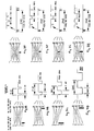
- Figure 3 illustrates some of the signal patterns appearing at the common diode cathode point for various blockage conditions.
- Figures 3A to 3D illustrate the waveforms to be expected for single or double blockages at either end (near the transmitter or receiver respectively) of the system.
- Figure 3 E illustrates the signal pattern to be expected for a small blockage in the 'D' beam path. This shows the 2mS gap; caused by the blockage of the Tx'D' as received when receiver 'D r ' is gated open. Note that narrower pulses may be apparent as the receiver time slot 'scans' through the Tx'D' time slot producing a group of pulses having a maximum pulse width of 2mS, spaced 8mS apart with a group repetition rate of 42 kHz (the difference between the sequence rates). Since no pulse is wider than 2mS, the system will have a slow alarm response.
- Figure 3F illustrates a small blockage at a beam crossing point of two adjacent transmitters. This results in a 3mS pulse and not a 4mS pulse as may be expected because receiver 'C r ' or 'D r ' can only receive for a 3mS period. (This would not be the case if the two sequences were in opposite directions). Since no pulse is wider than 3.5mS the system will have a slow alarm response.
- Figure 3G illustrates the same small blockage at the mid-crossing point of all four transmitters and again the widest pulse is only 3mS wide to give a slow alarm response.
- Figure 3H illustrates a blockage wider than the distance between any two heads.
- two adjacent receiver time slots of 6mS allow two blockage signals from adjacent transmitters to produce a group of pulses having a maximum width of 4mS.
- the 3mS or longer pulse-width detector and following delay circuit will give a fast alarm response.
- three band pass filters may be arranged to respond to the frequencies of pulses or groups of pulses that appear at the common point. For example: a blockage of one, two or three (but not four) transmitters will produce a pulse stream having a frequency of 125Hz, the transmitter repetition rate. A blockage of one, two or three (but not four) receivers will produce a pulse stream having a frequency of 83Hz, the receiver repetition rate. A blockage at a mid-way point within the network will produce pulse groups of 125Hz or 83Hz or combinations of both, at repetition rates of 42Hz.
- frequency selective filters 36, 38, 40 By feeding these signals to frequency selective filters 36, 38, 40, it is possible to signal whether the blockage is at either end or somewhere between. Further signal analysis using microcontrollers to store and compare individual receiver head pulse streams allows more precise location and sizing of blocking objects by means of triangulation.
- the transmitter heads' transmissions is identifiable (for example by transmitting at a different power, frequency or after a brief gap)
- signal processing of the received pulses allows the height of a blockage to be determined (i.e. its vertical position - for a vertically aligned array of transmitters/receivers).
Landscapes
- Physics & Mathematics (AREA)
- General Physics & Mathematics (AREA)
- Burglar Alarm Systems (AREA)
- Geophysics And Detection Of Objects (AREA)
Claims (14)
- Appareil de détection d'intrusion comportant une unité d'émission ayant une pluralité d'émetteurs, un contrôleur d'émetteurs utilisable pour amener les émetteurs à émettre dans une séquence prédéterminée à une cadence d'émission prédéterminée, une unité de réception ayant une pluralité de récepteurs espacés des émetteurs, et un contrôleur de récepteurs utilisable pour lire les sorties des récepteurs dans une séquence prédéterminée à une cadence de réception prédéterminée, les cadences d'émission et de réception étant des cadences différentes.
- Appareil selon la revendication 1, dans lequel lesdits émetteurs sont agencés dans un boítier d'émission, et lesdits récepteurs sont agencés dans un boítier de réception séparé du boítier d'émission.
- Appareil selon la revendication 2, dans lequel les boítiers d'émission et de réception ne sont pas couplés électriquement ensemble.
- Appareil selon l'une quelconque des revendications précédentes, dans lequel le contrôleur d'émetteurs est agencé de telle sorte que la séquence d'émission prédéterminée amène les émetteurs situés à proximité les uns des autres à être activés consécutivement.
- Appareil selon l'une quelconque des revendications précédentes, dans lequel le contrôleur de récepteurs est agencé de telle sorte que la séquence de réception prédéterminée amène les récepteurs situés à proximité les uns des autres à être lus consécutivement.
- Appareil selon l'une quelconque des revendications précédentes, dans lequel le contrôleur de récepteurs est agencé de telle sorte que, en utilisation, chaque émetteur respectif émet pendant sensiblement la même période.
- Appareil selon l'une quelconque des revendications précédentes, dans lequel le contrôleur d'émetteurs est agencé de telle sorte qu'il n'existe pratiquement aucun intervalle entre des émissions d'émetteurs consécutifs.
- Appareil selon l'une quelconque des revendications 1 à 5, dans lequel le contrôleur de récepteurs est agencé de telle sorte que des émissions d'un des émetteurs sont émises à un niveau de puissance différent et/ou avant ou après un intervalle dans la séquence d'émission de telle sorte que l'émission de l'émetteur est identifiable par le contrôleur de récepteurs.
- Appareil selon l'une quelconque des revendications précédentes, dans lequel les sorties des récepteurs sont combinées par une opération OU et le contrôleur de récepteurs est utilisable pour détecter un changement du niveau logique de la sortie ayant subi une opération OU des récepteurs ayant sensiblement une durée prédéterminée.
- Appareil selon la revendication 9, dans lequel une condition d'alarme est donnée après qu'un nombre prédéterminé de niveaux logiques modifiés ayant la durée prédéterminée ait été détecté.
- Appareil selon l'une quelconque des revendications précédentes, comportant des moyens pour indiquer la position d'un obstacle se trouvant dans le champ d'observation desdits émetteurs.
- Appareil selon l'une quelconque des revendications précédentes, dans lequel les sorties des récepteurs sont combinées par une opération OU et le contrôleur de récepteurs est utilisable pour détecter un changement du niveau logique de la sortie ayant subi une opération OU des récepteurs survenant sensiblement à une cadence de répétition prédéterminée.
- Appareil selon la revendication 12, dans lequel une indication de la position latérale d'un obstacle entre l'émetteur et le récepteur est donnée conformément à ladite cadence de répétition.
- Appareil selon l'une quelconque des revendications précédentes, dans lequel les émetteurs et les récepteurs sont utilisables pour émettre et recevoir respectivement dans le spectre infrarouge.
Applications Claiming Priority (2)
| Application Number | Priority Date | Filing Date | Title |
|---|---|---|---|
| GB9725027 | 1997-11-26 | ||
| GBGB9725027.8A GB9725027D0 (en) | 1997-11-26 | 1997-11-26 | Infra red intrusion detection system |
Publications (3)
| Publication Number | Publication Date |
|---|---|
| EP0919969A2 EP0919969A2 (fr) | 1999-06-02 |
| EP0919969A3 EP0919969A3 (fr) | 2000-05-03 |
| EP0919969B1 true EP0919969B1 (fr) | 2003-07-02 |
Family
ID=10822690
Family Applications (1)
| Application Number | Title | Priority Date | Filing Date |
|---|---|---|---|
| EP98309021A Expired - Lifetime EP0919969B1 (fr) | 1997-11-26 | 1998-11-04 | Système de détection d'intrusion à infrarouge |
Country Status (4)
| Country | Link |
|---|---|
| EP (1) | EP0919969B1 (fr) |
| AT (1) | ATE244433T1 (fr) |
| DE (1) | DE69816001D1 (fr) |
| GB (1) | GB9725027D0 (fr) |
Families Citing this family (3)
| Publication number | Priority date | Publication date | Assignee | Title |
|---|---|---|---|---|
| ITTO20010587A1 (it) * | 2001-06-18 | 2002-12-18 | Giuseppe Mallarino | Dispositivo rivelatore a barriera. |
| JP2003091784A (ja) | 2001-09-19 | 2003-03-28 | Optex Co Ltd | 多段式能動型赤外線センサ |
| US8829441B2 (en) | 2011-03-21 | 2014-09-09 | Brian McLaughlin | Tailgate detection using infra-red beams |
Family Cites Families (5)
| Publication number | Priority date | Publication date | Assignee | Title |
|---|---|---|---|---|
| DE3803033A1 (de) * | 1988-02-02 | 1989-08-10 | Sick Erwin Gmbh | Lichtschrankengitter |
| EP0563516A3 (en) * | 1992-01-17 | 1995-03-22 | Control Card Srl | Optical barrier for detecting moving objects |
| ATE195190T1 (de) * | 1992-04-30 | 2000-08-15 | Reer Spa | Optoelektronische schranke |
| GB9311933D0 (en) * | 1993-06-09 | 1993-07-28 | Intelsec Systems Ltd | Detector systems |
| DE4338978C2 (de) * | 1993-11-15 | 1998-05-07 | Sick Ag | Verfahren zur Feststellung defekter Lichtsender und/oder Lichtempfänger eines Lichtgitters und Lichtgitter |
-
1997
- 1997-11-26 GB GBGB9725027.8A patent/GB9725027D0/en not_active Ceased
-
1998
- 1998-11-04 DE DE69816001T patent/DE69816001D1/de not_active Expired - Lifetime
- 1998-11-04 EP EP98309021A patent/EP0919969B1/fr not_active Expired - Lifetime
- 1998-11-04 AT AT98309021T patent/ATE244433T1/de not_active IP Right Cessation
Also Published As
| Publication number | Publication date |
|---|---|
| EP0919969A2 (fr) | 1999-06-02 |
| GB9725027D0 (en) | 1998-01-28 |
| DE69816001D1 (de) | 2003-08-07 |
| ATE244433T1 (de) | 2003-07-15 |
| EP0919969A3 (fr) | 2000-05-03 |
Similar Documents
| Publication | Publication Date | Title |
|---|---|---|
| US6806811B1 (en) | Infra-red perimeter alarm | |
| US6712269B1 (en) | Counting apparatus | |
| EP0093463A1 (fr) | Système, procédé et appareil pour la protection des objets, individus et matière | |
| WO2003075491A2 (fr) | Systeme d'alignement | |
| CA2089356A1 (fr) | Dispositif de surveillance, notamment des plaques d'immitraculation de vehicules automobiles | |
| US4551710A (en) | Method and apparatus for reporting dangerous conditions | |
| EP0919969B1 (fr) | Système de détection d'intrusion à infrarouge | |
| US6919567B2 (en) | Active infrared sensor | |
| EP1369833B1 (fr) | Système de sécurité pour surveiller le passage d'articles | |
| US5450062A (en) | Detection system with reduced sensitivity to pin diode effect | |
| EP0148190B1 (fr) | Systeme de protection antivol en particulier pour magasins | |
| EP0129577B1 (fr) | Ecran lumineux commande par microprocesseur | |
| EP1118881A2 (fr) | Dispositif capteur opto-électronique et procédé pour l'opération d'un dispositif capteur électronique | |
| JP4467254B2 (ja) | 監視装置 | |
| JPH0772752B2 (ja) | 赤外線警戒装置 | |
| JPS60142498A (ja) | 光線式警戒装置 | |
| SU763933A1 (ru) | Оптико-электронное устройство охранной сигнализации | |
| CN1191915C (zh) | 多路红外光电安全检测方法及装置 | |
| KR102203931B1 (ko) | 레이저와 재귀반사체를 이용한 침입자 검출 시스템 및 이를 이용한 칩입자 검출 방법 | |
| GB2129123A (en) | Intruder detector and method | |
| CA1304468C (fr) | Deblocage selectif de circuits verrouilles | |
| RU2128858C1 (ru) | Оптико-электронное устройство сигнализации и контроля | |
| KR100600622B1 (ko) | 다중 빔 적외선 센서 및 그의 운용방법 | |
| SU934519A1 (ru) | Устройство дл охранной сигнализации | |
| JPS6139193A (ja) | 光線式警戒装置 |
Legal Events
| Date | Code | Title | Description |
|---|---|---|---|
| PUAI | Public reference made under article 153(3) epc to a published international application that has entered the european phase |
Free format text: ORIGINAL CODE: 0009012 |
|
| AK | Designated contracting states |
Kind code of ref document: A2 Designated state(s): AT BE CH DE DK ES FI FR GB GR IE IT LI NL PT SE |
|
| AX | Request for extension of the european patent |
Free format text: AL;LT;LV;MK;RO;SI |
|
| PUAL | Search report despatched |
Free format text: ORIGINAL CODE: 0009013 |
|
| AK | Designated contracting states |
Kind code of ref document: A3 Designated state(s): AT BE CH CY DE DK ES FI FR GB GR IE IT LI LU MC NL PT SE |
|
| AX | Request for extension of the european patent |
Free format text: AL;LT;LV;MK;RO;SI |
|
| 17P | Request for examination filed |
Effective date: 20000602 |
|
| AKX | Designation fees paid |
Free format text: AT BE CH DE DK ES FI FR GB GR IE IT LI NL PT SE |
|
| GRAH | Despatch of communication of intention to grant a patent |
Free format text: ORIGINAL CODE: EPIDOS IGRA |
|
| RAP1 | Party data changed (applicant data changed or rights of an application transferred) |
Owner name: SECURITY ENCLOSURES LIMITED |
|
| GRAH | Despatch of communication of intention to grant a patent |
Free format text: ORIGINAL CODE: EPIDOS IGRA |
|
| GRAA | (expected) grant |
Free format text: ORIGINAL CODE: 0009210 |
|
| AK | Designated contracting states |
Designated state(s): AT BE CH DE DK ES FI FR GB GR IE IT LI NL PT SE |
|
| PG25 | Lapsed in a contracting state [announced via postgrant information from national office to epo] |
Ref country code: NL Free format text: LAPSE BECAUSE OF FAILURE TO SUBMIT A TRANSLATION OF THE DESCRIPTION OR TO PAY THE FEE WITHIN THE PRESCRIBED TIME-LIMIT Effective date: 20030702 Ref country code: LI Free format text: LAPSE BECAUSE OF FAILURE TO SUBMIT A TRANSLATION OF THE DESCRIPTION OR TO PAY THE FEE WITHIN THE PRESCRIBED TIME-LIMIT Effective date: 20030702 Ref country code: FI Free format text: LAPSE BECAUSE OF FAILURE TO SUBMIT A TRANSLATION OF THE DESCRIPTION OR TO PAY THE FEE WITHIN THE PRESCRIBED TIME-LIMIT Effective date: 20030702 Ref country code: ES Free format text: LAPSE BECAUSE OF FAILURE TO SUBMIT A TRANSLATION OF THE DESCRIPTION OR TO PAY THE FEE WITHIN THE PRESCRIBED TIME-LIMIT Effective date: 20030702 Ref country code: CH Free format text: LAPSE BECAUSE OF FAILURE TO SUBMIT A TRANSLATION OF THE DESCRIPTION OR TO PAY THE FEE WITHIN THE PRESCRIBED TIME-LIMIT Effective date: 20030702 Ref country code: BE Free format text: LAPSE BECAUSE OF FAILURE TO SUBMIT A TRANSLATION OF THE DESCRIPTION OR TO PAY THE FEE WITHIN THE PRESCRIBED TIME-LIMIT Effective date: 20030702 Ref country code: AT Free format text: LAPSE BECAUSE OF FAILURE TO SUBMIT A TRANSLATION OF THE DESCRIPTION OR TO PAY THE FEE WITHIN THE PRESCRIBED TIME-LIMIT Effective date: 20030702 |
|
| REG | Reference to a national code |
Ref country code: GB Ref legal event code: FG4D |
|
| REG | Reference to a national code |
Ref country code: CH Ref legal event code: EP |
|
| REG | Reference to a national code |
Ref country code: IE Ref legal event code: FG4D |
|
| REF | Corresponds to: |
Ref document number: 69816001 Country of ref document: DE Date of ref document: 20030807 Kind code of ref document: P |
|
| PG25 | Lapsed in a contracting state [announced via postgrant information from national office to epo] |
Ref country code: SE Free format text: LAPSE BECAUSE OF FAILURE TO SUBMIT A TRANSLATION OF THE DESCRIPTION OR TO PAY THE FEE WITHIN THE PRESCRIBED TIME-LIMIT Effective date: 20031002 Ref country code: PT Free format text: LAPSE BECAUSE OF FAILURE TO SUBMIT A TRANSLATION OF THE DESCRIPTION OR TO PAY THE FEE WITHIN THE PRESCRIBED TIME-LIMIT Effective date: 20031002 Ref country code: GR Free format text: LAPSE BECAUSE OF FAILURE TO SUBMIT A TRANSLATION OF THE DESCRIPTION OR TO PAY THE FEE WITHIN THE PRESCRIBED TIME-LIMIT Effective date: 20031002 Ref country code: DK Free format text: LAPSE BECAUSE OF FAILURE TO SUBMIT A TRANSLATION OF THE DESCRIPTION OR TO PAY THE FEE WITHIN THE PRESCRIBED TIME-LIMIT Effective date: 20031002 |
|
| PG25 | Lapsed in a contracting state [announced via postgrant information from national office to epo] |
Ref country code: DE Free format text: LAPSE BECAUSE OF FAILURE TO SUBMIT A TRANSLATION OF THE DESCRIPTION OR TO PAY THE FEE WITHIN THE PRESCRIBED TIME-LIMIT Effective date: 20031003 |
|
| PG25 | Lapsed in a contracting state [announced via postgrant information from national office to epo] |
Ref country code: IE Free format text: LAPSE BECAUSE OF NON-PAYMENT OF DUE FEES Effective date: 20031104 |
|
| NLV1 | Nl: lapsed or annulled due to failure to fulfill the requirements of art. 29p and 29m of the patents act | ||
| REG | Reference to a national code |
Ref country code: CH Ref legal event code: PL |
|
| PLBE | No opposition filed within time limit |
Free format text: ORIGINAL CODE: 0009261 |
|
| STAA | Information on the status of an ep patent application or granted ep patent |
Free format text: STATUS: NO OPPOSITION FILED WITHIN TIME LIMIT |
|
| ET | Fr: translation filed | ||
| 26N | No opposition filed |
Effective date: 20040405 |
|
| REG | Reference to a national code |
Ref country code: IE Ref legal event code: MM4A |
|
| REG | Reference to a national code |
Ref country code: GB Ref legal event code: 732E |
|
| REG | Reference to a national code |
Ref country code: FR Ref legal event code: TP |
|
| REG | Reference to a national code |
Ref country code: FR Ref legal event code: RM |
|
| PGFP | Annual fee paid to national office [announced via postgrant information from national office to epo] |
Ref country code: GB Payment date: 20121102 Year of fee payment: 15 Ref country code: IT Payment date: 20121127 Year of fee payment: 15 |
|
| PGFP | Annual fee paid to national office [announced via postgrant information from national office to epo] |
Ref country code: FR Payment date: 20121220 Year of fee payment: 15 |
|
| GBPC | Gb: european patent ceased through non-payment of renewal fee |
Effective date: 20131104 |
|
| REG | Reference to a national code |
Ref country code: FR Ref legal event code: ST Effective date: 20140731 |
|
| PG25 | Lapsed in a contracting state [announced via postgrant information from national office to epo] |
Ref country code: IT Free format text: LAPSE BECAUSE OF NON-PAYMENT OF DUE FEES Effective date: 20131104 |
|
| PG25 | Lapsed in a contracting state [announced via postgrant information from national office to epo] |
Ref country code: FR Free format text: LAPSE BECAUSE OF NON-PAYMENT OF DUE FEES Effective date: 20131202 Ref country code: GB Free format text: LAPSE BECAUSE OF NON-PAYMENT OF DUE FEES Effective date: 20131104 |