EP0919769B1 - Vorrichtung zum Schutz der Einspritzdüsenspitze eines Brenners und diese enthaltende Heizanlage - Google Patents
Vorrichtung zum Schutz der Einspritzdüsenspitze eines Brenners und diese enthaltende Heizanlage Download PDFInfo
- Publication number
- EP0919769B1 EP0919769B1 EP98402658A EP98402658A EP0919769B1 EP 0919769 B1 EP0919769 B1 EP 0919769B1 EP 98402658 A EP98402658 A EP 98402658A EP 98402658 A EP98402658 A EP 98402658A EP 0919769 B1 EP0919769 B1 EP 0919769B1
- Authority
- EP
- European Patent Office
- Prior art keywords
- burner
- heat shield
- jacket
- sio
- burner according
- Prior art date
- Legal status (The legal status is an assumption and is not a legal conclusion. Google has not performed a legal analysis and makes no representation as to the accuracy of the status listed.)
- Expired - Lifetime
Links
Images

Classifications
-
- F—MECHANICAL ENGINEERING; LIGHTING; HEATING; WEAPONS; BLASTING
- F23—COMBUSTION APPARATUS; COMBUSTION PROCESSES
- F23C—METHODS OR APPARATUS FOR COMBUSTION USING FLUID FUEL OR SOLID FUEL SUSPENDED IN A CARRIER GAS OR AIR
- F23C5/00—Disposition of burners with respect to the combustion chamber or to one another; Mounting of burners in combustion apparatus
- F23C5/02—Structural details of mounting
-
- F—MECHANICAL ENGINEERING; LIGHTING; HEATING; WEAPONS; BLASTING
- F23—COMBUSTION APPARATUS; COMBUSTION PROCESSES
- F23D—BURNERS
- F23D14/00—Burners for combustion of a gas, e.g. of a gas stored under pressure as a liquid
- F23D14/46—Details
- F23D14/72—Safety devices, e.g. operative in case of failure of gas supply
- F23D14/76—Protecting flame and burner parts
Definitions
- the present invention relates to an output protection device ejection of a burner mounted through a wall of an oven, of the type comprising a peripheral heat shield and mounting means said heat shield around the burner ejection outlet.
- the invention also relates to a heating device comprising a burner and a protection device of the aforementioned type.
- the invention relates more particularly to a burner according to the preamble of claim 1.
- the burners used are subject to strong attacks due on the one hand to thermal radiation and on the other hand to attacks chemicals caused by bodies resulting from the melting of cast iron.
- these cooling means include a tubular protective member through which circulates cooling water. This tubular member is mounted axially at the end from the burner and protrudes inside the oven.
- EP-A-582 521 discloses a burner provided with a thermal screen made of refractory material.
- the object of the invention is to propose a burner comprising a device for protecting the burner ejection outlet and a heating device comprising such a burner, do not not having the disadvantages mentioned above, and which allows get rid of the existence of a bulky water circuit and source of malfunctions.
- the invention relates to a burner according to the preamble of claim 1 , characterized in that the screen thermal includes a consumable structure of refractory material having the shape of a sleeve whose position can be adjusted and which always exceeds the ejection end of the burner by a same distance.
- the invention further relates to a heating device comprising a burner associated with a protection device as defined above.
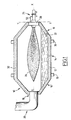
- FIG. 1 a rotary furnace 10 for melting cast iron provided with a burner according to the invention.
- the oven has an enclosure 12 with axis of horizontal revolution, noted X-X.
- the enclosure 12 is delimited in its part running through a cylindrical wall 14 comprising, at each end 16, frustoconical obturation walls.
- the oven has axially means 20 for introducing the metals to be melted. It comprises, at its other end, an outlet 22 for molten iron.
- a burner 24 adapted to produce a flame 26 along the axis of the oven.
- the burner 24 is carried by a shutter door 28 of the oven articulated around a vertical Y-Y axis.
- the oven is supported in its running part by two crowns of rollers 30. It further comprises rotational drive means not shown.
- the interior wall of the furnace is lined with a siliceous refractory lining 32 comprising approximately 95% by weight of SiO 2 and 4% by weight of Al 2 O 3 , the remainder consisting of impurities.
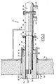
- the door-mounted burner is shown on a larger scale in Figures 2 and 3.
- the door has an outer metal wall 34 lined internally of a refractory material 36 similar to the coating 32 used for the interior wall of the oven.
- the burner comprises, in a conventional manner, an envelope or body 38, generally of revolution.
- This envelope is separated by a wall transverse 40 delimiting therein a fuel gas inlet chamber 42 arranged behind and an oxidizing gas inlet chamber 44.
- the latter leads to the front end of the body, directly inside of the oven through an opening 46.
- Each chamber 42, 44 is connected to a corresponding gas supply source, by a side connection, noted 42A and 44A respectively.
- the fuel gas inlet chamber 42 communicates with three fuel injection rods 48. These rods pass through the wall 40 and are carried by it. They extend into the following envelope 38 the axis of the burner and protrude beyond the opening 46.
- the burner casing 38 is fixedly connected to the plate 34 of the door by a support frame 50 shown schematically in the figures.
- the burner is associated with a device 52 for protection of the burner injection outlet.
- This device 52 essentially comprises a heat shield 54 carried by mounting means 56 of it on the cylindrical running part denoted 38A of the envelope.
- the heat shield 54 is formed of a tubular member or sleeve. Thus, it has an external cylindrical surface denoted 54A and a passage internal cylindrical 54B. The diameter of the latter is constant and is very slightly greater than the external diameter of the current portion 38A of the burner body.
- the sleeve passes through the lining 36 of the door through an opening cylindrical 36A.
- a skirt 57 for protecting the heat shield formed of a tubular wall, extends the cylindrical opening 36A and projects outside the oven.
- the skirt 57 is integral with the wall 34.
- Sleeve 54 projects inside the oven at one front end at a distance of 7 cm. Its rear end projects outside the oven beyond plate 34 of the door. This rear end is integral mounting means 56.
- the sleeve 54 is formed by an adobe having undergone, before assembly with the mounting means 56, a cooking step prior to a temperature above 1000 ° C.
- the refractory material constituting the sleeve 54 is an aluminosilicate advantageously comprising by mass x% of SiO 2 and y% of Al 2 O 3 , the ratio x / y being between one third and two thirds and advantageously close to one half.
- the sum x + y of the mass percentages of SiO 2 and Al 2 O 3 is greater than 90%.
- the sleeve 54 In order to ensure good resistance of the sleeve 54 to the flame, as well good resistance to thermal shock, especially during phases shutdown and start-up of the oven, the sleeve is made in the manner next.
- the materials in the form of aggregates constituting the structure of the sleeve are arranged in a cylindrical mold defining the shape of the sleeve to make an adobe.
- tamping or clamping the adobe in the mold is made with care, in particular by adding successive layers 2 or 3 cm thick each packed with a pneumatic gland.
- the cooking of the rammed earth is then carried out according to a standard profile of temperature rise specific to adobe to a temperature of 1350 ° C.
- the rammed earth After cooking and demoulding, the rammed earth has the following characteristics: Basic constituent fireclay Average expansion between 0 and 1000 ° C 3.10 6 Physical characteristics Density after heating to 1000 ° C 2.3 T / m 3 Conductivity coefficient in Kcal m 2 h ° C to 600 ° C 0.7 800 ° C 0.7 1200 ° C 1 Resistance to cold compression after heating to 1100 ° C 350 Kg / cm 2 Pyroscopic cone 36 Temperature limit for use 1500 ° C Slump under load of 2 bars 0.5% at 1200 ° C and 5% at 1340 ° C.
- the mounting means 56 are adapted to ensure movement of the heat shield 54 relative to the wall of the oven enters at least two positions spaced along the axis of the burner. They include for this purpose a guide tube 58 with an inside diameter slightly greater than the diameter external of the current part 38A of the envelope.
- the tube 58 comprises, at its front end, a transverse annular plate 60 provided with holes fixing the screen 54.
- the latter comprises inking 62 the threaded ends of which are received through bores and held in place by nuts 64.
- the tube 58 has an annular flange 66 drilled with a set of tapped holes. Against this flange is applied an additional flange 68 retained on the first flange 66 by screws 70 forming means for tightening the two flanges against each other according to the axis of the burner.
- the flange 68 has at its internal diameter, on its face in contact with the first flange 66, a countersink 72 in which is received a clamping O-ring 74 whose diameter corresponds substantially to outside diameter of the current part 38A of the envelope. So the joint O-ring 74 is in contact with the lateral surface of the envelope.
- the clamping means 70 hold the flange 68 against the flange 66, the seal 74 is compressed and exerts a friction force on the main part 38A of the envelope, ensuring that the position of the heat shield 54.
- this length is of the order of 7 cm.
- the sleeve 54 When the sleeve 54 is new, as shown in FIG. 2, it has a great length, for example equal to 40 cm. So, the mounting means 56 are held behind and most of the length of the sleeve 54 extends behind the lining 36.
- the annular end face of the sleeve contained inside the oven gradually degrades, in particular under the chemical action of iron and manganese oxide molecules produced by the slag resulting from molten iron.
- the erosion of the end front of the sleeve is carried out along a plane extending perpendicularly to the axis of it. So in order to keep constant the length of the part of the sleeve projecting from the lining 36, the user of the oven periodically advances the sleeve to compensate for the amount of material eroded at its end.
- the low cost of the sleeve allows it to be replaced several times during the life of the oven without significantly increasing the cost operating it.
Landscapes
- Engineering & Computer Science (AREA)
- Chemical & Material Sciences (AREA)
- Combustion & Propulsion (AREA)
- Mechanical Engineering (AREA)
- General Engineering & Computer Science (AREA)
- Vertical, Hearth, Or Arc Furnaces (AREA)
- Muffle Furnaces And Rotary Kilns (AREA)
- Furnace Housings, Linings, Walls, And Ceilings (AREA)
- Blast Furnaces (AREA)
- Gas Burners (AREA)
- Pre-Mixing And Non-Premixing Gas Burner (AREA)
- Cookers (AREA)
- Compositions Of Oxide Ceramics (AREA)
Claims (9)
- Brenner mit einem Mantel (38), der Leitungen (34, 48) zur Zufuhr des Brennstoffes und des Oxidationsmittels einschließt und an seinem Ausstoßauslass mit einer Hitzeschild-Schutzvorrichtung versehen ist, dadurch gekennzeichnet, dass der Hitzeschild (54) eine verzehrbare Konstruktion aus feuerfestem Material enthält, die die Form einer Hülse (54) aufweist, deren Position so eingestellt werden kann, dass sie das Ausstoßende des Brenners immer um eine gleiche Strecke übertrifft.
- Brenner nach Anspruch 2, dadurch gekennzeichnet, dass er Mittel zur Verschiebung des Hitzeschildes (54) aufweist.
- Brenner nach Anspruch 1 oder 2, dadurch gekennzeichnet, dass er Montagemittel (56) aufweist, die so zwischen dem Brennerkörper (24) und dem Hitzeschild (54) angeordnet sind, dass der Hitzeschild von dem Brenner (24) getragen wird.
- Brenner nach Anspruch 2 oder 3, dadurch gekennzeichnet, dass der Mantel (38) über mindestens einen Teil seiner Länge röhrenförmig ist und dass die Verschiebungsmittel ein Führungsglied (58) aufweisen, das auf dem röhrenförmigen Teil (38A) des Mantels aufgepresst ist, so dass der Hitzeschild (54) auf dem Mantel (38) verschoben werden kann.
- Brenner nach Anspruch 4, dadurch gekennzeichnet, dass das Führungsglied (58) mit zwei angekuppelten Flanschen (66, 68), die eine einspannbare O-Ring-Dichtung (74) einklemmen, welche gegen die Außenfläche des röhrenförmigen Teils (38A) des Mantels (38) gedrückt wird, sowie mit Mitteln (70) zum Anziehen der beiden Flansche aneinander, um die O-Ring-Dichtung (74) zu komprimieren und somit zu gewährleisten, dass der Hitzeschild (54) bezüglich des Brennermantels (38) in Position gehalten wird, versehen ist.
- Brenner nach einem der vorhergehenden Ansprüche, dadurch gekennzeichnet, dass das die Konstruktion bildende feuerfeste Material ein Aluminosilicat aus x Masse-% SiO2 und y Masse-% Al2O3 mit einem Verhältnis x/y zwischen einem Drittel und zwei Dritteln und insbesondere nahe Einhalb ist.
- Brenner nach Anspruch 6, dadurch gekennzeichnet, dass die Summe x + y der Massenprozente von SIO2 und AL2O3 über 90% liegt.
- Brenner nach Anspruch 6 oder 7, dadurch gekennzeichnet, dass die Konstruktion aus einer Stampfmasse besteht, die vor der Montage einem Brennschritt bei einer Temperatur von über 1000°C unterzogen wurde.
- Heizvorrichtung, die einen Brenner (24) nach einem der vorhergehenden Ansprüche umfasst, der zur Montage (28) durch die Wand eines Ofens ausgeführt ist.
Applications Claiming Priority (2)
| Application Number | Priority Date | Filing Date | Title |
|---|---|---|---|
| FR9715089 | 1997-12-01 | ||
| FR9715089A FR2771799B1 (fr) | 1997-12-01 | 1997-12-01 | Dispositif de protection de l'extremite d'injection d'un bruleur et dispositif de chauffe le comportant |
Publications (2)
| Publication Number | Publication Date |
|---|---|
| EP0919769A1 EP0919769A1 (de) | 1999-06-02 |
| EP0919769B1 true EP0919769B1 (de) | 2003-07-02 |
Family
ID=9514002
Family Applications (1)
| Application Number | Title | Priority Date | Filing Date |
|---|---|---|---|
| EP98402658A Expired - Lifetime EP0919769B1 (de) | 1997-12-01 | 1998-10-26 | Vorrichtung zum Schutz der Einspritzdüsenspitze eines Brenners und diese enthaltende Heizanlage |
Country Status (12)
| Country | Link |
|---|---|
| US (1) | US6089858A (de) |
| EP (1) | EP0919769B1 (de) |
| JP (1) | JPH11229009A (de) |
| KR (1) | KR19990062680A (de) |
| AR (1) | AR017774A1 (de) |
| BR (1) | BR9805317A (de) |
| DE (1) | DE69816000T2 (de) |
| ES (1) | ES2203908T3 (de) |
| FR (1) | FR2771799B1 (de) |
| PL (1) | PL330003A1 (de) |
| PT (1) | PT919769E (de) |
| WO (1) | WO1999028676A1 (de) |
Families Citing this family (5)
| Publication number | Priority date | Publication date | Assignee | Title |
|---|---|---|---|---|
| US6688881B1 (en) * | 2002-08-09 | 2004-02-10 | Fitel Usa Corp. | Torch mount for high deposition glass torches |
| US6884064B1 (en) | 2003-11-12 | 2005-04-26 | Khd Humboldt Wedag Ag | Burner mechanism for a rotary kiln |
| CN104846162A (zh) * | 2015-05-11 | 2015-08-19 | 夏云美 | 一种淬火用火焰喷射管 |
| CN109595547A (zh) * | 2017-09-30 | 2019-04-09 | 山东博研粉体技术装备有限公司 | 一种双膛窑喷枪 |
| RU2755239C1 (ru) | 2021-03-02 | 2021-09-14 | Общество с ограниченной ответственностью "ЭР ЛИКИД" | Топливно-кислородная горелка для плавильной печи, система и способ управления розжигом и контролем пламени такой горелки |
Family Cites Families (8)
| Publication number | Priority date | Publication date | Assignee | Title |
|---|---|---|---|---|
| US1930812A (en) * | 1931-11-13 | 1933-10-17 | Gilbert & Barker Mfg Co | Oil burner |
| US4726763A (en) * | 1982-09-24 | 1988-02-23 | Gte Products Corporation | Dual insulated ceramic burner |
| US4952218A (en) * | 1988-08-26 | 1990-08-28 | The Dow Chemical Company | Two-fluid nozzle for atomizing a liquid solid slurry and protecting nozzle tip |
| US4986748A (en) * | 1989-12-15 | 1991-01-22 | Corning Incorporated | Wide range oxy-fuel burner and furnace operation |
| US5267850A (en) * | 1992-06-04 | 1993-12-07 | Praxair Technology, Inc. | Fuel jet burner |
| FR2694623B1 (fr) * | 1992-08-06 | 1994-09-16 | Air Liquide | Brûleurs oxycombustibles. |
| GB2280501B (en) * | 1993-07-30 | 1996-10-23 | Co Steel Sheerness Plc | Burner mounting device |
| US5785721A (en) * | 1997-01-31 | 1998-07-28 | Texaco Inc. | Fuel injector nozzle with preheat sheath for reducing thermal shock damage |
-
1997
- 1997-12-01 FR FR9715089A patent/FR2771799B1/fr not_active Expired - Fee Related
-
1998
- 1998-10-26 EP EP98402658A patent/EP0919769B1/de not_active Expired - Lifetime
- 1998-10-26 DE DE69816000T patent/DE69816000T2/de not_active Expired - Lifetime
- 1998-10-26 ES ES98402658T patent/ES2203908T3/es not_active Expired - Lifetime
- 1998-10-26 PT PT98402658T patent/PT919769E/pt unknown
- 1998-11-27 JP JP10337906A patent/JPH11229009A/ja active Pending
- 1998-11-30 AR ARP980106059A patent/AR017774A1/es unknown
- 1998-11-30 BR BR9805317-5A patent/BR9805317A/pt not_active Application Discontinuation
- 1998-12-01 KR KR1019980052161A patent/KR19990062680A/ko not_active Withdrawn
- 1998-12-01 PL PL98330003A patent/PL330003A1/xx unknown
- 1998-12-02 US US09/319,248 patent/US6089858A/en not_active Expired - Fee Related
- 1998-12-02 WO PCT/PT1998/000006 patent/WO1999028676A1/en not_active Ceased
Also Published As
| Publication number | Publication date |
|---|---|
| DE69816000D1 (de) | 2003-08-07 |
| DE69816000T2 (de) | 2004-05-27 |
| PT919769E (pt) | 2003-11-28 |
| ES2203908T3 (es) | 2004-04-16 |
| BR9805317A (pt) | 1999-11-09 |
| KR19990062680A (ko) | 1999-07-26 |
| FR2771799A1 (fr) | 1999-06-04 |
| JPH11229009A (ja) | 1999-08-24 |
| US6089858A (en) | 2000-07-18 |
| FR2771799B1 (fr) | 1999-12-31 |
| PL330003A1 (en) | 1999-06-07 |
| EP0919769A1 (de) | 1999-06-02 |
| AR017774A1 (es) | 2001-10-24 |
| WO1999028676A1 (en) | 1999-06-10 |
Similar Documents
| Publication | Publication Date | Title |
|---|---|---|
| EP0296032B1 (de) | Verbrennungssystem mit hoher Abgasaustrittsgeschwindigkeit | |
| EP0624051A1 (de) | Mikrowellenofen, insbesondere zum schnellen Heizen bei hohen Temperaturen | |
| EP0919769B1 (de) | Vorrichtung zum Schutz der Einspritzdüsenspitze eines Brenners und diese enthaltende Heizanlage | |
| CA2070506A1 (fr) | Dispositif de refroidissement d'une goulotte de distribution d'une installation de chargement d'un four a cuve | |
| EP0646751A1 (de) | Brenner und deren Anwendung in einem Glasofen | |
| EP0875319B1 (de) | Zwischengefäss mit mindestens einem Plasmabrenner für die Wiederaufheizung von geschmolzenen Metallen | |
| EP0921350A1 (de) | Sauerstoff-Brennstoffbrenner | |
| FR2597578A1 (fr) | Appareil a bruleur, notamment chauffe-eau, muni d'une soufflante | |
| EP0183631A1 (de) | Wandelektrode für einen elektrischen Gleichstromhüttenofen | |
| EP1007883A1 (de) | Einäscherungsverfahren und kremationsofen | |
| EP0069654B1 (de) | Zündvorrichtung für einen Fackelbrenner | |
| FR2676799A1 (fr) | Dispositif d'etancheite partielle entre l'interieur et l'exterieur d'un four a arc. | |
| FR2727744A1 (fr) | Bruleur a materiau combustible solide et installation comprenant un tel bruleur | |
| EP0082073A1 (de) | Verfahren und Vorrichtung zum Brennen von feuerfesten Auskleidungen | |
| BE1004612A6 (fr) | Dispositif de prechauffage d'une busette de coulee d'un metal en fusion. | |
| EP0073168A2 (de) | Brenner zum Schneiden, Schweissen oder Erwärmen | |
| EP0750450B1 (de) | Plasmabrenner mit einer wesentlich axisymmetrischen allgemeinen Struktur | |
| EP0406208B1 (de) | Vorrichtung zum Vorheizen einer Giessdüse für geschmolzenes Metall und mit dieser Vorrichtung ausgerüstete Metallgiesseinrichtung | |
| WO1991001077A1 (fr) | Torche a plasma | |
| EP0252843A1 (de) | Mechanisch beschickter, plasmabeheizter Drehrohrofen | |
| FR2683896A1 (fr) | Appareil pour le traitement thermique a haute temperature d'un corps solide divise. | |
| EP0750448A1 (de) | Vorrichtung zur Aussenkühlung eines Plasmabrenners | |
| FR2930981A1 (fr) | Chaudiere pour combustible solide, liquide ou pulverulent | |
| FR2750140A1 (fr) | Installation de vapocraquage avec moyens de protection contre l'erosion | |
| FR2632056A1 (fr) | Procede et dispositif pour la protection contre l'oxydation de tubes echangeurs thermiques |
Legal Events
| Date | Code | Title | Description |
|---|---|---|---|
| PUAI | Public reference made under article 153(3) epc to a published international application that has entered the european phase |
Free format text: ORIGINAL CODE: 0009012 |
|
| AK | Designated contracting states |
Kind code of ref document: A1 Designated state(s): BE CH DE ES IT LI NL PT |
|
| AX | Request for extension of the european patent |
Free format text: AL;LT;LV;MK;RO;SI |
|
| 17P | Request for examination filed |
Effective date: 19991202 |
|
| AKX | Designation fees paid |
Free format text: BE CH DE ES IT LI NL PT |
|
| 17Q | First examination report despatched |
Effective date: 20011017 |
|
| RAP1 | Party data changed (applicant data changed or rights of an application transferred) |
Owner name: L'AIR LIQUIDE, S.A. A DIRECTOIRE ET CONSEIL DE SUR |
|
| GRAH | Despatch of communication of intention to grant a patent |
Free format text: ORIGINAL CODE: EPIDOS IGRA |
|
| GRAH | Despatch of communication of intention to grant a patent |
Free format text: ORIGINAL CODE: EPIDOS IGRA |
|
| GRAA | (expected) grant |
Free format text: ORIGINAL CODE: 0009210 |
|
| AK | Designated contracting states |
Designated state(s): BE CH DE ES IT LI NL PT |
|
| REG | Reference to a national code |
Ref country code: CH Ref legal event code: EP |
|
| REF | Corresponds to: |
Ref document number: 69816000 Country of ref document: DE Date of ref document: 20030807 Kind code of ref document: P |
|
| REG | Reference to a national code |
Ref country code: ES Ref legal event code: FG2A Ref document number: 2203908 Country of ref document: ES Kind code of ref document: T3 |
|
| PLBE | No opposition filed within time limit |
Free format text: ORIGINAL CODE: 0009261 |
|
| STAA | Information on the status of an ep patent application or granted ep patent |
Free format text: STATUS: NO OPPOSITION FILED WITHIN TIME LIMIT |
|
| 26N | No opposition filed |
Effective date: 20040405 |
|
| PGFP | Annual fee paid to national office [announced via postgrant information from national office to epo] |
Ref country code: CH Payment date: 20131021 Year of fee payment: 16 |
|
| REG | Reference to a national code |
Ref country code: CH Ref legal event code: PL |
|
| PG25 | Lapsed in a contracting state [announced via postgrant information from national office to epo] |
Ref country code: CH Free format text: LAPSE BECAUSE OF NON-PAYMENT OF DUE FEES Effective date: 20141031 Ref country code: LI Free format text: LAPSE BECAUSE OF NON-PAYMENT OF DUE FEES Effective date: 20141031 |
|
| PGFP | Annual fee paid to national office [announced via postgrant information from national office to epo] |
Ref country code: DE Payment date: 20161020 Year of fee payment: 19 Ref country code: NL Payment date: 20161019 Year of fee payment: 19 |
|
| PGFP | Annual fee paid to national office [announced via postgrant information from national office to epo] |
Ref country code: PT Payment date: 20161024 Year of fee payment: 19 Ref country code: IT Payment date: 20161024 Year of fee payment: 19 Ref country code: BE Payment date: 20161019 Year of fee payment: 19 Ref country code: ES Payment date: 20161011 Year of fee payment: 19 |
|
| REG | Reference to a national code |
Ref country code: DE Ref legal event code: R119 Ref document number: 69816000 Country of ref document: DE |
|
| REG | Reference to a national code |
Ref country code: NL Ref legal event code: MM Effective date: 20171101 |
|
| PG25 | Lapsed in a contracting state [announced via postgrant information from national office to epo] |
Ref country code: DE Free format text: LAPSE BECAUSE OF NON-PAYMENT OF DUE FEES Effective date: 20180501 Ref country code: PT Free format text: LAPSE BECAUSE OF NON-PAYMENT OF DUE FEES Effective date: 20180426 Ref country code: NL Free format text: LAPSE BECAUSE OF NON-PAYMENT OF DUE FEES Effective date: 20171101 |
|
| REG | Reference to a national code |
Ref country code: BE Ref legal event code: MM Effective date: 20171031 |
|
| PG25 | Lapsed in a contracting state [announced via postgrant information from national office to epo] |
Ref country code: BE Free format text: LAPSE BECAUSE OF NON-PAYMENT OF DUE FEES Effective date: 20171031 |
|
| PG25 | Lapsed in a contracting state [announced via postgrant information from national office to epo] |
Ref country code: IT Free format text: LAPSE BECAUSE OF NON-PAYMENT OF DUE FEES Effective date: 20171026 |
|
| REG | Reference to a national code |
Ref country code: ES Ref legal event code: FD2A Effective date: 20181221 |
|
| PG25 | Lapsed in a contracting state [announced via postgrant information from national office to epo] |
Ref country code: PT Free format text: LAPSE BECAUSE OF EXPIRATION OF PROTECTION Effective date: 20181106 |
|
| PG25 | Lapsed in a contracting state [announced via postgrant information from national office to epo] |
Ref country code: ES Free format text: LAPSE BECAUSE OF NON-PAYMENT OF DUE FEES Effective date: 20171027 |