EP0918722B1 - Device for feeding printed products to a delivery station - Google Patents
Device for feeding printed products to a delivery station Download PDFInfo
- Publication number
- EP0918722B1 EP0918722B1 EP97920483A EP97920483A EP0918722B1 EP 0918722 B1 EP0918722 B1 EP 0918722B1 EP 97920483 A EP97920483 A EP 97920483A EP 97920483 A EP97920483 A EP 97920483A EP 0918722 B1 EP0918722 B1 EP 0918722B1
- Authority
- EP
- European Patent Office
- Prior art keywords
- printed products
- point
- conveying path
- transporter units
- dispensing point
- Prior art date
- Legal status (The legal status is an assumption and is not a legal conclusion. Google has not performed a legal analysis and makes no representation as to the accuracy of the status listed.)
- Expired - Lifetime
Links
Images

Classifications
-
- B—PERFORMING OPERATIONS; TRANSPORTING
- B65—CONVEYING; PACKING; STORING; HANDLING THIN OR FILAMENTARY MATERIAL
- B65H—HANDLING THIN OR FILAMENTARY MATERIAL, e.g. SHEETS, WEBS, CABLES
- B65H29/00—Delivering or advancing articles from machines; Advancing articles to or into piles
- B65H29/003—Delivering or advancing articles from machines; Advancing articles to or into piles by grippers
-
- B—PERFORMING OPERATIONS; TRANSPORTING
- B65—CONVEYING; PACKING; STORING; HANDLING THIN OR FILAMENTARY MATERIAL
- B65H—HANDLING THIN OR FILAMENTARY MATERIAL, e.g. SHEETS, WEBS, CABLES
- B65H29/00—Delivering or advancing articles from machines; Advancing articles to or into piles
- B65H29/02—Delivering or advancing articles from machines; Advancing articles to or into piles by mechanical grippers engaging the leading edge only of the articles
-
- B—PERFORMING OPERATIONS; TRANSPORTING
- B65—CONVEYING; PACKING; STORING; HANDLING THIN OR FILAMENTARY MATERIAL
- B65H—HANDLING THIN OR FILAMENTARY MATERIAL, e.g. SHEETS, WEBS, CABLES
- B65H2301/00—Handling processes for sheets or webs
- B65H2301/30—Orientation, displacement, position of the handled material
- B65H2301/32—Orientation of handled material
- B65H2301/323—Hanging
-
- B—PERFORMING OPERATIONS; TRANSPORTING
- B65—CONVEYING; PACKING; STORING; HANDLING THIN OR FILAMENTARY MATERIAL
- B65H—HANDLING THIN OR FILAMENTARY MATERIAL, e.g. SHEETS, WEBS, CABLES
- B65H2405/00—Parts for holding the handled material
- B65H2405/50—Gripping means
- B65H2405/55—Rail guided gripping means running in closed loop, e.g. without permanent interconnecting means
Definitions
- the present invention relates to a device for Supplying printed matter such as newspapers, Magazines, brochures and the like, as well as supplements to such printed matter, to a delivery point according to the preamble of claim 1.
- DE-B-1 153 383 describes a device for depositing of printed matter at high speed and at irregular intervals of one Rotary printing machine are known.
- the of the rotary printing press ejected without interruption Printed products are made using a Conveyed to a transfer point of the printed matter of a conveyor arrangement to be handed over to a customer Delivery point brings.
- the conveyor arrangement has individual Grippers rotating along a closed orbit whose mutual distance can be changed. After Takeover of a printed product are moving Grapples under the action of gravity along one Descent from the takeover point. To this Slope closes an approximately horizontal one Outlet section.
- the grippers go through both Discharge path as well as the upstream of this Section of the gradient with decreasing Speed, resulting in a downsizing of the mutual distance between the grippers leads.
- the grippers are separated from the outlet section Conveyor chain taken and by the latter on a web postponed what an opening of the gripper on the Delivery point and thus a release of the Results in printed products.
- the released Printed products are picked up at the delivery point by a another conveyor and taken over in package form transported away. In this known device takes place an interruption in the delivery of printed matter not take place from the rotary printing press.
- the present invention is based on the object to create a device of the type mentioned at the outset, with which it is possible, despite the limited memory and Supply capacity of the product roll or stack serving as the source a downstream delivery point continuously To be able to supply printed matter.
- the buffer section the one supplied by the source Promotional printed matter to the delivery point Conveyor arrangement will be these printed matter transporting transport organs temporarily saved. The latter then become this buffer section continuously fed to the delivery point.
- the as Source serving product wrap or stack is exhausted and either against exchanged a new product wrap or again with new ones Printed products can be replenished during this Time the continuous supply of printed matter to the delivery point out of the buffer line be continued, with the buffer section in their length is reduced, because yes during the replacement of the product roll or refill the stack with no new ones Transport organs loaded with printed matter more for Buffer section arrive.
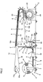
- the device shown in FIGS. 1 and 2 has one Delivery station 1 and a processing station 2, the are connected to each other via a conveyor arrangement 3.
- This conveyor arrangement 3 transports to even closer descriptive manner printed matter 4, namely Newspapers, magazines, brochures and the like, as well as supplements to such printed matter, which by a source Z located in the delivery station 1 to be delivered.
- an exchangeable storage unit 5 serves as source Z or 5 ', which consists of a product roll 6, which in a Frame 7 is mounted, which by means of a suitable Transport device can be moved, is formed.
- the Product winding 6 consists in a known manner in one Scale formation wound on a winding core 8 Printed products.
- the winding core 8 is rotatable in Frame 7 stored.
- FIG. 1 is the state at the time of Exchange of an empty storage unit 5 'for one those shown with a full wrap 6 while in the Fig. 2 shows the state shortly after commissioning a new one Storage unit 5 shown with a full winding 6 is.
- the printed products 4 unwound from the winding 6 are conveyed in a scale formation S by a conveyor 9, preferably a belt conveyor, taken over and towards of arrow A by a Smoothing device 10 through to one Transfer office 11 funded.
- the Equalization device 10 takes care of itself known way that the distance between successive printed matter 4 in the Scale formation S is always about the same and no gaps are present in the scale formation.
- the printed products 4 one generally indicated with 12 conveying system.
- the conveyor system 12 has a number of individual, mutually independent transport members 13, the along a loop formed as a closed loop Conveyor path 14 can be moved in the direction of arrow B.
- the transport members 13 are separated from one another, i.e. not linked and independent of each other. The distance between the transport members 13 may vary thus change.
- the transport members 13 have controllable Grippers 15, which are attached to carriages or sleds 16 are.
- the gripper 15 grips at the transfer point 11 one transport member 13 each is a printed product 4 on its leading edge.
- the conveyor line 14 has rising sections 17, 17a and falling sections 18, 18a, 18b and 18c, which alternate with each other.
- the Movement of the transport members 13 takes place along the sloping sections 18-18c under the effect of Gravity.
- Funding will be provided.
- funding 19 available, or can be appropriate Funding 19a may be present, which in Figures 1 and 2 are not shown in detail.
- Deflection wheels 20a and 20 are provided, which also a Have a promotional effect. With short ascending sections this funding effect can be sufficient.
- the processing station 2 is a delivery point 21 assigned to which the printed products 4 of the Grippers 15 of the transport members 13 are released.
- this delivery point 21 is only schematic shown Eintaktin worn 22 arranged for this ensures that the transport members 13 in a certain Cycle sequence to the delivery point 21 to a perfect delivery of the printed products 4 to the Ensure facilities of processing station 2.
- the section of the upstream device 22 of Conveyor section 12 is designed as a buffer section 23, along which the transport members 13 are stored, before being retrieved by means of the single-stroke device 22 become. In this buffer section 23 take the Transport organs 13 their smallest possible mutual Distance.
- the sections 18c upstream of the deflection wheels 20, 20a or 18 of the conveyor section 12 serve as a traffic jam or Storage sections 24, 24a, in which the transport organs 13 can also be buffered or saved.
- the fact that the empty transport members 13 'in the traffic jam or Storage section 24a will be stored ensures that for each transfer point 11 arriving print product 4 a transport member 13 'for Available.
- a junction 25 with one not closer switch shown arranged Upstream of the buffer section 23 is falling Section 18a a junction 25 with one not closer switch shown arranged. From this junction 25 leads a branch conveyor line 26 to an insertion point 27, which also has a switch, not shown and which is arranged downstream of the delivery point 21.
- empty transport members 13 ' i.e. in other words, those that are not printed matter 4 transport, discharged from the conveyor line 12 become.
- the discharged empty transport organs 13 ' are along the branch conveyor line 26 to the insertion point 27 moves, on which she switches back into the Conveyor line 14 can be introduced.
- insertion drum 28 by is known type and which rotates counterclockwise is driven.
- the insertion drum 28 has radial extending receiving compartments 29 into which the Delivery point 21 released printed products 4 fall.
- the transported by the transport organs 13 Printed products 4 are folded in the present case Printed sheets from the grippers 15 of the transport members 13 at their open, opposite edge of the fold Side edge to be held. It is understood that it is also possible in the insertion drum 28 Printed products 4 instead of inserting gather.
- processing station 2 other facilities for further processing of the supplied printed products 4, e.g. inserting and collating devices other than Processing drums or collection facilities for Collect the printed sheets 4, such as collecting drums or Collecting sections. It is also conceivable in the Processing station 2 to the printed products 4 Stack packages.
- FIG. 1 shows that the storage unit 5 ' is discharged, i.e. that the winding core 8 is empty.
- the the last one still unwound from the winding core 8 Printed product is designated 4 '.
- Product wraps 6 can be the same printed matter be saved as in the previous Product wraps or other types Printed products.
- transport members 13 can be any suitable Have training.
- the conveyor section 14 of the conveyor system 12 can also be designed so that the Hanging printed products 4 along the entire route be transported.
- the conveyor system 12 can be any other suitable Have training. It is only important that the distance of the moved along the conveyor line 14 of the conveyor system 12 Transport organs 13 can be changed.
- Conveyor system 12 with transport members 13 which like described are not coupled with each other, can also Conveyors are used in which the Transport organs are interconnected so that the Distance between the transport organs within certain limits can be changed, e.g. from EP-A-0 309 702 (and the corresponding US-A-4,887,809) and EP-A-0 633 212 (and the corresponding US-A-5,503,264) is known.
Landscapes
- Engineering & Computer Science (AREA)
- Mechanical Engineering (AREA)
- Discharge By Other Means (AREA)
- Vending Machines For Individual Products (AREA)
- Separation, Sorting, Adjustment, Or Bending Of Sheets To Be Conveyed (AREA)
- Agricultural Chemicals And Associated Chemicals (AREA)
- Auxiliary Devices For And Details Of Packaging Control (AREA)
- Sheets, Magazines, And Separation Thereof (AREA)
- Branching, Merging, And Special Transfer Between Conveyors (AREA)
Abstract
Description
Die vorliegende Erfindung betrifft eine Vorrichtung zum
Zubringen von Druckereierzeugnissen, wie Zeitungen,
Zeitschriften, Broschüren und dergleichen sowie Beilagen
zu solchen Druckereierzeugnissen, zu einer Abgabestelle
gemäss Oberbegriff des Anspruches 1.The present invention relates to a device for
Supplying printed matter such as newspapers,
Magazines, brochures and the like, as well as supplements
to such printed matter, to a delivery point
according to the preamble of
Aus der DE-A-31 23 888 (und der entsprechenden US-A-4,438,618) ist eine Vorrichtung dieser Art bekannt, bei der der als Quelle für die Druckereierzeugnisse dienende Speicher ein in einer Abwickelstelle angeordneter Produktewickel ist. In diesem eine beschränkte Speicherkapazität aufweisenden Wickel ist auf einem Wickelkern eine bestimmte, gegebene Anzahl von Druckereierzeugnissen gespeichert, die durch Abwickeln vom Wickel diesem entnommen und weggeführt werden. Sobald alle Druckereierzeugnisse vom Wickel abgewickelt sind, muss der leere Wickelkern aus der Abwickelstelle entfernt und durch einen neuen, vollen Wickel ersetzt werden. Beim Austauschen eines leeren Wickelkerns durch einen neuen Wickel erleidet die Wegfuhr, d.h. die Lieferung von Druckereierzeugnissen einen Unterbruch. Dieser Nachteil kann zwar durch Verdoppelung der Abwickelstellen, von denen jeweils die eine in Betrieb steht, währenddem die andere Abwickelstelle mit einem neuen Wickel beschickt wird, behoben werden. Doch ist bei einer solchen Lösung ein erheblicher maschineller Aufwand erforderlich.From DE-A-31 23 888 (and the corresponding US-A-4,438,618) a device of this type is known at that which serves as the source for the printed products Storage a arranged in an unwind Product wrap is. In this one limited Storage capacity is on a roll Winding core a certain, given number of Printed matter saved by unwinding from Wraps can be removed and taken away. Once everyone Printed products are unwound from the reel, the empty winding core removed from the unwinding point and through a new, full wrap will be replaced. At the Replacing an empty winding core with a new one Wickel suffers the removal, i.e. the delivery of Printed products an interruption. This disadvantage can be done by doubling the unwinding points of one of which is in operation while the another winding point is loaded with a new roll will be fixed. But is with such a solution a considerable amount of mechanical effort is required.
Aus der DE-B-1 153 383 ist eine Vorrichtung zum Ablegen von Druckereierzeugnissen, die mit grosser Geschwindigkeit und in unregelmässigen Zeitabständen von einer Rotationsdruckmaschine geliefert werden, bekannt. Die von der Rotationsdruckmaschine ohne Unterbruch ausgestossenen Druckereierzeugnisse werden mittels einer Fördervorrichtung zu einer Übergabestelle gefördert, an der die Druckereierzeugnisse einer Förderanordnung übergeben werden, die die Druckereierzeugnisse zu einer Abgabestelle bringt. Die Förderanordnung weist einzelne, entlang einer geschlossenen Umlaufbahn umlaufende Greifer auf, deren gegenseitiger Abstand veränderbar ist. Nach der Übernahme eines Druckereierzeugnisses bewegen sich die Greifer unter der Wirkung der Schwerkraft entlang einer Gefällstrecke von der Übernahmestelle weg. An diese Gefällstrecke schliesst eine etwa horizontale Auslaufstrecke an. Die Greifer durchlaufen sowohl die Auslaufstrecke wie auch den dieser vorgeschalteten Abschnitt der Gefällstrecke mit abnehmender Geschwindigkeit, was zu einer Verkleinerung des gegenseitigen Abstandes zwischen den Greifern führt. In der Auslaufstrecke werden die Greifer von einer Förderkette ergriffen und durch letztere auf einen Steg aufgeschoben, was ein Öffnen der Greifer an der Abgabestelle und somit eine Freigabe der Druckereierzeugnisse zur Folge hat. Die freigegebenen Druckereierzeugnisse werden an der Abgabestelle von einer weiteren Fördervorrichtung übernommen und in Paketform wegtransportiert. Bei dieser bekannten Vorrichtung findet ein Unterbruch in der Lieferung von Druckereierzeugnissen von der Rotationsdruckmaschine her nicht statt.DE-B-1 153 383 describes a device for depositing of printed matter at high speed and at irregular intervals of one Rotary printing machine are known. The of the rotary printing press ejected without interruption Printed products are made using a Conveyed to a transfer point of the printed matter of a conveyor arrangement to be handed over to a customer Delivery point brings. The conveyor arrangement has individual Grippers rotating along a closed orbit whose mutual distance can be changed. After Takeover of a printed product are moving Grapples under the action of gravity along one Descent from the takeover point. To this Slope closes an approximately horizontal one Outlet section. The grippers go through both Discharge path as well as the upstream of this Section of the gradient with decreasing Speed, resulting in a downsizing of the mutual distance between the grippers leads. In The grippers are separated from the outlet section Conveyor chain taken and by the latter on a web postponed what an opening of the gripper on the Delivery point and thus a release of the Results in printed products. The released Printed products are picked up at the delivery point by a another conveyor and taken over in package form transported away. In this known device takes place an interruption in the delivery of printed matter not take place from the rotary printing press.
Der vorliegenden Erfindung liegt nun die Aufgabe zugrunde, eine Vorrichtung der eingangs genannten Art zu schaffen, mit der es möglich ist, trotz der beschränkten Speicherund Lieferkapazität des als Quelle dienenden Produktewickels oder Stapels einer nachgeschalteten Abgabestelle kontinuierlich Druckereierzeugnisse zuführen zu können.The present invention is based on the object to create a device of the type mentioned at the outset, with which it is possible, despite the limited memory and Supply capacity of the product roll or stack serving as the source a downstream delivery point continuously To be able to supply printed matter.
Diese Aufgabe wird erfindungsgemäss mit einer Vorrichtung
mit den Merkmalen des Anspruches 1 gelöst.According to the invention, this object is achieved with a device
solved with the features of
Im Pufferabschnitt der die von der Quelle gelieferten Druckereierzeugnisse zur Abgabestelle fördernden Förderanordnung werden die diese Druckereierzeugnisse transportierenden Transportorgane vorübergehend gespeichert. Letztere werden dann aus dieser Pufferstrecke kontinuierlich der Abgabestelle zugeführt. Nachdem der als Quelle dienende Produktewickel oder Stapel erschöpft ist und entweder gegen einen neuen Produktewickel ausgetauscht oder wieder mit neuen Druckereierzeugnissen aufgefüllt wird, kann während dieser Zeit die kontinuierliche Zufuhr von Druckereierzeugnissen zur Abgabestelle aus der Pufferstrecke heraus weitergeführt werden, wobei dann die Pufferstrecke in ihrer Länge abgebaut wird, weil ja während dem Auswechseln des Produktewickels bzw. Nachfüllen des Stapels keine neuen, mit Druckereierzeugnissen beladene Transportorgane mehr zur Pufferstrecke gelangen.In the buffer section the one supplied by the source Promotional printed matter to the delivery point Conveyor arrangement will be these printed matter transporting transport organs temporarily saved. The latter then become this buffer section continuously fed to the delivery point. After the as Source serving product wrap or stack is exhausted and either against exchanged a new product wrap or again with new ones Printed products can be replenished during this Time the continuous supply of printed matter to the delivery point out of the buffer line be continued, with the buffer section in their length is reduced, because yes during the replacement of the product roll or refill the stack with no new ones Transport organs loaded with printed matter more for Buffer section arrive.
Bevorzugte Weiterausgestaltungen der erfindungsgemässen Vorrichtung bilden Gegenstand der abhängigen Ansprüche.Preferred further developments of the inventive Device form the subject of the dependent claims.
Im folgenden wird anhand der Zeichnung ein Ausführungsbeispiel des Erfindungsgegenstandes näher erläutert. Es zeigt schematisch:
- Fig. 1
- eine Vorrichtung zum Zubringen von Druckereierzeugnissen von einem Produktewickel zu einer Abgabestelle im Zeitpunkt des Austauschens eines Produktewickels, und
- Fig. 2
- die Vorrichtung gemäss Fig. 1 kurz nach der Inbetriebnahme eines vollen Produktewickels.
- Fig. 1
- a device for feeding printed matter from a product package to a delivery point at the time of exchanging a product package, and
- Fig. 2
- 1 shortly after the start-up of a full product roll.
Die in den Figuren 1 und 2 gezeigte Vorrichtung weist eine
Lieferstation 1 sowie eine Verarbeitungsstation 2 auf, die
über eine Förderanordnung 3 miteinander verbunden sind.
Diese Förderanordnung 3 transportiert auf noch näher zu
beschreibende Weise Druckereierzeugnisse 4, nämlich
Zeitungen, Zeitschriften, Broschüren und dergleichen,
sowie Beilagen zu solchen Druckereierzeugnissen, die von
einer sich in der Lieferstation 1 befindlichen Quelle Z
geliefert werden. Beim vorliegenden Ausführungsbeispiel
dient als Quelle Z eine auswechselbare Speichereinheit 5
bzw. 5', die aus einem Produktewickel 6, der in einem
Gestell 7 gelagert ist, das mittels eines geeigneten
Transportgerätes verfahren werden kann, gebildet wird. Der
Produktewickel 6 besteht aus in bekannter Weise in einer
Schuppenformation auf einen Wickelkern 8 aufgewickelten
Druckereierzeugnissen. Der Wickelkern 8 ist drehbar im
Gestell 7 gelagert.The device shown in FIGS. 1 and 2 has one
In der Fig. 1 ist der Zustand im Zeitpunkt des
Austauschens einer leeren Speichereinheit 5' gegen eine
solche mit einem vollen Wickel 6 gezeigt, während in der
Fig. 2 der Zustand kurz nach Inbetriebnahme einer neuen
Speichereinheit 5 mit einem vollen Wickel 6 dargestellt
ist.1 is the state at the time of
Exchange of an empty storage unit 5 'for one
those shown with a
Die vom Wickel 6 abgewickelten Druckereierzeugnisse 4
werden in einer Schuppenformation S von einem Förderer 9,
vorzugsweise einem Bandförderer, übernommen und in Richtung
des Pfeiles A durch eine
Vergleichmässigungseinrichtung 10 hindurch zu einer
Uebergabestelle 11 gefördert. Die
Vergleichmässigungseinrichtung 10 sorgt auf an sich
bekannte Weise dafür, dass der Abstand zwischen
aufeinanderfolgenden Druckereierzeugnissen 4 in der
Schuppenformation S immer etwa gleich ist und keine Lücken
in der Schuppenformation vorhanden sind. An der
Uebergabestelle 11 werden die Druckereierzeugnisse 4 einer
allgemein mit 12 bezeichneten Förderanlage übergeben.The printed
Die Förderanlage 12 weist eine Anzahl von einzelnen,
voneinander unabhängigen Transportorganen 13 auf, die
entlang einer als geschlossene Schleife ausgebildeten
Förderstrecke 14 in Richtung des Pfeiles B bewegt werden.
Die Transportorgane 13 sind voneinander getrennt, d.h.
nicht miteinander gekoppelt und voneinander unabhängig.
Der Abstand zwischen den Transportorganen 13 kann sich
somit ändern. Die Transportorgane 13 weisen steuerbare
Greifer 15 auf, die an Wagen oder Schlitten 16 befestigt
sind. An der Uebergabestelle 11 erfasst der Greifer 15
jeweils eines Transportorganes 13 ein Druckereierzeugnis 4
an dessen vorlaufenden Kante. Die Förderstrecke 14 besitzt
ansteigende Abschnitte 17, 17a sowie abfallende Abschnitte
18, 18a, 18b und 18c, die miteinander abwechseln. Die
Bewegung der Transportorgane 13 erfolgt entlang der
abfallenden Abschnitte 18-18c unter der Wirkung der
Schwerkraft. Gegebenenfalls können auch geeignete
Fördermittel vorgesehen werden. Um die Transportorgane 13
entlang der ansteigenden Abschnitte 17 und 17a zu bewegen,
sind Fördermittel 19 vorhanden, bzw. können entsprechende
Fördermittel 19a vorhanden sein, die in den Figuren 1 und
2 nicht näher dargestellt sind. Zum Ueberführen der
Transportorgane 13 von einem abfallenden Abschnitt 18 bzw.
18c in einen ansteigenden Abschnitt 17a bzw. 17 sind
Umlenkräder 20a bzw. 20 vorgesehen, die ebenfalls eine
Förderwirkung haben. Bei kurzen ansteigenden Abschnitten
kann diese Förderwirkung ausreichend sein.The
Der Verarbeitungsstation 2 ist eine Abgabestelle 21
zugeordnet, an der die Druckereierzeugnisse 4 von den
Greifern 15 der Transportorgane 13 freigegeben werden. Vor
dieser Abgabestelle 21 ist eine nur schematisch
dargestellte Eintakteinrichtung 22 angeordnet, die dafür
sorgt, dass die Transportorgane 13 in einer bestimmten
Taktfolge zur Abgabestelle 21 gelangen, um eine
einwandfreie Uebergabe der Druckereierzeugnisse 4 an die
Einrichtungen der Verarbeitungsstation 2 sicherzustellen.
Der der Eintakteinrichtung 22 vorgelagerte Abschnitt der
Förderstrecke 12 ist als Pufferabschnitt 23 ausgebildet,
entlang welchem die Transportorgane 13 gespeichert werden,
bevor sie mittels der Eintakteinrichtung 22 abgerufen
werden. In diesem Pufferabschnitt 23 nehmen die
Transportorgane 13 ihren kleinstmöglichsten gegenseitigen
Abstand ein.The processing station 2 is a
Die den Umlenkrädern 20, 20a vorgelagerten Abschnitte 18c
bzw. 18 der Förderstrecke 12 dienen als Stau- oder
Speicherabschnitte 24, 24a, in denen die Transportorgane
13 ebenfalls gepuffert bzw. gespeichert werden können.
Dadurch, dass die leeren Transportorgane 13' im Stau- oder
Speicherabschnitt 24a gespeichert werden, wird
sichergestellt, dass für jedes zur Uebergabestelle 11
gelangende Druckereierzeugnis 4 ein Transportorgan 13' zur
Verfügung steht. The
Dem Pufferabschnitt 23 vorgelagert ist im abfallenden
Abschnitt 18a eine Abzweigstelle 25 mit einer nicht näher
dargestellten Weiche angeordnet. Von dieser Abzweigstelle
25 führt eine Zweigförderstrecke 26 zu einer Einführstelle
27, die ebenfalls eine nicht dargestellte Weiche aufweist
und die stromabwärts der Abgabestelle 21 angeordnet ist.
An der Abzweigstelle 25 können leere Transportorgane 13',
d.h. also solche, die keine Druckereierzeugnisse 4
transportieren, aus der Förderstrecke 12 ausgeschleust
werden. Die ausgeschleusten leeren Transportorgane 13'
werden entlang der Zweigförderstrecke 26 zur Einführstelle
27 bewegt, an der sie mittels der Weiche wieder in die
Förderstrecke 14 eingeschleust werden können. D.h., die an
der Abzweigstelle 25 ausgeschleusten leeren
Transportorgane 13' werden an der Einführstelle 27 wieder
mit den leeren Transportorganen 13' vereint, welche an der
Abgabestelle 21 die von ihnen geförderten
Druckereierzeugnisse 4 abgegeben haben. Zum Umschalten der
Weichen der Abzweigstelle 25 und der Einführstelle 27 kann
es erforderlich sein, das Zulaufen von Transportorgangen
13, 13' zur Abzweigstelle 25 und zur Einführstelle 27
durch geeignete, nicht näher dargestellte Rückhaltemittel
vorübergehend zu unterbrechen.Upstream of the
In der Verarbeitungsstation 2 befindet sich eine nur
schematisch dargestellte Einstecktrommel 28, die von
bekannter Bauart ist und die im Gegenuhrzeigersinn drehend
angetrieben ist. Die Einstecktrommel 28 besitzt radial
verlaufende Aufnahmeabteile 29, in die die an der
Abgabestelle 21 freigegebenen Druckereierzeugnisse 4
fallen. Die von den Transportorganen 13 transportierten
Druckereierzeugnisse 4 sind im vorliegenden Fall gefaltete
Druckbogen, die von den Greifern 15 der Transportorgane 13
an ihrer der Falzkante gegenüberliegenden, offenen
Seitenkante gehalten werden. Es versteht sich, dass es
auch möglich ist, in der Einstecktrommel 28 die
Druckereierzeugnisse 4 statt einzustecken
zusammenzutragen.In processing station 2 there is only one
schematically shown
Selbstverständlich können an der Verarbeitungsstation 2
auch andere Einrichtungen zur Weiterverarbeitung der
zugeführten Druckereierzeugnisse 4 angeordnet sein, z.B.
andere Einsteck- und Zusammentrageinrichtungen als
Verarbeitungstrommeln oder aber Sammeleinrichtungen zum
Sammeln der Druckbogen 4, wie Sammeltrommeln oder
Sammelstrecken. Weiter ist es auch denkbar, in der
Verarbeitungsstation 2 die Druckereierzeugnisse 4 zu
Paketen zu stapeln.Of course, at processing station 2
other facilities for further processing of the
supplied printed
Wie aus der vorangehenden Beschreibung hervorgeht, werden
die durch Fördermittel oder unter Einwirkung der
Schwerkraft in Richtung des Pfeiles B von der
Uebergabestelle 11 zur Abgabestelle 21 bewegten, beladenen
Transportorgane 13 entlang des Pufferabschnittes 23, aber
auch entlang des Stau- oder Speicherabschnittes 24, unter
Verkleinerung des gegenseitigen Abstandes vorübergehend
gepuffert. Diese Pufferung der Transportorgane 13 erlaubt
es, auch bei einem Unterbruch der Zufuhr von
Druckereierzeugnissen 4 zur Uebergabestelle 11 der
Abgabestelle 21 weiterhin kontinuierlich
Druckereierzeugnisse 4 zuzuführen, und zwar in erster Linie
aus dem Pufferabschnitt 23. Dabei nimmt die Länge
dieses Pufferabschnittes 23 vorübergehend ab. Der Grund
für einen Unterbruch der Zulieferung von
Druckereierzeugnissen 4 zur Uebergabestelle 11 liegt
darin, dass die Quelle Z eine beschränkte speicher - und Lieferkapazität
hat, d.h. im Produktewickel 6 nur eine beschränkte Anzahl
von Druckereierzeugnissen 4 gespeichert ist.As is apparent from the foregoing description,
by funding or under the influence of
Gravity in the direction of arrow B from the
In der Fig. 1 ist gezeigt, dass die Speichereinheit 5'
entladen ist, d.h. dass der Wickelkern 8 leer ist. Das
letzte noch vom Wickelkern 8 abgewickelte
Druckereierzeugnis ist mit 4' bezeichnet. Jetzt muss die
leere Speichereinheit 5' gegen eine neue Speichereinheit 5
mit einem vollen Produktewickel 6 ausgetauscht werden, wie
das in Fig. 1 angedeutet ist. Währenddessen läuft die
Förderanlage 12 weiter, damit der Abgabestelle 21
weiterhin Druckereierzeugnisse 4 zugeführt werden.1 shows that the storage unit 5 '
is discharged, i.e. that the winding
Sobald die neue Speichereinheit 5 lieferbereit ist, werden
vom neuen Produktewickel 6 die Druckereierzeugnisse 4 in
Schuppenformation abgewickelt und der Uebergabestelle 11
zugeführt, wie das aus Fig. 2 ersichtlich ist. Das erste
vom neuen Produktewickel 6 abgewickelte Druckereierzeugnis
ist in der Fig. 2 mit 4" bezeichnet. Zwischen diesem
Druckereierzeugnis 4" und dem letzten vom vorangehenden
Produktewickel abgewickelten Druckereierzeugnis 4' bildet
sich eine Lücke, wie das Fig. 2 erkennen lässt. Während
des Lieferunterbruches von Druckereierzeugnissen 4 zur
Uebergabestelle 11 wird wie bereits erwähnt der
Pufferabschnitt 23 abgebaut, d.h. dessen Länge nimmt ab.
Sobald jedoch die Produktequelle Z wieder
Druckereierzeugnisse 4 liefert, wird die Pufferstrecke 23
wieder aufgefüllt, da die Liefergeschwindigkeit der Quelle
Z grösser ist als die Zuführgeschwindigkeit von
Transportorganen 13 zur Abgabestelle 21. As soon as the
In den jeweils in die Lieferstation 1 eingebrachten neuen
Produktewickeln 6 können dieselben Druckereierzeugnisse
gespeichert sein wie im vorangehend abgewickelten
Produktewickel oder aber auch andersartige
Druckereierzeugnisse.In the new ones brought into the
Anstelle der Speichereinheiten 5, 5' mit Produktewickeln 6
können auch andere Quellen Z von beschränkter
Speicherkapazität verwendet werden, z.B. Stapel, die nach
beendetem Abbau wieder nachgefüllt werden müssen.Instead of the
Die in den Figuren 1 und 2 nur rein schematisch
dargestellten Transportorgane 13 können jede geeignete
Ausbildung haben. Die Förderstrecke 14 der Förderanlage 12
kann auch so ausgebildet werden, dass die
Druckereierzeugnisse 4 entlang der ganzen Strecke hängend
transportiert werden.Those in Figures 1 and 2 are purely schematic
shown
Ueberhaupt kann die Förderanlage 12 jede geeignete andere
Ausbildung haben. Wichtig ist nur, dass der Abstand der
entlang der Förderstrecke 14 der Förderanlage 12 bewegten
Transportorgane 13 verändert werden kann. Anstelle einer
Förderanlage 12 mit Transportorganen 13, die wie
beschrieben nicht miteinander gekoppelt sind, können auch
Förderanlagen verwendet werden, bei denen die
Transportorgane so miteinander verbunden sind, dass der
Abstand zwischen den Transportorganen in gewissen Grenzen
verändert werden kann, wie das z.B. aus der EP-A-0 309 702
(und der entsprechenden US-A-4,887,809) und der EP-A-0 633
212 (und der entsprechenden US-A-5,503,264) bekannt ist.In general, the
Claims (11)
- Apparatus for feeding printed products such as newspapers, magazines, brochures and the like, and also inserts or supplements to such printed products, to a dispensing point (21), with a product reel (6) or stack with a given limited storage capacity in which the printed products (4) are stored serving as the source (Z) of printed products (4), and a conveyor arrangement (3) which carries off the printed products (4) delivered from the source (Z), characterized in that a processing station (2) at which the printed products (4) dispensed by the conveyor arrangement (3) at the dispensing point (21) are processed is associated with the dispensing point (21), in that the conveyor arrangement (3) has a number of individual transporter units (13) moved along a conveying path (14) for transporting the printed products (4) to the dispensing point (21), the interval between the said transporter units (13) being variable, and in that the conveying path has a buffer section (23) upstream of the dispensing point (21) which ensures that the supply of printed products (4) to the dispensing point (21) is maintained during an interruption of the delivery of printed products (4) from the source (Z), and along which the transporter units (13) are temporarily buffered with a reduction of the interval between them and from which the transporter units (13) are moved continuously to the dispensing point (21), the buffer section (23) being drawn from during an interruption of the delivery of printed products (4) from the source (Z) and filled up again upon resumption of delivery of printed products (4) from the source (Z).
- Apparatus according to Claim 1, characterized in that the conveying path (4) is configured as a closed loop.
- Apparatus according to Claim 1 or 2, characterized in that the transporter units (13) are movable along the conveying path (14) independently of each other.
- Apparatus according to any one of Claims 1-3, characterized in that the transporter units (13) have controllable grippers (15) for holding the printed products (4).
- Apparatus according to any one of Claims 1-4, characterized by a conveyor (9) which takes the printed products (4) delivered from the source (Z) and brings the printed products (4) to a transfer point (11) at which the printed products (4) are picked up by the transporter units (13).
- Apparatus according to Claim 1, characterized in that the product reel (6) is rotatably mounted in a movable stand (7).
- Apparatus according to any one of Claims 1-6, characterized in that a retiming device (22) assigned to the dispensing point (21) feeds the transporter units (13) from the buffer section (23) to the dispensing point (21) in a specific timed sequence.
- Apparatus according to any one of Claims 1-7, characterized in that the conveying path (14) has descending sections (18-18c) along which the transporter units (13) are moved preferably by the force of gravity.
- Apparatus according to any one of Claims 1-8, characterized in that the conveying path (14) has ascending sections (17, 17a) along which the transporter units (13) are moved by conveying means (19, 19a).
- Apparatus according to Claims 8 and 9, characterized in that the conveying path (14) has both descending and ascending sections (18-18c; 17, 17a) and in that a storage path (24, 24a) along which the transporter units (13) are buffered is provided at the transition from a descending section (18, 18c) to an adjacent ascending section (17, 17a).
- Apparatus according to any one of Claims 1-10, characterized by a controllable branching-off point (25) on the conveying path (14) for taking individual empty transporter units (13') out of the conveying path (14), and a lead-in point (27) downstream of the dispensing point (21) for putting the empty transporter units (13') which have been taken out at the branching-off point (25) into the conveying path (14).
Applications Claiming Priority (4)
| Application Number | Priority Date | Filing Date | Title |
|---|---|---|---|
| CH181796 | 1996-07-19 | ||
| CH1817/96 | 1996-07-19 | ||
| CH181796 | 1996-07-19 | ||
| PCT/CH1997/000201 WO1998003421A1 (en) | 1996-07-19 | 1997-05-22 | Device for feeding printed products to a delivery station |
Publications (2)
| Publication Number | Publication Date |
|---|---|
| EP0918722A1 EP0918722A1 (en) | 1999-06-02 |
| EP0918722B1 true EP0918722B1 (en) | 2003-07-30 |
Family
ID=4219296
Family Applications (1)
| Application Number | Title | Priority Date | Filing Date |
|---|---|---|---|
| EP97920483A Expired - Lifetime EP0918722B1 (en) | 1996-07-19 | 1997-05-22 | Device for feeding printed products to a delivery station |
Country Status (10)
| Country | Link |
|---|---|
| US (1) | US6237744B1 (en) |
| EP (1) | EP0918722B1 (en) |
| JP (1) | JP2000514769A (en) |
| AT (1) | ATE246138T1 (en) |
| AU (1) | AU727041B2 (en) |
| CA (1) | CA2260916A1 (en) |
| DE (1) | DE59710514D1 (en) |
| DK (1) | DK0918722T3 (en) |
| ES (1) | ES2199359T3 (en) |
| WO (1) | WO1998003421A1 (en) |
Families Citing this family (7)
| Publication number | Priority date | Publication date | Assignee | Title |
|---|---|---|---|---|
| DK0993413T3 (en) | 1997-07-03 | 2001-11-19 | Ferag Ag | Clamp for holding flat objects |
| RU2191736C2 (en) * | 1997-12-23 | 2002-10-27 | Фераг Аг | Flat articles receiving and/or transferring device |
| DE50101104D1 (en) | 2000-04-14 | 2004-01-22 | Ferag Ag | Unit for processing general cargo |
| DE50200768D1 (en) * | 2001-01-24 | 2004-09-16 | Ferag Ag | Method and device for gripping flat objects conveyed with grippers |
| FR2890333B1 (en) * | 2005-09-07 | 2009-01-23 | Mag Systemes Soc Par Actions S | AUTOMATIC ENVELOPE FEEDING DEVICE FOR A WORKSHOP FOR PLACING DOCUMENTS |
| EP2128029A1 (en) * | 2008-05-28 | 2009-12-02 | Ferag AG | Method and device for packaging flat objects |
| CH703568A1 (en) * | 2010-08-13 | 2012-02-15 | Ferag Ag | Method and apparatus for contacting sheet-like products with other sheet-like products and apparatus for conveying flat products, in particular printed products. |
Family Cites Families (11)
| Publication number | Priority date | Publication date | Assignee | Title |
|---|---|---|---|---|
| US3123888A (en) | 1964-03-10 | meyers | ||
| US3032341A (en) | 1959-12-23 | 1962-05-01 | Reist Walter | Manipulating flat articles |
| DE1153383B (en) * | 1959-12-23 | 1963-08-29 | Ferag Fehr & Reist A G | Device for depositing sheet-like products on a rotary printing press |
| CH591382A5 (en) * | 1974-05-28 | 1977-09-15 | Ferag Ag | |
| CH596061A5 (en) * | 1976-01-16 | 1978-02-28 | Ferag Ag | |
| CH642602A5 (en) * | 1980-07-15 | 1984-04-30 | Ferag Ag | DEVICE FOR STACKING PRINTED PRODUCTS INCLUDED IN THE DOMESTIC FLOW, LIKE NEWSPAPERS, MAGAZINES AND THE LIKE. |
| CH680509A5 (en) | 1986-11-21 | 1992-09-15 | Ferag Ag | |
| EP0304702A1 (en) * | 1987-08-08 | 1989-03-01 | Adolf Würth GmbH & Co. KG | Drill |
| CH680285A5 (en) * | 1987-10-02 | 1992-07-31 | Ferag Ag | |
| US5007624A (en) | 1989-05-25 | 1991-04-16 | Am International Incorporated | Sheet material handling apparatus and method |
| DE59402202D1 (en) | 1993-07-07 | 1997-04-30 | Ferag Ag | Endless circulating piece goods transport device with individual transport elements |
-
1997
- 1997-05-22 US US09/229,180 patent/US6237744B1/en not_active Expired - Fee Related
- 1997-05-22 DK DK97920483T patent/DK0918722T3/en active
- 1997-05-22 AT AT97920483T patent/ATE246138T1/en not_active IP Right Cessation
- 1997-05-22 WO PCT/CH1997/000201 patent/WO1998003421A1/en active IP Right Grant
- 1997-05-22 JP JP10506423A patent/JP2000514769A/en active Pending
- 1997-05-22 EP EP97920483A patent/EP0918722B1/en not_active Expired - Lifetime
- 1997-05-22 AU AU26886/97A patent/AU727041B2/en not_active Ceased
- 1997-05-22 ES ES97920483T patent/ES2199359T3/en not_active Expired - Lifetime
- 1997-05-22 DE DE59710514T patent/DE59710514D1/en not_active Expired - Fee Related
- 1997-05-22 CA CA002260916A patent/CA2260916A1/en not_active Abandoned
Also Published As
| Publication number | Publication date |
|---|---|
| JP2000514769A (en) | 2000-11-07 |
| ES2199359T3 (en) | 2004-02-16 |
| DK0918722T3 (en) | 2003-08-25 |
| US6237744B1 (en) | 2001-05-29 |
| DE59710514D1 (en) | 2003-09-04 |
| WO1998003421A1 (en) | 1998-01-29 |
| ATE246138T1 (en) | 2003-08-15 |
| EP0918722A1 (en) | 1999-06-02 |
| AU727041B2 (en) | 2000-11-30 |
| AU2688697A (en) | 1998-02-10 |
| CA2260916A1 (en) | 1998-01-29 |
Similar Documents
| Publication | Publication Date | Title |
|---|---|---|
| DE69908370T2 (en) | DEVICE AND METHOD FOR CONVEYING OBJECTS IN THE FORM OF CYLINDRICAL ROLLS | |
| DE3244663C2 (en) | Method and device for removing flat products, preferably printed products, wound on a winding core | |
| DE2423844A1 (en) | DEVICE FOR RECEIVING CONTINUOUS SUCCESSIVE TAPE SECTIONS OR SHEETS OF TAPE-SHAPED MATERIAL Wound On A REEL, IN PARTICULAR SUITABLE FOR THE LOADING OF PACKAGING MATERIALS | |
| EP0149058B1 (en) | Apparatus for feeding printing products to a continuous-production line and method to operate the same | |
| WO1998003420A1 (en) | Conveyor | |
| WO2016139273A1 (en) | Feeding device of an intra-logistics system | |
| EP1302418B1 (en) | Apparatus and method for feeding sequentially objects during their processing | |
| EP2763918A1 (en) | Method and device for conveying strip- or plate-shaped products | |
| EP0300179B1 (en) | Method and device for supplying a separator with printed products | |
| EP0128334A1 (en) | Method and device for the intermediate storage of printing products arriving in a shingled stream | |
| EP0918722B1 (en) | Device for feeding printed products to a delivery station | |
| CH673113A5 (en) | ||
| EP0329602B1 (en) | Process and arrangement for buffering and converting flat products preferably arriving in a shingled formation | |
| AT394020B (en) | DEVICE FOR STORING CONTINUOUS, IN PARTICULAR, FLAT PRODUCTS SUPPLIED IN A DOMESTIC FLOW | |
| CH694556A5 (en) | Packaging line for stacked printed products, such as magazines or magazines. | |
| EP0604607B1 (en) | System for handling printed products | |
| EP2524889B1 (en) | Device and method for transferring printed products | |
| EP3064453B1 (en) | Method and device for the production of packages of printed products | |
| EP1222132B1 (en) | Method and device for forming groups of sheets from a large number of sheets | |
| EP0990535B1 (en) | Method for producing printed products by inserting at least a part product in a main product and device for carrying out the method | |
| DE19600809B4 (en) | Process for storing flat products | |
| DE68915019T2 (en) | Process and apparatus for framing photographic films. | |
| DE2716391B2 (en) | Method for manufacturing and packaging filter cigarettes and device for carrying out the method | |
| EP0876977B1 (en) | Method for feeding printed products to a processing machine and device for putting said method into effect | |
| EP0666229B1 (en) | Device for accumulating a flow of packages in a packaging machine |
Legal Events
| Date | Code | Title | Description |
|---|---|---|---|
| PUAI | Public reference made under article 153(3) epc to a published international application that has entered the european phase |
Free format text: ORIGINAL CODE: 0009012 |
|
| 17P | Request for examination filed |
Effective date: 19981203 |
|
| AK | Designated contracting states |
Kind code of ref document: A1 Designated state(s): AT BE CH DE DK ES FI FR GB IT LI NL SE |
|
| 17Q | First examination report despatched |
Effective date: 20000703 |
|
| GRAH | Despatch of communication of intention to grant a patent |
Free format text: ORIGINAL CODE: EPIDOS IGRA |
|
| GRAH | Despatch of communication of intention to grant a patent |
Free format text: ORIGINAL CODE: EPIDOS IGRA |
|
| GRAA | (expected) grant |
Free format text: ORIGINAL CODE: 0009210 |
|
| AK | Designated contracting states |
Designated state(s): AT BE CH DE DK ES FI FR GB IT LI NL SE |
|
| REG | Reference to a national code |
Ref country code: GB Ref legal event code: FG4D Free format text: NOT ENGLISH |
|
| REG | Reference to a national code |
Ref country code: CH Ref legal event code: EP |
|
| GBT | Gb: translation of ep patent filed (gb section 77(6)(a)/1977) |
Effective date: 20030730 |
|
| REG | Reference to a national code |
Ref country code: DK Ref legal event code: T3 |
|
| REG | Reference to a national code |
Ref country code: CH Ref legal event code: NV Representative=s name: PATENTANWAELTE SCHAAD, BALASS, MENZL & PARTNER AG |
|
| REF | Corresponds to: |
Ref document number: 59710514 Country of ref document: DE Date of ref document: 20030904 Kind code of ref document: P |
|
| REG | Reference to a national code |
Ref country code: SE Ref legal event code: TRGR |
|
| REG | Reference to a national code |
Ref country code: ES Ref legal event code: FG2A Ref document number: 2199359 Country of ref document: ES Kind code of ref document: T3 |
|
| PGFP | Annual fee paid to national office [announced via postgrant information from national office to epo] |
Ref country code: SE Payment date: 20040504 Year of fee payment: 8 |
|
| PGFP | Annual fee paid to national office [announced via postgrant information from national office to epo] |
Ref country code: DK Payment date: 20040505 Year of fee payment: 8 |
|
| PGFP | Annual fee paid to national office [announced via postgrant information from national office to epo] |
Ref country code: DE Payment date: 20040510 Year of fee payment: 8 |
|
| ET | Fr: translation filed | ||
| PG25 | Lapsed in a contracting state [announced via postgrant information from national office to epo] |
Ref country code: GB Free format text: LAPSE BECAUSE OF NON-PAYMENT OF DUE FEES Effective date: 20040522 Ref country code: FI Free format text: LAPSE BECAUSE OF NON-PAYMENT OF DUE FEES Effective date: 20040522 Ref country code: AT Free format text: LAPSE BECAUSE OF NON-PAYMENT OF DUE FEES Effective date: 20040522 |
|
| PG25 | Lapsed in a contracting state [announced via postgrant information from national office to epo] |
Ref country code: ES Free format text: LAPSE BECAUSE OF NON-PAYMENT OF DUE FEES Effective date: 20040524 |
|
| PGFP | Annual fee paid to national office [announced via postgrant information from national office to epo] |
Ref country code: CH Payment date: 20040527 Year of fee payment: 8 |
|
| PG25 | Lapsed in a contracting state [announced via postgrant information from national office to epo] |
Ref country code: BE Free format text: LAPSE BECAUSE OF NON-PAYMENT OF DUE FEES Effective date: 20040531 |
|
| PLBE | No opposition filed within time limit |
Free format text: ORIGINAL CODE: 0009261 |
|
| STAA | Information on the status of an ep patent application or granted ep patent |
Free format text: STATUS: NO OPPOSITION FILED WITHIN TIME LIMIT |
|
| 26N | No opposition filed |
Effective date: 20040504 |
|
| BERE | Be: lapsed |
Owner name: *FERAG A.G. Effective date: 20040531 |
|
| PG25 | Lapsed in a contracting state [announced via postgrant information from national office to epo] |
Ref country code: NL Free format text: LAPSE BECAUSE OF NON-PAYMENT OF DUE FEES Effective date: 20041201 |
|
| GBPC | Gb: european patent ceased through non-payment of renewal fee |
Effective date: 20040522 |
|
| PG25 | Lapsed in a contracting state [announced via postgrant information from national office to epo] |
Ref country code: FR Free format text: LAPSE BECAUSE OF NON-PAYMENT OF DUE FEES Effective date: 20050131 |
|
| NLV4 | Nl: lapsed or anulled due to non-payment of the annual fee |
Effective date: 20041201 |
|
| REG | Reference to a national code |
Ref country code: CH Ref legal event code: PFA Owner name: FERAG AG Free format text: FERAG AG#ZUERICHSTRASSE 74#8340 HINWIL (CH) -TRANSFER TO- FERAG AG#PATENTABTEILUNG Z. H. MARKUS FELIX ZUERICHSTRASSE 74#8340 HINWIL (CH) |
|
| REG | Reference to a national code |
Ref country code: FR Ref legal event code: ST |
|
| PG25 | Lapsed in a contracting state [announced via postgrant information from national office to epo] |
Ref country code: IT Free format text: LAPSE BECAUSE OF NON-PAYMENT OF DUE FEES;WARNING: LAPSES OF ITALIAN PATENTS WITH EFFECTIVE DATE BEFORE 2007 MAY HAVE OCCURRED AT ANY TIME BEFORE 2007. THE CORRECT EFFECTIVE DATE MAY BE DIFFERENT FROM THE ONE RECORDED. Effective date: 20050522 |
|
| PG25 | Lapsed in a contracting state [announced via postgrant information from national office to epo] |
Ref country code: SE Free format text: LAPSE BECAUSE OF NON-PAYMENT OF DUE FEES Effective date: 20050523 |
|
| PG25 | Lapsed in a contracting state [announced via postgrant information from national office to epo] |
Ref country code: LI Free format text: LAPSE BECAUSE OF NON-PAYMENT OF DUE FEES Effective date: 20050531 Ref country code: DK Free format text: LAPSE BECAUSE OF NON-PAYMENT OF DUE FEES Effective date: 20050531 Ref country code: CH Free format text: LAPSE BECAUSE OF NON-PAYMENT OF DUE FEES Effective date: 20050531 |
|
| REG | Reference to a national code |
Ref country code: ES Ref legal event code: FD2A Effective date: 20040524 |
|
| PG25 | Lapsed in a contracting state [announced via postgrant information from national office to epo] |
Ref country code: DE Free format text: LAPSE BECAUSE OF NON-PAYMENT OF DUE FEES Effective date: 20051201 |
|
| REG | Reference to a national code |
Ref country code: CH Ref legal event code: PL |
|
| EUG | Se: european patent has lapsed | ||
| REG | Reference to a national code |
Ref country code: DK Ref legal event code: EBP |