EP0918337B1 - Adapter for a partial-length fuel rod of a nuclear reactor fuel assembly - Google Patents
Adapter for a partial-length fuel rod of a nuclear reactor fuel assembly Download PDFInfo
- Publication number
- EP0918337B1 EP0918337B1 EP98121289A EP98121289A EP0918337B1 EP 0918337 B1 EP0918337 B1 EP 0918337B1 EP 98121289 A EP98121289 A EP 98121289A EP 98121289 A EP98121289 A EP 98121289A EP 0918337 B1 EP0918337 B1 EP 0918337B1
- Authority
- EP
- European Patent Office
- Prior art keywords
- rod
- adapter
- fuel
- fuel rod
- shaped part
- Prior art date
- Legal status (The legal status is an assumption and is not a legal conclusion. Google has not performed a legal analysis and makes no representation as to the accuracy of the status listed.)
- Expired - Lifetime
Links
Images
Classifications
-
- G—PHYSICS
- G21—NUCLEAR PHYSICS; NUCLEAR ENGINEERING
- G21C—NUCLEAR REACTORS
- G21C19/00—Arrangements for treating, for handling, or for facilitating the handling of, fuel or other materials which are used within the reactor, e.g. within its pressure vessel
- G21C19/02—Details of handling arrangements
- G21C19/10—Lifting devices or pulling devices adapted for co-operation with fuel elements or with control elements
- G21C19/105—Lifting devices or pulling devices adapted for co-operation with fuel elements or with control elements with grasping or spreading coupling elements
-
- G—PHYSICS
- G21—NUCLEAR PHYSICS; NUCLEAR ENGINEERING
- G21C—NUCLEAR REACTORS
- G21C3/00—Reactor fuel elements and their assemblies; Selection of substances for use as reactor fuel elements
- G21C3/30—Assemblies of a number of fuel elements in the form of a rigid unit
- G21C3/32—Bundles of parallel pin-, rod-, or tube-shaped fuel elements
- G21C3/335—Exchanging elements in irradiated bundles
-
- Y—GENERAL TAGGING OF NEW TECHNOLOGICAL DEVELOPMENTS; GENERAL TAGGING OF CROSS-SECTIONAL TECHNOLOGIES SPANNING OVER SEVERAL SECTIONS OF THE IPC; TECHNICAL SUBJECTS COVERED BY FORMER USPC CROSS-REFERENCE ART COLLECTIONS [XRACs] AND DIGESTS
- Y02—TECHNOLOGIES OR APPLICATIONS FOR MITIGATION OR ADAPTATION AGAINST CLIMATE CHANGE
- Y02E—REDUCTION OF GREENHOUSE GAS [GHG] EMISSIONS, RELATED TO ENERGY GENERATION, TRANSMISSION OR DISTRIBUTION
- Y02E30/00—Energy generation of nuclear origin
- Y02E30/30—Nuclear fission reactors
Definitions
- the invention relates to an adapter for easier gripping a fuel rod of a nuclear power reactor, in particular one shortened fuel rod, so in relation to others Fuel rods of the same fuel element have a shorter length.
- Fuel rods are used for inspection or replacement purposes sometimes taken out of a fuel assembly. This is also true for part-length fuel rods, the handling of which is as simple as possible should be.
- the sleeve is attached by means of a at the upper end Handwheel screwed down on the support rod, see above pushes its lower end over the end cap of the part-length Fuel rod and presses a tongue on the side of the Protrudes in a corresponding profile of the end cap, which is therefore locked on the support rod.
- the fuel rod, the lower end of which is screwed to the base plate, can then be unscrewed and pulled out using the support rod become.
- the aim of the invention is an adapter for the partial length To create fuel rods that easily attach to the end cap can be applied.
- an adapter is proposed with a rod-shaped part that acts as an extension of the fuel rod attached to the tapered end of a fuel rod and then laterally not over the cross section of the fuel rod protrudes, and one at the rear end of the rod-shaped Partly attached handling part, e.g. like the end cap a corresponding fuel rod of normal length and how this fuel rod can be gripped.
- the Handling part can also be similar to the handling part a gripping tool with the normal Fuel rods are taken.
- the locking pliers In the front end of the rod-shaped Partly there is a pair of locking pliers that open from an opening can be operated in the handling part from such that they allowed in the open position, the end of the fuel rod, that tapers and has a profile on the side is, in the axial direction in the front end of the rod-shaped Partly and insert into the locking pliers. In their closed Position, on the other hand, the locking pliers engage positively into the profile at the inserted end of the fuel rod.
- the length of the adapter is such that its upper end, if it is coupled to a part-length fuel rod, at least occupies the position that the top of a normal length would take fuel rod, or beyond enough. It is therefore possible to choose the tandem arrangement the part-length fuel rod and the adapter with the usual ones Handling tools for fuel rods or such Handling tool to handle. Because the radial diameter of the adapter is larger at most in the area of the handling part is as a fuel rod, it is possible to remove the adapter from above insert it into the fuel assembly through the appropriate one free positions of the spacers and so on put on a part-length fuel rod.
- the tandem arrangement can be like a normal long fuel rod in the mesh of one Boiling water fuel element introduced or removed become.
- the locking collet is advantageously designed as a collet, by moving against the force of a spring is brought into the open position, but in the closed position Position held by the spring as long no external forces act on the adapter.
- the locking pliers have locking members contains, which latches in the closed position and engage the profile at the tapered end of the fuel rod, in the open position, however, to the side Longitudinal axis of the rod-shaped part are movable.
- the locking pliers have an axially displaceable by an actuator (e.g. a rod), pliers-like sleeve, the two closing jaws each with an escape room for locking members.
- each closing member is in the escape room (i.e. a recess open to the longitudinal axis of the adapter of the closing jaw) is movable and allows movement of the fuel rod end.
- the sleeve with the locking jaws however, the locking members are moved out of the escape room out and into the profile of the fuel rod end postponed. In this way, the jaws with the Locking members are opened and closed so that the Locking pliers in the closed state a positive Connects to the end cap of a part-length fuel rod.
- the locking pliers can easily be placed in the open one or close position if in the rod-shaped part of the adapter an actuator axially movable is.
- a rod can be advantageous in the handling part be slidably mounted to the actuator leads.
- similar locking pliers can also be used which is rotatably held in the rod-shaped part, e.g. e.g. contains locking elements stored in alternative rooms, which by rotating out of the escape space into the Profile of the fuel rod end.
- the locking pliers are designed so that they by a axial movement is closed, so its closed Position is offset in the axial direction compared to the open Position. Is the locking pliers in this training by the force of a return spring in the closed Position held so that they only counter the force of this Return spring in the open position can, the locking pliers open whenever there is pressure on the handling part of the adapter on the tapered end the fuel rod is pushed and closes automatically when the spring is relieved and pulled on the handling part of the adapter becomes. An unintentional opening of the locking pliers is excluded if the fuel rod by means of the adapter is pulled out of the fuel assembly.
- the adapter according to the invention leads to a advantageous method for inserting or removing Fuel rods in a nuclear reactor fuel assembly, the fuel rods contains different lengths.
- the shorter ones are Fuel rods of the fuel assembly are provided with end caps that are taper outwards and have a side profile. at The process will then make this tapered end a shorter one Fuel rod in an adapter according to the invention with the open Position of his locking pliers used, the locking pliers of the Adapters in the closed position and then the Adapter with the inserted fuel rod on the handling part of the Adapters seized.
- the end cap of a fuel rod 1 can be seen in FIG has a tapered end 11, in the side of an annular groove 12 is incorporated as a profile.
- This tapered end 11 of the Fuel rod 1 is in the axial direction up to the stop in the front end 6 of an adapter inserted, which is essentially consists of the rod-shaped part 2.
- the rod-shaped part 2 is only slightly thinner than the fuel rod 1, which thereby is extended to the length of a normal fuel rod.
- the shortened fuel rod and the rod-shaped part can so how a normal length fuel rod to be handled next to it in the usual way through the mesh of the spacers to be inserted into the fuel assembly.
- the adapter carrying the fuel rod is attached to a handling part 3 seized at its other end.
- the corresponding one Handle 33 forms the end of an operating rod 34, which is mounted in a sleeve 32 and inside the rod-shaped Part 2 to an actuator movable in the axial direction 4 leads.
- the sleeve 32 is by a plug connection or otherwise held on a flange 31, which is molded onto the end of the rod-shaped part 2.
- Flange 31 and sleeve 32 thus form a releasable coupling and if e.g. the sleeve 32 is removed with the handle 33, can the adapter can no longer be detached from the fuel rod. An unintentional It is then not possible to release the fuel rod.
- the handling part is at the rear end of the adapter formed as a hollow spigot that has the same outer contour has like the end plugs of the fuel rods more normal Length used in this fuel assembly.
- a shortened fuel rod with attached Adapter like an ordinary fuel rod from a fuel rod changing machine be handled.
- the mentioned actuator 4 by the rod-shaped Part 2 actuated actuating rod 34 mounted axially movable, which in this case is located entirely inside the adapter is.
- the hollow pin 35 has an access opening 36 for a bar tool on.
- FIG. 3 shows that the actuating rod 34, which has one end is stored in the handling part 3, guided in this outer tube is what the longitudinal slots 53, 54 are provided in the corresponding guide pin 55 attached to the outer tube, 56 intervene.
- a return spring 57 holds on to one stops on the actuating rod 34 arranged stop 58, the actuating rod 34 in a rest position, in which does not strike the actuating rod 34 on the actuating member 4.
- the actuator 4 can therefore only against Force this return spring 57 out of its rest position be pushed forward.
- the rest position corresponds to the state in which a pliers 7 in the front end 6 of the adapter in the profile 12 engages positively at the tapered end of the fuel rod.
- a further return spring 10 clamped, which holds the locking pliers in the rest position.
- This locking pliers 7 is designed like a sleeve, which in a corresponding annular space 61 of the front end 6 and inside of the pipe section 5 connected to the front end is and against the force of the return spring 10 to Front end is movable in the axial direction.
- the sleeve 7 In this case (locking pliers) consists of a base body 71 and the two, the inserted, tapered fuel rod end 11 closing jaws 72 on the side.
- these closing members 8 are cylindrical and laterally in corresponding recesses 91 in the outer tube 5 led. They are therefore perpendicular to the longitudinal axis of the adapter can be moved as soon as a corresponding one, into the Closing jaws 72 built-in escape space 73, which for Longitudinal axis of the adapter is open, is accessible. This happens when the closing pliers 7 or the closing jaws 72 are pushed into the open position, as in FIG. 2 is shown.
- the adapter In the closed position Therefore, the adapter is not just about that in the profile 12 engaging locking members 8 positively connected, but also across the flat surfaces mentioned a relative rotation of the rod and adapter secured. As long as on the actuator 4 and actuator rod 34 no external forces act, the adapter is therefore seated firmly on the fuel rod and through a helical Movement of the adapter can also be done with a fuel rod thread at its other end e.g. in a base plate of the fuel assembly screwed or unscrewed become.
Landscapes
- Physics & Mathematics (AREA)
- Engineering & Computer Science (AREA)
- Plasma & Fusion (AREA)
- General Engineering & Computer Science (AREA)
- High Energy & Nuclear Physics (AREA)
- Monitoring And Testing Of Nuclear Reactors (AREA)
Description
Die Erfindung betrifft einen Adapter zum leichteren Greifen eines Brennstabs eines Kernkraftreaktors, insbesondere eines verkürzten Brennstabs, der also im Verhältnis zu anderen Brennstäben desselben Brennelements eine geringere Länge aufweist.The invention relates to an adapter for easier gripping a fuel rod of a nuclear power reactor, in particular one shortened fuel rod, so in relation to others Fuel rods of the same fuel element have a shorter length.
Bei Kernkraftwerken mit Siedewasserreaktoren steigt die Temperatur des von unten nach oben durch ein Brennelement strömenden Moderators im oberen Bereich des Brennelements an. Hierdurch sinkt in diesem Bereich die Dichte des Moderators, was einerseits zu einer höheren Strömungsgeschwindigkeit mit erhöhtem Strömungswiderstand und andererseits zu einer geringeren Moderationsleistung führt. Um diesen unerwünschten Effekt auszugleichen, werden in neuen Brennelement-Typen eine gewisse Anzahl von Brennstäben eingesetzt, die gegenüber den anderen Brennstäben eine geringere Länge aufweisen. Diese kürzeren ("teillangen") Brennstäbe werden im Fuß des Brennelements verankert und enden merklich unterhalb des Brennelement-Kopfes.The temperature rises in nuclear power plants with boiling water reactors the one flowing from bottom to top through a fuel assembly Moderator in the upper area of the fuel assembly. This reduces the moderator's density in this area, which on the one hand leads to a higher flow rate increased flow resistance and on the other hand to a lower one Moderation performance leads. To this undesirable effect to compensate for new fuel element types certain number of fuel rods used compared to the other fuel rods have a shorter length. This Shorter ("part-length") fuel rods are in the base of the fuel assembly anchored and end noticeably below the fuel assembly head.
Brennstäbe werden zu Überprüfungs- oder Austauschzwecken manchmal aus einem Brennelement herausgenommen. Das gilt auch für teillange Brennstäbe, deren Handhabung möglichst einfach sein soll.Fuel rods are used for inspection or replacement purposes sometimes taken out of a fuel assembly. This is also true for part-length fuel rods, the handling of which is as simple as possible should be.
In der Patentschrift US 5,280,508 ist ein Greifwerkzeug mit einer Tragstange beschrieben, die auf die Endkappe eines teillangen Brennstabs aufgesetzt wird und über ein Gewinde in einer praktisch gleichlangen Hülse geführt ist. In the patent US 5,280,508 is a gripping tool a support rod described on the end cap of a part-length fuel rod is placed and a thread in a sleeve of practically the same length is guided.
Wird die Hülse mittels eines am oberen Ende angebrachten Handrades auf der Tragstange nach unten geschraubt, so schiebt sich ihr unteres Ende über die Endkappe des teillangen Brennstabes und drückt eine Zunge, die seitlich an der Tragstange vorsteht, in ein entsprechendes Profil der Endkappe, die daher an der Tragstange verriegelt wird. Der Brennstab, dessen unteres Ende an der Bodenplatte verschraubt ist, kann dann mittels der Tragstange losgeschraubt und herausgezogen werden.The sleeve is attached by means of a at the upper end Handwheel screwed down on the support rod, see above pushes its lower end over the end cap of the part-length Fuel rod and presses a tongue on the side of the Protrudes in a corresponding profile of the end cap, which is therefore locked on the support rod. The fuel rod, the lower end of which is screwed to the base plate, can then be unscrewed and pulled out using the support rod become.
Dieses Werkzeug, das vom Personal verschraubt werden muß, ist unhandlich und kann nicht an das übliche Werkzeug, das zum Entfernen der normallangen Brennstäbe benötigt wird, angekuppelt werden.This tool, which must be screwed by the staff, is unwieldy and cannot match the usual tool used for Removal of the standard-length fuel rods is required, coupled become.
Das Ziel der Erfindung ist einen Adapter für die teillangen Brennstäbe zu schaffen, der auf einfache Weise an die Endkappe angesetzt werden kann.The aim of the invention is an adapter for the partial length To create fuel rods that easily attach to the end cap can be applied.
Erfindungsgemäß wird hierzu ein Adapter vorgeschlagen mit einem stabförmigen Teil, das als eine Verlängerung des Brennstabs auf das verjüngte Ende eines Brennstabs aufgesteckt wird und dann seitlich nicht über den Querschnitt des Brennstabs hinausragt, und einen am Hinterende des stabförmigen Teils angebrachten Handhabungsteil, das z.B. wie die Endkappe eines entsprechenden Brennstabs normaler Länge ausgebildet sein und wie dieser Brennstab ergriffen werden kann. Das Handhabungsteil kann aber auch ähnlich wie das Handhabungsteil eines Greifwerkzeugs ausgebildet sein, mit dem normale Brennstäbe ergriffen werden. Im Vorderende des stabförmigen Teils befindet sich eine Schließzange, die von einer Öffnung im Handhabungsteil aus derart betätigt werden kann, daß sie in geöffneter Stellung gestattet, das Ende des Brennstabs, das sich verjüngt und seitlich mit einem Profil ausgestattet ist, in axialer Richtung in das Vorderende des stabförmigen Teils und in die Schließzange einzuführen. In ihrer geschlossenen Stellung greift die Schließzange dagegen formschlüssig in das Profil am eingeführten Ende des Brennstabs ein.According to the invention, an adapter is proposed with a rod-shaped part that acts as an extension of the fuel rod attached to the tapered end of a fuel rod and then laterally not over the cross section of the fuel rod protrudes, and one at the rear end of the rod-shaped Partly attached handling part, e.g. like the end cap a corresponding fuel rod of normal length and how this fuel rod can be gripped. The Handling part can also be similar to the handling part a gripping tool with the normal Fuel rods are taken. In the front end of the rod-shaped Partly there is a pair of locking pliers that open from an opening can be operated in the handling part from such that they allowed in the open position, the end of the fuel rod, that tapers and has a profile on the side is, in the axial direction in the front end of the rod-shaped Partly and insert into the locking pliers. In their closed Position, on the other hand, the locking pliers engage positively into the profile at the inserted end of the fuel rod.
Die Länge des Adapters ist so bemessen, daß sein oberes Ende, wenn er an einen teillangen Brennstab angekuppelt ist, mindestens die Position einnimmt, die das obere Ende eines normallangen Brennstabes einnehmen würde, oder noch darüber hinaus reicht. Es ist daher möglich, die Tandem-Anordnung aus dem teillangen Brennstab und dem Adapter mit den üblichen Handhabungswerkzeugen für Brennstäbe oder wie ein solches Handhabungswerkzeug zu handhaben. Da der radiale Durchmesser des Adapters höchstens im Bereich des Handhabungsteils größer ist als ein Brennstab, ist es möglich, den Adapter von oben in das Brennelement einzuschieben, ihn durch die entsprechenden freien Positionen der Abstandhalter zu führen und so auf einen teillangen Brennstab aufzusetzen. Die Tandem-Anordnung kann wie ein normal langer Brennstab in die Maschen eines Siedewasser-Brennelements eingeführt oder daraus entfernt werden.The length of the adapter is such that its upper end, if it is coupled to a part-length fuel rod, at least occupies the position that the top of a normal length Would take fuel rod, or beyond enough. It is therefore possible to choose the tandem arrangement the part-length fuel rod and the adapter with the usual ones Handling tools for fuel rods or such Handling tool to handle. Because the radial diameter of the adapter is larger at most in the area of the handling part is as a fuel rod, it is possible to remove the adapter from above insert it into the fuel assembly through the appropriate one free positions of the spacers and so on put on a part-length fuel rod. The tandem arrangement can be like a normal long fuel rod in the mesh of one Boiling water fuel element introduced or removed become.
Vorteilhaft ist die Schließzange als eine Spannzange ausgebildet, die durch eine Bewegung entgegen der Kraft einer Feder in die geöffnete Stellung gebracht wird, aber in der geschlossenen Stellung durch die Feder gehalten wird, solange auf den Adapter keine äußeren Kräfte einwirken.The locking collet is advantageously designed as a collet, by moving against the force of a spring is brought into the open position, but in the closed position Position held by the spring as long no external forces act on the adapter.
Allgemein ist es vorteilhaft, wenn die Schließzange Schließglieder enthält, die in der geschlossenen Stellung verrastet sind und in das Profil am verjüngten Ende des Brennstabs eingreifen, in der geöffneten Stellung jedoch seitlich zur Längsachse des stabförmigen Teils beweglich sind.In general, it is advantageous if the locking pliers have locking members contains, which latches in the closed position and engage the profile at the tapered end of the fuel rod, in the open position, however, to the side Longitudinal axis of the rod-shaped part are movable.
In einer vorteilhaften Ausführungsform weist die Schließzange eine durch ein Betätigungsglied (z.B. eine Stange) axial verschiebbare, zangenartige Hülse auf, die zwei Schließbacken mit je einem Ausweichraum für Schließglieder aufweist. In der geöffneten Stellung ist jedes Schließglied in dem Ausweichraum (d.h. einer zur Längsachse des Adapters hin offenen Ausnehmung des Schließbackens) beweglich und läßt eine Bewegung des Brennstab-Endes zu. Wird die Hülse mit den Schließbacken jedoch verschoben, so werden die Schließglieder aus dem Ausweichraum hinaus und in das Profil des Brennstab-Endes hinein verschoben. Auf diese Weise können die Backen mit den Schließgliedern geöffnet und geschlossen werden, so daß die Schließzange im geschlossenen Zustand eine formschlüssige Verbindung mit der Endkappe eines teillangen Brennstabes herstellt.In an advantageous embodiment, the locking pliers have an axially displaceable by an actuator (e.g. a rod), pliers-like sleeve, the two closing jaws each with an escape room for locking members. In the In the open position, each closing member is in the escape room (i.e. a recess open to the longitudinal axis of the adapter of the closing jaw) is movable and allows movement of the fuel rod end. Will the sleeve with the locking jaws however, the locking members are moved out of the escape room out and into the profile of the fuel rod end postponed. In this way, the jaws with the Locking members are opened and closed so that the Locking pliers in the closed state a positive Connects to the end cap of a part-length fuel rod.
Die Schließzange läßt sich einfach wahlweise in die geöffnete oder geschlossene Stellung bringen, wenn im stabförmigen Teil des Adapters ein Betätigungsglied axial beweglich geführt ist. Dabei kann vorteilhaft im Handhabungsteil eine Stange verschiebbar gelagert sein, die zu dem Betätigungsglied führt. Prinzipiell kann statt einer axial verschiebbaren Hülse, die als Zange ausgebildet ist und zwei Schließbacken aufweist, zwischen die das verjüngte Ende des Brennstabs einführbar ist, auch eine ähnliche Schließzange verwendet werden, die drehbeweglich im stabförmigen Teil gehalten ist, also z.B. in Ausweichräumen gelagerte Schließglieder enthält, die durch eine Drehung aus dem Ausweichraum hinaus in das Profil des Brennstab-Endes gedrückt werden. Vorteilhaft ist die Schließzange aber so ausgebildet, daß sie durch eine axiale Bewegung geschlossen wird, also ihre geschlossene Stellung in axialer Richtung versetzt ist gegenüber der geöffneten Stellung. Ist bei dieser Ausbildung die Schließzange durch die Kraft einer Rückstellfeder in der geschlossenen Stellung gehalten, so daß sie nur gegen die Kraft dieser Rückstellfeder in die geöffnete Stellung gebracht werden kann, so öffnet die Schließzange immer dann, wenn durch Druck auf das Handhabungsteil der Adapter auf das verjüngte Ende des Brennstabs geschoben wird und schließt automatisch, wenn die Feder entlastet und am Handhabungsteil des Adapters gezogen wird. Ein unbeabsichtigtes Öffnen der Schließzange ist dann ausgeschlossen, wenn der Brennstab mittels des Adapters aus dem Brennelement gezogen wird.The locking pliers can easily be placed in the open one or close position if in the rod-shaped part of the adapter an actuator axially movable is. A rod can be advantageous in the handling part be slidably mounted to the actuator leads. In principle, instead of being axially displaceable Sleeve that is designed as pliers and two locking jaws has, between which the tapered end of the fuel rod can be inserted is, similar locking pliers can also be used which is rotatably held in the rod-shaped part, e.g. e.g. contains locking elements stored in alternative rooms, which by rotating out of the escape space into the Profile of the fuel rod end. It is advantageous but the locking pliers are designed so that they by a axial movement is closed, so its closed Position is offset in the axial direction compared to the open Position. Is the locking pliers in this training by the force of a return spring in the closed Position held so that they only counter the force of this Return spring in the open position can, the locking pliers open whenever there is pressure on the handling part of the adapter on the tapered end the fuel rod is pushed and closes automatically when the spring is relieved and pulled on the handling part of the adapter becomes. An unintentional opening of the locking pliers is excluded if the fuel rod by means of the adapter is pulled out of the fuel assembly.
Die Verwendung des erfindungsgemäßen Adapters führt zu einem vorteilhaften Verfahren zum Einsetzen oder Herausnehmen von Brennstäben in einem Kernreaktor-Brennelement, das Brennstäbe unterschiedlicher Länge enthält. Dabei sind die kürzeren Brennstäbe des Brennelements mit Endkappen versehen, die sich nach außen verjüngen und ein seitliches Profil aufweisen. Bei dem Verfahren wird dann dieses verjüngte Ende eines kürzeren Brennstabs in einen erfindungsgemäßen Adapter mit geöffneter Stellung seiner Schließzange eingesetzt, die Schließzange des Adapters in die geschlossene Stellung gebracht und dann der Adapter mit dem eingesetzten Brennstab am Handhabungsteil des Adapters ergriffen.The use of the adapter according to the invention leads to a advantageous method for inserting or removing Fuel rods in a nuclear reactor fuel assembly, the fuel rods contains different lengths. The shorter ones are Fuel rods of the fuel assembly are provided with end caps that are taper outwards and have a side profile. at The process will then make this tapered end a shorter one Fuel rod in an adapter according to the invention with the open Position of his locking pliers used, the locking pliers of the Adapters in the closed position and then the Adapter with the inserted fuel rod on the handling part of the Adapters seized.
Anhand von drei Figuren wird die Erfindung näher erläutert.
- FIG 1 und FIG 2
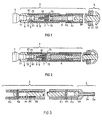
- zeigen ein bevorzugtes Ausführungsbeispiel eines auf einen Brennstab aufgesetzten Adapters im geschlossenen bzw. geöffneten Zustand, wobei das Handhabungsteil einen Griff zum Manipulieren des Adapters enthält.
- FIG 3
- zeigt das obere Ende eines Adapters mit einem Handhabungsteil, das wie die Endkappe eines Siedewasser-Brennstabs ausgebildet ist.
- 1 and 2
- show a preferred embodiment of an adapter placed on a fuel rod in the closed or open state, wherein the handling part contains a handle for manipulating the adapter.
- FIG 3
- shows the upper end of an adapter with a handling part, which is designed like the end cap of a boiling water fuel rod.
In Figur 1 ist die Endkappe eines Brennstabs 1 erkennbar, die
ein verjüngtes Ende 11 besitzt, in das seitlich eine Ringnut
12 als Profil eingearbeitet ist. Dieses verjüngte Ende 11 des
Brennstabs 1 ist in axialer Richtung bis zum Anschlag in das
vordere Ende 6 eines Adapters eingeführt, der im wesentlichen
aus dem stabförmigen Teil 2 besteht. Der stabförmige Teil 2
ist nur geringfügig dünner als der Brennstab 1, der dadurch
auf die Länge eines normalen Brennstabs verlängert wird. Der
verkürzte Brennstab und das stabförmige Teil kann also wie
ein Brennstab normaler Länge gehandhabt werden, neben den er
auf die übliche Weise durch die Maschen der Abstandhalter
hindurch in das Brennelement eingesetzt werden soll.The end cap of a
Hierzu wird der den Brennstab tragende Adapter an einem Handhabungsteil
3 an seinem anderen Ende ergriffen. Der entsprechende
Griff 33 bildet das Ende einer Betätigungsstange 34,
die in einer Muffe 32 gelagert ist und im Inneren des stabförmigen
Teils 2 zu einem in axialer Richtung beweglichen Betätigungsglied
4 führt. Die Muffe 32 ist durch eine Steckverbindung
oder auf andere Weise an einem Flansch 31 gehalten,
der an das Ende des stabförmigen Teils 2 angeformt ist.
Flansch 31 und Muffe 32 bilden also eine lösbare Kupplung und
wenn z.B. die Muffe 32 mit dem Griff 33 abgenommen ist, kann
der Adapter nicht mehr vom Brennstab gelöst werden. Ein unbeabsichtigtes
Lösen des Brennstabs ist dann nicht möglich.For this purpose, the adapter carrying the fuel rod is attached to a handling
In Figur 3 ist das Handhabungsteil am hinteren Ende des Adapters
als ein hohler Zapfen ausgebildet, der die gleiche Außenkontur
besitzt wie die Endstopfen der Brennstäbe normaler
Länge, die in diesem Brennelement eingesetzt sind. In einem
solchen Fall kann ein verkürzter Brennstab mit angesetztem
Adapter wie ein gewöhnlicher Brennstab von einer Brennstab-Wechselmaschine
gehandhabt werden. Auch in diesem Fall wird
das erwähnte Betätigungsglied 4 durch die im stabförmigen
Teil 2 axial beweglich gelagerte Betätigungsstange 34 betätigt,
die in diesem Fall ganz im Inneren des Adapters angeordnet
ist. Um die Betätigungsstange zu verschieben, weist
der hohle Zapfen 35 eine Zugangsöffnung 36 für ein Stangenwerkzeug
auf.In Figure 3, the handling part is at the rear end of the adapter
formed as a hollow spigot that has the same outer contour
has like the end plugs of the fuel rods more normal
Length used in this fuel assembly. In one
in such a case, a shortened fuel rod with attached
Adapter like an ordinary fuel rod from a fuel rod changing machine
be handled. In this case too
the mentioned
Vom Vorderende des Adapters bis zum Handhabungsteil erstreckt
sich ein Außenrohr, das aus mehreren, miteinander verschraubten
Rohrstücken 5, 51, 52 zusammengesetzt sein kann. Figur 3
zeigt, daß die Betätigungsstange 34, die mit ihrem einen Ende
im Handhabungsteil 3 gelagert ist, in diesem Außenrohr geführt
ist, wozu die Längsschlitze 53, 54 vorgesehen sind, in
die entsprechende, am Außenrohr befestigte Führungsbolzen 55,
56 eingreifen. Dabei hält eine Rückstellfeder 57, die an einem
an der Betätigungsstange 34 angeordneten Anschlag 58 angreift,
die Betätigungsstange 34 in einer Ruhestellung, in
der die Betätigungsstange 34 nicht am Betätigungsglied 4 anschlägt.
Das Betätigungsglied 4 kann also nur entgegen der
Kraft dieser Rückstellfeder 57 aus ihrer Ruhestellung heraus
nach vorne geschoben werden.Extends from the front end of the adapter to the handling part
an outer tube consisting of several, screwed together
Die Ruhestellung entspricht nach Figur 1 dem Zustand, in dem
eine Schließzange 7 im Vorderende 6 des Adapters in das Profil
12 am verjüngten Ende des Brennstabs formschlüssig eingreift.
Zwischen einem Anschlag 9 im Vorderende des Adapters
und dieser Schließzange 7 ist eine weitere Rückstellfeder 10
eingespannt, die die Schließzange in der Ruhestellung hält.According to FIG. 1, the rest position corresponds to the state in which
a
Diese Schließzange 7 ist wie eine Hülse ausgebildet, die in
einem entsprechenden Ringraum 61 des Vorderendes 6 und im Inneren
des an das Vorderende anschließenden Rohrstücks 5 gelagert
ist und entgegen der Kraft der Rückstellfeder 10 zum
Vorderende hin in axialer Richtung beweglich ist. Die Hülse 7
(Schließzange) besteht in diesem Fall aus einem Basiskörper
71 und den beiden, das eingeführte, verjüngte Brennstab-Ende
11 seitlich umschließenden Schließbacken 72.This locking
In der geschlossenen Stellung (Figur 1) der Schließzange
drücken diese Schließbacken 72 beweglich im Außenrohr 5 gelagerte
Schließglieder 8 in das Profil 12 des verjüngten Brennstab-Endes.In the closed position (Figure 1) of the locking pliers
press these locking
Diese Schließglieder 8 sind in diesem Fall zylindrisch ausgebildet
und seitlich in entsprechenden Ausnehmungen 91 des Außenrohrs
5 geführt. Sie sind daher senkrecht zur Längsachse
des Adapters beweglich, sobald ein entsprechender, in die
Schließbacken 72 eingearbeiteter Ausweichraum 73, der zur
Längsachse des Adapters hin offen ist, zugänglich wird. Dies
geschieht, wenn die Schließzange 7 bzw. die Schließbacken 72
in die geöffnete Stellung geschoben werden, wie in Figur 2
gezeigt ist.In this case, these closing
In dieser Stellung der Schließbacken 72 bzw. der Hülse 7
(Schließzange) sind dann die Schließglieder 8 beweglich und
geben das eingeführte Ende des Brennstabs mit dem Profil 12
frei, sobald der Adapter vom Brennstab abgehoben wird.In this position, the closing
In Figur 1 ist nicht erkennbar, daß das verjüngte Ende 11 des
Brennstabs nicht vollkommen rotationssymmetrisch bezüglich
der Brennstab-Längsachse ist, sondern auf der Seite, die dem
Betrachter der Figur 1 abgewandt ist, eine ebene Angriffsfläche
aufweist. Auch die entsprechende Öffnung, durch die das
verjüngte Ende des Brennstabs in das Vorderende 6 des stabförmigen
Teils 2 eingeführt wird, weist einen entsprechenden
Querschnitt auf, also eine an der Angriffsfläche, ebene Anschlagfläche.
Bezüglich einer Drehung um die Längsachse ist
also das verjüngte Brennstab-Ende 11 formschlüssig mit dem
Vorderende 6 des stabförmigen Teils 2 verbunden und kann
durch Drehung des Adapters gedreht werden. In der Schließstellung
ist daher der Adapter nicht nur über die in das Profil
12 eingreifenden Schließglieder 8 formschlüssig verbunden,
sondern auch über die erwähnten, ebenen Flächen auch gegenüber
einer relativen Drehbewegung von Stab und Adapter gesichert.
Solange auf das Betätigungsglied 4 und Betätigungsstange
34 keine äußeren Kräfte einwirken, sitzt daher der Adapter
fest auf dem Brennstab und durch eine schraubenförmige
Bewegung des Adapters kann der Brennstab auch mit einem an
seinem anderen Ende sitzenden Gewinde z.B. in eine Bodenplatte
des Brennelements eingeschraubt oder ausgeschraubt
werden.In Figure 1 it can not be seen that the
Claims (9)
- Adapter for a tapered end (11) of a nuclear reactor fuel rod (1), which end carries a side profile (12), having a rod-shaped part (2) and a handling part (3) at the rear end of the rod-shaped part, it being possible to actuate a clamping chuck (7) in a front end of the rod-shaped part (2) from an opening in the handling part (3) in such a way that, in an open position; it permits the tapered end (11) of the fuel rod (1) to be introduced in the axial direction into the front end (6) of the rod-shaped part (2) and into the clamping chuck (7) and, in a closed position, engages positively in the profile (12) of the introduced end (11) of the fuel rod, and the rod-shaped part (2), furthermore, lengthening the fuel rod in the axial direction beyond the introduced end of the fuel rod without protruding laterally beyond the cross section of the fuel rod (1), and an actuation element (4) being movably guided linearly in the axial direction in the rod-shaped part (2), by means of which actuation element (4) the clamping chuck (7) is optionally brought into the open and closed position.
- Adapter according to Claim 1, characterized in that a bar (34), which leads to the actuation element (4), is displaceably supported in the handling part (3).
- Adapter according to Claim 1 or 2, characterized in that, in the open position, the clamping chuck (7) is offset in the axial direction relative to the closed position.
- Adapter according to Claim 3, characterized in that the clamping chuck (7) is held in the closed position by a return spring (10) and can be displaced into the open position against the force of this return spring (10).
- Adapter according to one of Claims 1 to 4, characterized in that the clamping chuck (7) carries clamping elements (8) which, in the closed position, engage in the profile (12) and, in the open position, can be moved laterally relative to the longitudinal axis of the rod-shaped part.
- Adapter according to one of Claims 1 to 5, characterized in that the clamping chuck (7) has two clamping jaws (72) which, by displacement, are optionally brought into the open position or the closed position, it being possible to introduce the tapered end of the fuel rod between the clamping jaws and each clamping jaw (72) carrying a clamping element (8) which, in the open position, can be moved in a recess (91) of the clamping jaw open towards the longitudinal axis of the rod-shaped part and, in the closed position, is pressed into the profile (12).
- Adapter according to one of Claims 1 to 6, characterized in that the clamping chuck (7) is held in the closed position by at least one spring (10) and is brought into the open position against the force of the spring.
- Adapter according to one of Claims 1 to 7, characterized in that an outer tube (5, 51, 52) of the handling part (3) leads as far as the front end (6) of the rod-shaped part (2), which has an opening corresponding to the cross section of the tapered end (11) of the fuel rod (1) and in which the clamping chuck (7) and an actuation element (4) with an actuating bar (34) are movably supported and guided in the axial direction.
- Method of inserting or removing fuel rods in a nuclear reactor fuel element which contains fuel rods of different lengths, the tapered end of a shorter fuel rod being introduced into an adapter, according to one of Claims 1 to 8, in the open position of the clamping chuck (7) of the adapter, the clamping chuck being brought into the closed position and the adapter being grasped at the handling part.
Applications Claiming Priority (2)
| Application Number | Priority Date | Filing Date | Title |
|---|---|---|---|
| DE19751688 | 1997-11-21 | ||
| DE19751688A DE19751688C1 (en) | 1997-11-21 | 1997-11-21 | Adapter for a shortened fuel rod of a nuclear reactor fuel assembly and method for inserting or removing fuel rods |
Publications (2)
| Publication Number | Publication Date |
|---|---|
| EP0918337A1 EP0918337A1 (en) | 1999-05-26 |
| EP0918337B1 true EP0918337B1 (en) | 2002-08-07 |
Family
ID=7849463
Family Applications (1)
| Application Number | Title | Priority Date | Filing Date |
|---|---|---|---|
| EP98121289A Expired - Lifetime EP0918337B1 (en) | 1997-11-21 | 1998-11-09 | Adapter for a partial-length fuel rod of a nuclear reactor fuel assembly |
Country Status (3)
| Country | Link |
|---|---|
| EP (1) | EP0918337B1 (en) |
| DE (2) | DE19751688C1 (en) |
| ES (1) | ES2180108T3 (en) |
Families Citing this family (1)
| Publication number | Priority date | Publication date | Assignee | Title |
|---|---|---|---|---|
| US11348700B2 (en) | 2019-05-15 | 2022-05-31 | Ge-Hitachi Nuclear Energy Americas Llc | Boiling water reactor blade guide and exchange tool |
Family Cites Families (10)
| Publication number | Priority date | Publication date | Assignee | Title |
|---|---|---|---|---|
| US3990591A (en) * | 1975-01-31 | 1976-11-09 | Stearns-Roger Corporation | Multiple function nuclear handling apparatus |
| FR2460027A1 (en) * | 1979-06-26 | 1981-01-16 | Framatome Sa | PROCESS FOR HANDLING COMBUSTIBLE ASSEMBLIES AND PENS WHEN RECHARGING A NUCLEAR REACTOR |
| US4539174A (en) * | 1982-09-29 | 1985-09-03 | Maine Yankee Atomic Power Company | Fuel pin transfer tool |
| FR2536201B1 (en) * | 1982-11-16 | 1985-07-19 | Fragema Framatome & Cogema | INSTALLATION FOR THE REPAIR OF NUCLEAR FUEL ASSEMBLIES |
| US5112570A (en) * | 1988-04-04 | 1992-05-12 | Hewlett-Packard Company | Two-phase pressure drop reduction bwr assembly design |
| JP2521004B2 (en) * | 1991-05-17 | 1996-07-31 | ゼネラル・エレクトリック・カンパニイ | Upper plug for partial length fuel rods and a gripping mechanism therefor |
| DE9210304U1 (en) * | 1992-07-31 | 1992-10-29 | Siemens Ag, 8000 Muenchen, De | |
| US5329563A (en) * | 1993-07-29 | 1994-07-12 | Combustion Engineering Inc. | Control rod latch tool |
| TW294813B (en) * | 1994-11-23 | 1997-01-01 | Gen Electric | |
| US5825837A (en) * | 1996-03-11 | 1998-10-20 | General Electric Company | Extraction tool for partial length fuel rods in nuclear fuel assemblies |
-
1997
- 1997-11-21 DE DE19751688A patent/DE19751688C1/en not_active Expired - Fee Related
-
1998
- 1998-11-09 ES ES98121289T patent/ES2180108T3/en not_active Expired - Lifetime
- 1998-11-09 EP EP98121289A patent/EP0918337B1/en not_active Expired - Lifetime
- 1998-11-09 DE DE59805087T patent/DE59805087D1/en not_active Expired - Lifetime
Also Published As
| Publication number | Publication date |
|---|---|
| EP0918337A1 (en) | 1999-05-26 |
| DE59805087D1 (en) | 2002-09-12 |
| DE19751688C1 (en) | 1999-08-19 |
| ES2180108T3 (en) | 2003-02-01 |
Similar Documents
| Publication | Publication Date | Title |
|---|---|---|
| EP0531897B1 (en) | Press tool for crimping a cylindrical pressed article or a pressed article having a cylindrical cross section on a round profile in particular a pipe conduit | |
| EP0468335B1 (en) | Tool for crimping a connector to a conductor and an isolation | |
| DE10023675C2 (en) | mother | |
| DE2708292A1 (en) | PIPE CLAMP | |
| DE20017140U1 (en) | Device for manual collection of waste | |
| DE2357978A1 (en) | GRIPPING DEVICE FOR CONTROL RODS IN NUCLEAR REACTORS | |
| DE1628014A1 (en) | Gripping tool | |
| EP3180138B1 (en) | Bending tool and gripping device for manipulating the bending tool | |
| DE3523828C1 (en) | Bending device for the production of molded parts consisting of wire or strip sections | |
| EP3499055A1 (en) | Asymmetrical locking bolt with different rotating positions | |
| DE3033349A1 (en) | ALIGNMENT TOOL FOR SPACERS FROM CORE REACTOR FUEL ELEMENTS | |
| EP0918337B1 (en) | Adapter for a partial-length fuel rod of a nuclear reactor fuel assembly | |
| EP0630313B1 (en) | Manipulator | |
| DE3228380A1 (en) | Nuclear reactor fuel element | |
| DE202021101479U1 (en) | screwdriver | |
| DE19955289C2 (en) | Jack puller | |
| DE2359163A1 (en) | GRIPPING DEVICE FOR LONG STRETCHED BODIES THAT ARE TO BE INSERTED INTO RECEPTION OPENINGS AND TO BE PULLED OUT OF THESE, IN PARTICULAR FOR FUEL ELEMENTS AND CONTROL RODS IN A CORE REACTOR | |
| DE3100854C2 (en) | ||
| DE2915339C2 (en) | Quick-release fastener for attaching operating handles to a spray rack | |
| DE211595C (en) | ||
| EP0544030A1 (en) | Vacuum gate valve | |
| DE1627418A1 (en) | Tool for deforming sleeves on fastening elements | |
| DE1615800C (en) | Tool for stripping off a cable jacket | |
| AT372884B (en) | DEVICE FOR PUNCHING HOLES IN GUTTERS | |
| DE4125945A1 (en) | CORE REACTOR FUEL ELEMENT |
Legal Events
| Date | Code | Title | Description |
|---|---|---|---|
| PUAI | Public reference made under article 153(3) epc to a published international application that has entered the european phase |
Free format text: ORIGINAL CODE: 0009012 |
|
| AK | Designated contracting states |
Kind code of ref document: A1 Designated state(s): DE ES FI SE |
|
| AX | Request for extension of the european patent |
Free format text: AL;LT;LV;MK;RO;SI |
|
| 17P | Request for examination filed |
Effective date: 19990706 |
|
| AKX | Designation fees paid |
Free format text: DE ES FI SE |
|
| RAP1 | Party data changed (applicant data changed or rights of an application transferred) |
Owner name: FRAMATOME ANP GMBH |
|
| RTI1 | Title (correction) |
Free format text: ADAPTER FOR A PARTIAL-LENGTH FUEL ROD OF A NUCLEAR REACTOR FUEL ASSEMBLY |
|
| GRAG | Despatch of communication of intention to grant |
Free format text: ORIGINAL CODE: EPIDOS AGRA |
|
| 17Q | First examination report despatched |
Effective date: 20020314 |
|
| GRAG | Despatch of communication of intention to grant |
Free format text: ORIGINAL CODE: EPIDOS AGRA |
|
| GRAH | Despatch of communication of intention to grant a patent |
Free format text: ORIGINAL CODE: EPIDOS IGRA |
|
| GRAH | Despatch of communication of intention to grant a patent |
Free format text: ORIGINAL CODE: EPIDOS IGRA |
|
| GRAA | (expected) grant |
Free format text: ORIGINAL CODE: 0009210 |
|
| AK | Designated contracting states |
Kind code of ref document: B1 Designated state(s): DE ES FI SE |
|
| REF | Corresponds to: |
Ref document number: 59805087 Country of ref document: DE Date of ref document: 20020912 |
|
| REG | Reference to a national code |
Ref country code: ES Ref legal event code: FG2A Ref document number: 2180108 Country of ref document: ES Kind code of ref document: T3 |
|
| PLBE | No opposition filed within time limit |
Free format text: ORIGINAL CODE: 0009261 |
|
| STAA | Information on the status of an ep patent application or granted ep patent |
Free format text: STATUS: NO OPPOSITION FILED WITHIN TIME LIMIT |
|
| 26N | No opposition filed |
Effective date: 20030508 |
|
| REG | Reference to a national code |
Ref country code: DE Ref legal event code: R082 Ref document number: 59805087 Country of ref document: DE Representative=s name: MOERTEL, ALFRED, DIPL.-PHYS. DR.RER.NAT., DE |
|
| REG | Reference to a national code |
Ref country code: DE Ref legal event code: R082 Ref document number: 59805087 Country of ref document: DE Representative=s name: MEISSNER BOLTE PATENTANWAELTE RECHTSANWAELTE P, DE Effective date: 20131112 Ref country code: DE Ref legal event code: R082 Ref document number: 59805087 Country of ref document: DE Representative=s name: MEISSNER BOLTE & PARTNER GBR, DE Effective date: 20131112 Ref country code: DE Ref legal event code: R082 Ref document number: 59805087 Country of ref document: DE Representative=s name: MOERTEL, ALFRED, DIPL.-PHYS. DR.RER.NAT., DE Effective date: 20131112 Ref country code: DE Ref legal event code: R081 Ref document number: 59805087 Country of ref document: DE Owner name: AREVA GMBH, DE Free format text: FORMER OWNER: AREVA NP GMBH, 91052 ERLANGEN, DE Effective date: 20131112 |
|
| REG | Reference to a national code |
Ref country code: DE Ref legal event code: R082 Ref document number: 59805087 Country of ref document: DE Representative=s name: MEISSNER BOLTE PATENTANWAELTE RECHTSANWAELTE P, DE Ref country code: DE Ref legal event code: R082 Ref document number: 59805087 Country of ref document: DE Representative=s name: MEISSNER BOLTE & PARTNER GBR, DE |
|
| REG | Reference to a national code |
Ref country code: DE Ref legal event code: R082 Ref document number: 59805087 Country of ref document: DE Representative=s name: MEISSNER BOLTE PATENTANWAELTE RECHTSANWAELTE P, DE |
|
| PGFP | Annual fee paid to national office [announced via postgrant information from national office to epo] |
Ref country code: DE Payment date: 20161125 Year of fee payment: 19 Ref country code: FI Payment date: 20161123 Year of fee payment: 19 |
|
| PGFP | Annual fee paid to national office [announced via postgrant information from national office to epo] |
Ref country code: SE Payment date: 20161124 Year of fee payment: 19 Ref country code: ES Payment date: 20161124 Year of fee payment: 19 |
|
| REG | Reference to a national code |
Ref country code: DE Ref legal event code: R119 Ref document number: 59805087 Country of ref document: DE |
|
| REG | Reference to a national code |
Ref country code: SE Ref legal event code: EUG |
|
| PG25 | Lapsed in a contracting state [announced via postgrant information from national office to epo] |
Ref country code: FI Free format text: LAPSE BECAUSE OF NON-PAYMENT OF DUE FEES Effective date: 20171109 |
|
| PG25 | Lapsed in a contracting state [announced via postgrant information from national office to epo] |
Ref country code: SE Free format text: LAPSE BECAUSE OF NON-PAYMENT OF DUE FEES Effective date: 20171110 |
|
| PG25 | Lapsed in a contracting state [announced via postgrant information from national office to epo] |
Ref country code: DE Free format text: LAPSE BECAUSE OF NON-PAYMENT OF DUE FEES Effective date: 20180602 |
|
| REG | Reference to a national code |
Ref country code: ES Ref legal event code: FD2A Effective date: 20181226 |
|
| PG25 | Lapsed in a contracting state [announced via postgrant information from national office to epo] |
Ref country code: ES Free format text: LAPSE BECAUSE OF NON-PAYMENT OF DUE FEES Effective date: 20171110 |