EP0917959A2 - Recording medium cassette - Google Patents
Recording medium cassette Download PDFInfo
- Publication number
- EP0917959A2 EP0917959A2 EP98121984A EP98121984A EP0917959A2 EP 0917959 A2 EP0917959 A2 EP 0917959A2 EP 98121984 A EP98121984 A EP 98121984A EP 98121984 A EP98121984 A EP 98121984A EP 0917959 A2 EP0917959 A2 EP 0917959A2
- Authority
- EP
- European Patent Office
- Prior art keywords
- recording
- tape
- recording medium
- carriage
- head
- Prior art date
- Legal status (The legal status is an assumption and is not a legal conclusion. Google has not performed a legal analysis and makes no representation as to the accuracy of the status listed.)
- Withdrawn
Links
Images


Classifications
-
- B—PERFORMING OPERATIONS; TRANSPORTING
- B41—PRINTING; LINING MACHINES; TYPEWRITERS; STAMPS
- B41J—TYPEWRITERS; SELECTIVE PRINTING MECHANISMS, i.e. MECHANISMS PRINTING OTHERWISE THAN FROM A FORME; CORRECTION OF TYPOGRAPHICAL ERRORS
- B41J15/00—Devices or arrangements of selective printing mechanisms, e.g. ink-jet printers or thermal printers, specially adapted for supporting or handling copy material in continuous form, e.g. webs
- B41J15/04—Supporting, feeding, or guiding devices; Mountings for web rolls or spindles
- B41J15/044—Cassettes or cartridges containing continuous copy material, tape, for setting into printing devices
-
- B—PERFORMING OPERATIONS; TRANSPORTING
- B41—PRINTING; LINING MACHINES; TYPEWRITERS; STAMPS
- B41J—TYPEWRITERS; SELECTIVE PRINTING MECHANISMS, i.e. MECHANISMS PRINTING OTHERWISE THAN FROM A FORME; CORRECTION OF TYPOGRAPHICAL ERRORS
- B41J3/00—Typewriters or selective printing or marking mechanisms characterised by the purpose for which they are constructed
- B41J3/407—Typewriters or selective printing or marking mechanisms characterised by the purpose for which they are constructed for marking on special material
-
- B—PERFORMING OPERATIONS; TRANSPORTING
- B41—PRINTING; LINING MACHINES; TYPEWRITERS; STAMPS
- B41J—TYPEWRITERS; SELECTIVE PRINTING MECHANISMS, i.e. MECHANISMS PRINTING OTHERWISE THAN FROM A FORME; CORRECTION OF TYPOGRAPHICAL ERRORS
- B41J35/00—Other apparatus or arrangements associated with, or incorporated in, ink-ribbon mechanisms
- B41J35/28—Detachable carriers or holders for ink-ribbon mechanisms
Definitions
- the present invention relates to a recording medium cassette used in a recording apparatus which records characters, marks, etc. on a recording medium, and more particularly to a recording medium cassette used in a recording apparatus that has respective advantages of a line recording mode for performing recording with a recording head fixedly supported with respect to the recording medium and a serial recording mode for performing recording with a recording head allowed to scan a recording medium.
- thermal printer wherein a thermal recording head melts ink applied on an ink ribbon so that the melted ink adheres to a recording medium.
- This thermal printer can record characters in a single or multiple color(s) on the recording medium by operating the recording head through a single-color ink ribbon or a full-color ink ribbon provided thereon with ink regions, each of which has a fixed length, that are arranged in order so that adjacent ink regions have different colors.
- a recording mode of the thermal printer there are a line recording mode and a serial recording mode.
- a recording head provided with recording elements arranged corresponding to the width in a main scanning direction of a recording medium.
- the printer performs printing on the recording medium that is fed in a sub-scanning direction perpendicular to the direction of arrangement of the recording elements.
- a recording head provided with recording elements arranged corresponding to the predetermined length in a sub-scanning direction of a recording medium.
- the printer While moving this recording head in a main scanning direction, the printer performs printing of a line on the recording medium fixedly supported and, after the one-line printing, feeds the recording medium in the sub-scanning direction. Then, the recording head is caused to reciprocate again in the main scanning direction to perform recording.
- the thermal printer is a color thermal printer that uses a multi-color ink ribbon having color inks of magenta, cyan, and yellow arranged in order and carries out recording operation by superimposing the inks of different colors at the same position to blend into one another, such the printer has the following advantages and disadvantages.
- Advantages of the color thermal printer using the serial recording mode are that : (1) there is no limitation on the size of a recording head, in particular, in the main scanning direction, whereby a small-sized recording head can be made so that the manufacturing cost thereof is reduced; (2) the printer performs recording while moving the recording head with respect to the recording medium fixedly supported, achieving high precision of superimposition of inks and reducing misalignment of the inks on the recording medium; and (3) a recording head can make recording on the recording medium which is relatively long in the sub-scanning direction if the recording medium is fed in the sub-scanning direction after the one-line printing and then the recording head is moved back and forth in the main scanning direction.
- advantages of the color thermal printer using the line recording mode are that; (1) the printer can perform simultaneous recording in the main scanning direction, so that the recording speed is high and a period of time needed for recording is short; and (2) the ratio of the used regions of the ink ribbon to the actually recorded area on the recording medium is large, so that the recording efficiency is high and the running cost is reduced.
- Disadvantages are that; (1) since the printer feeds the recording medium in the sub-scanning direction while fixedly supporting the recording head, the recording medium must repeatedly be fed back and forth in the sub-scanning direction whenever the color of the ink ribbon is changed and there is a case that the recording medium is fed out of the printer in view of a feeding route in the printer, when a user may possibly touch the recording medium fed out of the printer, which causes displacement of recorded positions; (2) it is difficult to stop movement of the recording medium at a predetermined position when the recording medium is fed back and forth plural times in the sub-scanning direction to superimpose inks at the same position on the recording medium, so that the recording positional precision is so low that color displacement often occurs; and (3) if the recording medium is a roll of paper extending in a longitudinal direction, a special-purpose feeding device is required to rewind the roll of paper according to the change of diameter of the rolled paper and therefore color recording is generally difficult to perform on the continuous roll of paper.
- the present invention has been made in consideration of the above advantages and disadvantages and to provide a recording medium cassette used in a recording apparatus capable of performing recording on a recording medium regardless of the length thereof, and of achieving high speed recording, providing high recording positional precision, and reducing the running cost of an ink ribbon.
- a recording medium cassette used in a recording apparatus including a recording head for recording characters and others on a recording medium, the head being provided with a plurality of recording elements arranged in a first direction, a carriage mounting the recording head thereon, a first feeding device for moving the carriage in a second direction perpendicular to the first direction, a second feeding device for feeding the recording medium in the second direction and stopping the recording medium, the recording apparatus performing recording characters and others on the recording medium through the recording head while reciprocating the carriage by the first feeding device in the second direction, when feeding of the recording medium is stopped through the second feeding device, the recording medium cassette including an exposure part for exposing a part of the recording medium to allow the recording head to press against the recording medium within a predetermined recording area defined on the recording medium while the carriage is reciprocated through the first feeding device, and a holding member for holding the recording medium exposed through the exposure part.
- the recording apparatus in which the recording medium cassette is mounted according to the present invention, while the carriage is reciprocated in the second direction perpendicular to the first direction, i.e., the arrangement direction of the recording elements within a recording area on the recording medium supported at rest, the recording elements arranged in a line corresponding to the width of the recording medium in the first scanning direction perform recording on the fixed recording medium.
- the recording apparatus can execute high-speed recording on the recording medium as fast as the case of the line recording operation.
- the carriage mounting the recording head is moved in the second direction with respect to the fixed recording medium, it can perform movement at high precision as compared with the case where the recording medium is fed in the second direction with respect to the fixed recording head, so that an excellent recording quality can be provided.
- the recording medium cassette can be removably mounted in the recording apparatus so that the recording medium is held within the range where the carriage is reciprocated. Accordingly, after all recording medium accommodated in the cassette has been used, this used cassette can be exchanged for a new one accommodating an unused recording medium, whereby to use the recording apparatus again.
- a tape cassette used in a tape recording apparatus including a thermal head for recording characters and others on a long recording tape through an ink ribbon, the head being provided with a plurality of heating elements arranged in a first direction, a carriage mounting the thermal head thereon, a first feeding device for moving the carriage in a second direction perpendicular to the first direction, a second feeding device for feeding the recording tape in the second direction and stopping the recording tape, the tape recording apparatus performing recording characters and others on the recording tape through the thermal head while reciprocating the carriage by the first feeding device in the second direction, when feeding of the recording tape is stopped through the second feeding device, the recording tape cassette including a tape holding part for holding the recording tape in a rolled state, a tape discharge part for discharging the recording tape drawn out from the tape holding part, a pair of tape guide parts formed connecting the tape holding part and the tape discharge part and disposed opposite to and away from each other, an open part defined by the tape holding part, the tape discharge part, and the tape guide parts
- the recording apparatus in this embodiment is applied to a tape printing apparatus for printing many images of characters or marks on a recording medium such as a tape, a thermal printer for printing the images on recording paper through an ink ribbon.
- Fig. 1 is a perspective view of an embodiment of a tape printing apparatus embodying the recording apparatus according to the present invention, a part of which is broken to show more clearly the inside components of the apparatus.
- Fig. 2 is plane view of a roller holder and others used in the tape printing apparatus.
- Fig. 3 is a schematic front view of an ink ribbon that is drawn from a ribbon cassette used in the tape printing apparatus.
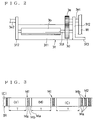
- Fig. 4 is a perspective view of a tape cassette used in the tape printing apparatus.
- Fig. 5 is a cross sectional view of the tape cassette along the line A-A of Fig. 1.
- the tape printing apparatus has a box-like body 1 provided with a left side wall 1L, a right side wall 1R, a front side wall 1M, and a rear side wall 1N. Those side walls 1L, 1R, 1M, and 1N are jointed with a top wall (not shown) and a bottom wall, thereby constituting the body 1.
- a carriage CA which mounts a thermal head HD
- a carriage moving system 2 for moving the carriage CA
- a tape feeding system 3 for feeding a tape TP which is a recording medium
- a platen 4 arranged opposite to the thermal head through the tape TP
- a tape cutting unit 5 for cutting the tape TP
- a ribbon feeding system 7 for feeding an ink ribbon IR with respect to the thermal head HD.
- the carriage moving system 2 is provided with a stepping motor attached to the side wall 1L from the outside thereof, a motor gear 2a mounted on a motor shaft SM1 penetrating the side wall 1L toward the inside of the box-like body 1, a drive pulley 2b meshing with the motor gear 2a, a timing belt supporting gear 2c formed integrally with the drive pulley 2b, an idle pulley 2d mounted on a shaft J1 fixed on the side wall 1L and extended toward the side wall 1R, a timing belt 2e wound on the gear 2c and the idle pulley 2d and combined with the carriage CA, and carriage guide bars CA2 inserted in holes CA1 (two holes in this embodiment) formed in the carriage CA, extending along the side walls 1L and 1R, i.e., in the direction indicated by an arrow Y1 in Fig. 1.
- the drive pulley 2b and the timing belt supporting gear 2c are moved round counterclockwise (or clockwise), so that the timing belt 2e is moved round in the opposite direction to the direction Y1 (or in the direction Y1).
- the carriage CA is thus caused to move back and force along the carriage guide bars CA2 in accordance with the rotating direction of the motor shaft SM1 of the stepping motor SM.
- the moving system 2 moves the carriage CA mounting thereon a thermal head HD in the sub-scanning direction perpendicular to the direction of arrangement of heating elements provided on the thermal head HD.
- the carriage CA is provided with a target CA4 for detecting the position of the carriage CA along the direction Y1.
- This target CA4 is arranged so as to pass the detection range of a carriage origin point detecting sensor CA5 disposed in a predetermined position inside of the side wall 1L.
- the tape printing apparatus in the present embodiment can detect that the carriage CA has passed the origin point.
- the tape feeding system 3 is provided with a tape feed roller 3a and a tape drive roller 3b disposed below the roller 3a for feeding tape TP in the sub-scanning direction (i.e., in the opposite direction to the direction Y1), both rollers extending along the direction indicated by an arrow Z1 perpendicular to the direction Y1, a stepping motor SN attached to the side wall 1R to rotate the tape drive roller 3b, a motor gear 3c mounted on a motor shaft SN1 penetrating the side wall 1R toward the inside of the box-like body 1, a tape drive gear 3d (see Fig. 2) mounted on a roller shaft 3b1, on the side wall 1R side, that rotates integrally with the tape drive roller 3b, and a transmission gear 3e disposed between the tape drive gear 3d and the motor gear 3c and engaged with them respectively.
- the tape drive roller 3b When the stepping motor SN is driven to rotate the motor shaft SN1 and the motor gear 3c counterclockwise in Fig. 1, the transmission gear 3e engaging with the motor gear 3c is rotated clockwise, causing the tape drive gear 3d to rotate counterclockwise and the tape drive roller 3b counterclockwise in Fig. 1. If the tape drive roller 3b is made contact under pressure with the tape feed roller 3a, the tape drive roller 3b rotating counterclockwise in Fig. 1 feeds the tape TP in the sub-scanning direction (i.e., in the opposite direction to the direction Y1) in cooperation with the tape feed roller 3a. In this way, the tape feeding system 3 feeds the tape TP which is a recording medium in the sub-scanning direction.
- the tape drive roller 3b is held in a roller holder 3f disposed inside of the side walls 1R and 1L for the purpose of moving the tape drive roller 3b away from the tape feed roller 3a to make it easy to insert the tape TP between the both rollers 3a and 3b.
- the roller holder 3f has a bottom plate 3f1 extending in a longitudinal direction of the tape drive roller 3b and bent portions 3f2 extending upward from both ends of the bottom plate 3f1, forming each of the bent portions 3f2 forming an L-shaped cross section.
- the roller shaft 3b1 is supported rotatably on those bent portions 3f2.
- a support shaft 3e1 of the transmission gear 3e penetrates one of the bent portions 3f2 (right one in Fig. 2) to support it so that the tape drive gear 3d is rotated as a planet gear around the transmission gear 3e while always engaging with it.
- a support shaft 3e2 provided extending from the side wall 1L side and positioned coaxially with the rotating center of the support shaft 3e1 supports the other bent portion 3f2.
- the tape drive roller 3b thus can be made to come into uniform contact under pressure with or move away from the tape feed roller 3a.
- An operational plate 3f3 is formed extending from the right bent portion 3f2 toward the outside of the side wall 1R.
- a cam 3h that rotates with an operating lever 3g extending toward the side wall 1M is provided so as to be in contact with the operational plate 3f3.
- a plurality of compressive coil springs 3k are disposed under the roller holder 3f. The biasing force of the coil springs 3k can cause the tape drive roller 3b to come into pressure-contact with the tape feed roller 3a.
- the roller holder 3f is rotated about the support shaft 3e1 of the transmission gear 3e. Also in the case that the tape drive roller 3b is transferred from a released state with respect to the tape feed roller 3a to a pressure-contact state with the same, the tape drive roller 3b can feed the tape TP inserted between the tape drive roller 3b and the tape feed roller 3a in the sub-scanning direction (opposite to the direction Y1) upon reception of the driving force of the stepping motor SN.
- the thermal head HD is disposed on the carriage CA opposite to the platen 4 so that the thermal head HD extends from the carriage CA toward the side wall 1R. Heating elements that can generate heat per dot as recording elements are provided by the width corresponding to a line in the direction of an arrow Z1 on a recording surface of the thermal head HD.
- a ribbon detection sensor SE is disposed on the carriage CA on the side wall 1R side in substantially parallel to the thermal head HD. The ribbon detection sensor SE is arranged so that an ink ribbon IR is fed within the detection range of the sensor SE.
- the carriage CA is further provided with a motor CA3 for causing the thermal head HD, through a transmission mechanism (not shown) which transmits the driving force of the motor CA3 to the thermal head HD, to come into pressure-contact with the platen 4 with the tape TP put thereon or to move away from the platen 4.
- the color ribbon cassette RC having the length corresponding to the width of the heating elements arranged in a line is set on the carriage CA on the side wall 1R side without contact with the thermal head HD and the ribbon detection sensor SE.
- a plurality of positioning pins CA6 (two pins in the present embodiment) provided on the carriage CA on the side wall 1R side are fitted in positioning recesses (not shown) of the color ribbon cassette RC, setting the ribbon cassette RC on the carriage CA on the side wall 1R side.
- the ribbon feeding system 7 feeds the ink ribbon IR held in the color ribbon cassette RC in the opposite direction to the direction Y1.
- This ribbon feeding system 7 is provided with a spool 7a disposed downstream of the thermal head HD on the carriage CA and another spool 7b disposed upstream of the thermal head HD.
- the spool 7a is fitted to a reel RC1 for winding used ribbon in the ribbon cassette RC and the spool 7b is fitted to a reel RC2 for supplying unused ribbon.
- a ribbon winding mechanism (not shown) causes the spool 7a to rotate upon reception of the rotational driving force of the motor CA3, the reel RC1 allows the spool 7a to wind the ink ribbon IR that has been drawn out from the spool 7b and passed through the ribbon detection sensor SE and the recording surface side of the thermal head HD during recording operation.
- the mechanism using a single motor of causing the thermal head on the carriage to come into contact with or be released from the recording medium and of winding the ink ribbon on the carriage is well known in the art, for example, in Japanese patent application laid-open No. 62(1987)-94374 and other patent publications. The detailed explanation thereof is accordingly omitted herein.
- a tape cassette 8 for holding the tape TP on a rear side and the tape feed roller 3a on a front side can be set in the body 1 through an opening 1R1 formed in the side wall 1R.
- This tape cassette 8 holds the tape TP with its end part rolled around an axis 8a so that a forward end is drawn out in the sub-scanning direction from the rolled portion.
- the tape cassette 8 thus can hold long tape TP if having the back end part in a rolled state.
- the tape cassette 8 is provided with right and left guide portions 8b and 8c for supporting both ends in the direction Z1 of the tape TP and a front portion 8d which connects the guide portions 8b and 8c on the front side of the cassette 8 and holds therein the tape feed roller 3a.
- Those guide portions 8b and 8c prevent the forward end of the tape TP drawn out from the rolled portion from being caught in the space between components disposed in the body 1 when the tape cassette 8 is set moving from the side wall 1R side to the side wall 1L side in the body 1.
- the tape cassette 8 is formed with an opening 8e through which the thermal head HD is allowed to come into contact with the tape TP.
- the platen 4 is positioned extending in the sub-scanning direction within the opening 8e. In this state, the thermal head HD is moved in the range corresponding to the opening 8e.
- the tape guide portions 8b and 8c are formed with recesses 8b1 and 8c1 respectively, in which the both ends in the direction Z1 of the tape TP are inserted.
- two recesses (not shown) for positioning the tape cassette 8 are provided on the side wall 1L side of the tape cassette 8.
- Fig. 5 shows the positional relation between the tape guide portions 8b and 8c and the platen 4 and others.
- the tape guide portions 8b and 8c are displaced from the platen 4 and the moving range of the thermal head HD.
- the tape guide portion 8b disposed on the left side in Fig. 5 is placed at a position corresponding to the space between a lower surface of the thermal head HD and an upper surface 4a of the platen 4, while a lower surface 8b2 of the tape guide portion 8b is away from the upper surface 4a of the platen 4 at a slight distance (for example, 1-2 mm).
- the tape guide portion 8c on the opposite side does not come into contact with the platen 4 when the tape cassette 8 is set in the body 1, the tape guide portion 8c is designed to be thicker than the tape guide portion 8b in order to ensure the rigidity of the tape guide portion 8c made of plastic, for example.
- the thickness of the tape guide portion 8b is about 5mm, while that of the tape guide portion 8c is in the range of 7-10mm, so that a lower surface 8c2 of the tape guide portion 8c is positioned below the upper surface 4a of the platen 4 as shown in Fig. 5.
- the thermal head HD should be released from the platen 4 by the distance so that the tape guide portion 8c can pass through the space between the thermal head HD and the platen 4 at the time of setting of the tape cassette 8 in the body 1.
- the motor CA3 is therefore driven to move the thermal head HD sufficiently away from the platen 4.
- a cutting unit 5 for cutting a forward part of the tape TP is provided outside of the side wall 1M.
- This cutting unit 5 includes a fixed blade 5b, a movable blade 5a, and a lever connected to the movable blade 5a.
- a drive source 5d for example, an electromagnetic solenoid, etc.
- a blade moving lever 5c is caused to move the movable blade 5 up or down with respect to the fixed blade 5b, thereby to cut the part of the tape TP drawn out through a discharge port 1M1 formed in the side wall 1M.
- the cutting unit 5 is constructed as above for the purpose of cutting the recorded part of the tape TP by the length including a length x of a front margin provided ahead of the recording initial point of the recorded part of the tape TP or a length q of a rear margin provided following after the recording termination point of the recorded part, the length x or q having been optionally set with a keyboard IN and the like.
- a control unit CP (see Fig. 10) which will be mentioned later operates the drive source 5d to drive the lever 5c, thereby moving the movable blade 5a with respect to the fixed blade 5b.
- the lever 5c may be constructed to be operated by a user as the occasion demands.
- Fig. 6 is an explanatory view of showing the positional relation among the blades 5a and 5b and the rollers 3a and 3b, the relation between the blades 5a and 5b and the recording start position Pa, and a length P of the recording area.
- distance L is the distance between the recording start position Pa and a cut position K1 where the blades 5a and 5b cut the tape.
- the length P is a distance between the recording start position Pa and the recording end position Pb, in which the thermal head HD is allowed to move back and force in accordance with movement of the carriage CA.
- Fig. 7 simply shows the relation among the width W1 of the tape TP, the width W2 of a recordable range of the tape TP, the recording width W3 of the thermal head HD, and the width W4 of the platen 4.
- the length in a main scanning direction (a first direction) of the tape TP i.e., the tape width W1
- the recordable width W2 is previously set to be smaller than the width W3 in the main scanning direction of the tape TP
- the thermal head HD can record images on the tape throughout the width W2.
- the width W4 of the platen 4 being smaller than the tape width W1, the thermal head HD is prevented from recording on the platen 4 on which no tape TP exists, so that the platen 4 is not scorched, thereby causing no adhesion of ink to the platen 4.
- Fig. 8 shows a part of the tape TP which has a recordable portion TP1 having the width W2, a right and left blank margin portions TP2 and TP3, which constitute the upper surface of the tape TP.
- Adhesive material is applied on the back side of the recorcable portion TP1 and the right and left margin portions TP2 and TP3, which a releasable sheet TP4 is attached to.
- Half-cut lines TP5 are formed at the boundaries of the recordable portion TP1 with respect to the blank margin portions TP2 and TP3, whereby to make easy to separate the recordable portion TP1 from the margin portions TP2 and TP3.
- a user pulls the margin portions TP2 and TP3 while holding the recordable portion TP1, cutting the half-cut line TP5.
- the unnecessary margin portions TP2 and TP3 can easily be removed from the recordable portion TP1. Peeling off the releasable sheet TP4 from the recordable portion TP1, this recordable portion TP1 of the tape TP can be stuck through the adhesive material onto things, e.g., a spine of files.
- the adhesive material may be a double-sided adhesive tape besides a common adhesive agent.
- This cassette RC accommodates therein an ink ribbon IR on which a plurality of color ink regions consisted of, for example, cyan (C), magenta (M), and yellow (Y) inks which are arranged in order as shown in Fig. 3.
- C cyan
- M magenta
- Y yellow
- the sensor SE is constructed of a light emitting element SE1 which applies light to the ink ribbon IR and a light receiving element SE2 which receives the light transmitted through the ink ribbon IR.
- the sensor SE is disposed on the carriage CA so as to jut from the carriage CA toward the side wall 1R side in Fig. 1.
- the elements SE1 and SE2 of the sensor SE are fitted inside the ribbon cassette RC.
- the light emitted by the light emitting element SE1 is transmitted through the ink ribbon IR existing between the elements SE1 and SE2, and irradiates the light receiving element SE2.
- the light emitting element SE1 is, for example, a red LED which emits red light.
- the light receiving element SE2 transmits signals to the control unit CP.
- the signals are representative of voltage values responsive to the amount of light transmitted through the ink ribbon IR.
- the control unit CP is constituted to distinguish the color of cyan (C) of the ink ribbon IR in the ribbon cassette RC from the other colors of magenta (M) and yellow (Y).
- the control unit CP can distinguish the color of cyan (C) from the other colors of magenta (M) and yellow (Y) of the ink ribbon IR.
- the ink ribbon IR is provided with color ink regions each having the cyan (C), magenta (M) and yellow (Y) inks with almost the same length and detection marks M1 disposed at boundaries of the adjacent ink regions as shown in Fig. 3.
- the detection mark M1 in the present embodiment is formed of a transparent portion Ma, a black portion Mb, and a transparent portion Ma disposed in this order.
- the transparent portion Ma when comes to the detection point of the sensor SE transmits the irradiation light of the light emitting element SE1.
- the black portion Mb when comes to the detection point blocks off the irradiation light of the element SE1.
- the control unit CP can detect the mark M1 upon reception of the output signal of the light receiving element SE2, representative of the voltage value corresponding to the transparent portion Ma, the black portion Mb, and the transparent portion Ma.
- the end mark M2 is formed following the last cyan (C) region having a length T.
- the end mark M2 is, for example, formed of a plurality of transparent portions Ma and black portions Mb, which are alternately arranged in order.
- the transparent portion Ma when fed to the detection point of the sensor SE transmits the irradiation light of the light emitting element SE1.
- the black portion Mb when fed to the detection point blocks off the irradiation light of the element SE1.
- the control unit CP can thus detect the mark M2.
- the control unit CP having a central control unit (referred to as CPU hereinafter) as a core, is connected to the keyboard IN which is an input device, a memory CG-ROM for generating character images, which is used for displaying and printing characters and the like, a display LCD, a motor drive circuit MK for drive motors CA3, SN, and SM used to feed the ink ribbon IR and the like, the thermal head HD, the sensors SE, CA5, and others, and the drive source 5d for operating the lever 5c.
- the control unit CP includes the CPU, a read only memory (ROM), and a random access memory (RAM).
- the control unit CP controls a recording operation, as mentioned later, using the heating elements within the recording area on the tape TP held at rest, while causing the carriage CA to reciprocate in a sub-scanning direction (a second direction).
- the motor drive circuit MK is controlled by the control unit CP to drive the drive motors CA3, SM, and SN.
- the control unit CP drives the drive motor CA3 through the motor drive circuit MK by a predetermined amount
- the reel RC2 is rotated by a predetermined amount, thereby feeding the ink ribbon IR by a predetermined amount.
- the control unit CP can detect the feeding amount of the ink ribbon IR by detecting the driving amount of the drive motor CA3.
- the control unit CP drives the drive motor SM through the motor drive circuit MK by a predetermined amount
- the timing belt 2e is moved round by a predetermined amount, bring the thermal head to a predetermined position.
- the drive motor SN when driven by a predetermined amount under control of the control unit CP feeds the tape TP by a predetermined amount.
- the keyboard IN includes a key IN1 for inputting the length x of the front margin shown in Fig. 9 and a key IN2 for inputting the length q of the rear margin following the recording termination point.
- the key IN1 specifically, the length x to be provided ahead of the recording initial point is set.
- the key IN2 the length q to be provided after the recording termination point is set.
- the sensors SE, CA5, and others detect a predetermined color of the ink ribbon IR and an ribbon end or detect the origin point of the carriage CA, and transmit detection signals to the control unit CP.
- the CG-ROM serves to a character generator which generates image data of the characters and others to be displayed or printed.
- the CG-ROM converts the data representative of characters and others to image data and transmits it to the control unit CP.
- the ROM stores a control program for driving the drive motor SM and others, a display program for causing the display LCD to display the characters and others input with the keys on the input device IN such as the keyboard, and other various programs needed for the operation of the tape printing apparatus.
- the control unit CP constitutes a cutting controller. This control unit CP drives the cutting unit 5 after feeding the tape TP in the sub-scanning direction by the length corresponding to the amount set with the key IN1 or IN2.
- the RAM stores various data memory regions, e.g., a display buffer, a print buffer, etc.
- the image data is temporarily stored and the recording data to be supplied to the heating elements are stored by dividing into plural parts each having the data quantity corresponding to the moving distance P of the carriage CA.
- the control unit CP is preferably designed to receive the data of characters and others transmitted from an exterior host computer.
- Fig. 1 when the motor shaft SM1 of the stepping motor SM is rotated counterclockwise, the drive pulley 2b is rotated clockwise. As the rotation of the pulley 2b, the timing belt 2e is rotated, moving the carriage CA in the direction of the arrow Y1 in Fig. 1 toward the roll side of the tape TP, when the thermal head HD performs recording on the tape TP.
- the recording origin point Prior to the recording operation, the recording origin point is detected. Specifically, the position where the right end of the target CA4 provided on the carriage CA is detected by the carriage origin sensor CA5 is considered as a reference point. The position where the carriage moved rightward by the predetermined number of pulses (for example, 10 pulses) arrives is regarded as the recording start position Pa (see Fig. 6).
- the heating elements of the thermal head HD are selectively caused to generate heat per dot, melting the ink of the ink ribbon IR per dot and transferring the melted ink onto the tape TP in the main scanning direction of the tape TP, so that desired images are recorded in turn in the direction (in the direction Y1) perpendicular to the direction of arrangement of the heating elements (in the direction Z1).
- the heating elements carry out ink recording on the tape TP.
- the thermal head HD carries out recording while moving from the end side of the tape pinched between the rollers 3a and 3b to the other rolled end side, so that the tape TP is fixedly supported without loosening. As a result, characters and others can be recorded on the tape TP by the heating elements without displacement on the tape TP.
- the control unit CP After completion of recording, at the recording area end position Pb in the direction Y1, the control unit CP operates to release the thermal head HD from the tape TP and then to return the carriage CA to the recording start position Pa in the sub-scanning direction of the tape TP (in the opposite direction to the direction Y1). Simultaneously, the control unit CP operates to feed the tape P1 by a predetermined amount (the length P of the recording area) in the sub-scanning direction (the direction Y1). The thermal head HD is then pressed against the tape TP again. Sequentially, while the carriage CA is moved in the sub-scanning direction (the direction Y1), the thermal head HD performs recording on the tape P1 as mentioned above to form character images continuously arranged thereon.
- the feeding amount of the tape TP in the sub-scanning direction is set based on the moving amount of the carriage CA within the recording area.
- the above operation is repeatedly carried out on the same area of the ink ribbon IR, considering the area having the length P as one block, for three colors of yellow(Y), magenta(M), and cyan(C).
- the tape drive roller 3b and the tape feed roller 3a which are in contact under pressure with each other, feed the tape TP rightwards in Fig. 1.
- the moving distance P of the carriage CA within the recording area is determined to substantially equal to the length T of each ink region of the color ink ribbon IR.
- the above operations are regarded as a recording cycle of one block of the tape TP, and repeated if the full length of the recording data is longer than the length P of the recording area. Accordingly, when the thermal head HD records images on the tape TP through the heating elements, the recording data to be supplied to the heating elements is divided into plural parts so that each part has the data quantity corresponding to the moving distance of the carriage CA within the recording area.
- the leading end of the ink ribbon IR Prior to the color recording, the leading end of the ink ribbon IR requires finding in order to perform the recording in the colors of yellow (Y), magenta (M), cyan (C) in this order.
- the finding the leading end of the ink ribbon IR is controlled by detecting the end of the cyan region to derive the start of the yellow region and, after this, by detecting the marks M1 representative of the boundary between adjacent regions having different colors.
- the ink ribbon IR is coated with three color inks, i.e., the yellow(Y), magenta(M), and cyan(C) inks in order by the same length T each and provided with the marks M1 whereby to detect the boundary between the adjacent color ink regions by sensing the change of color
- the ribbon detection sensor SE constructed of the light emitting element SE1 formed of a red LED and the light receiving element SE2 formed of a through-beam type photosensor can detect the cyan color which has complementary relation to a red color, the detection marks M1 and the end mark M2.
- the length T of the ink region is desired to be slightly longer than the length P of the recording area. This prevents the occurrence of recording errors due to the shortage of ink region. Specifically, if the length T of the ink region is designed to be completely equal to the length P of the recording area, the length T may become shorter than the length P for various reasons, resulting in the shortage of ink region.
- Fig. 9(a) shows the tape TP after completion of recording of a first block.
- Fig. 9(b) shows the tape TP fed forward in consideration of the length x of the front margin after the completion of recording of the first block.
- Fig. 9(c) shows the same at the commencement of recording of a second block.
- Fig. 9(d) shows the same after completion of recording of the second block.
- Fig. 9(e) shows the same fed in consideration of the length q of the rear margin after the completion of recording of the second block.
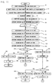
- the operation of the control unit CP in this case is explained along the flowchart of Fig. 11, wherein each step in the flowchart is abbreviated to simply "S".
- a user inputs recording data and color data with the keys on the keyboard IN to the control unit CP (S1). Successively, the user inputs, using the keys IN1 and IN2, the length x of the front margin or the length q of the rear margin in connection with the recording area of the tape TP (S2).
- the maximum length of the recording data is regarded as P (which corresponds to the length P of the recording area), and the recording data on each color (for example, yellow(Y), magenta(M), and cyan(C) colors) is divided into n-blocks and stored.
- the recording data is recorded while being developed for one block each in the print buffer.
- the process of finding the leading end of the ink ribbon IR is performed prior to the recording (S5).
- the carriage CA is first moved in the direction Y1 in Fig. 1 while pressing the thermal head HD against the platen 4 through the ink ribbon IR.
- the ink ribbon IR is successively sent out on the recording surface of the thermal head HD.
- the sensor SE detects the cyan color of the ink ribbon IR to locate the start thereof. After that, the feeding of the ink ribbon is controlled only by detecting the marks M1 indicating the boundaries between the ink regions by means of the sensor SE.
- the carriage CA is returned to the recording start position Pa (S6).
- a variable "m” of the number of blocks is at first defined as “1" (S7) to record the data of the m-th block in the color of yellow(Y) (S8). If the variable "m" is 1, the recording data of the first block is recorded.
- the thermal head HD is released from the tape TP and the carriage CA is returned to the recording start position Pa (S9).
- the data of the m-th block is recorded in the colors of magenta (M) and cyan (C) (S10-S13).
- M magenta
- C cyan
- the thermal head HD records the characters "ABCDE" in predetermined color(s) on the tape TP.
- the control unit CP judges that the variable "m" is 1 (S14).
- the control unit CP When the variable "m" is 1, which means the recording of the data of the first block (S14: YES), the control unit CP operates to feed the tape TP forward by the length (L-x) (S15) and execute a cutting process to the tape TP (S16) to cut away a redundant part of the tape TP provided ahead of the front margin having the length x. The tape TP is thus cut at a cutting point K1 shown in Fig. 9(b) by the cutting unit 5. Subsequently, the control unit CP performs the process in S17.
- the control unit CP operates to feed the tape TP by the length (P-(L-x)) as shown in Fig. 9(c) so that the tape TP is positioned at the recording start position Pa (S20) of the next block.
- the control unit CP counts the number of blocks by adding "1" to the variable "m” and advances the process to S8 to perform the recording of the data of the next block (S21).
- the control unit CP carries out the above processes in S8 through S13 again to cause the thermal head HD to record the characters "FGHI” in predetermined color(s) at the back of the recorded characters "ABCDE” on the tape TP as shown in Fig. 9(d).
- variable "m" is not 1 in S14, namely, "m" is 2 or more (S14: NO)
- the process of cutting the front margin from the tape TP is not required and the process is advanced to S22.
- the front margin is needed only when the variable "m" is 1 because it is the recording on the lead portion of the tape TP.
- the variable "m" is 2 or more, however, the total recording data has the length longer than the length of one block and the current recording is not made on the lead portion, so that the front margin is not needed providing ahead of the recording data.
- control unit CP detects whether the variable "m" is "n". If not "n", which means that the data of the last block has not been recorded yet (S22: NO), the tape TP is fed by the length P alone to the recording start position Pa for the recording of the data of the next block (S23). The control unit CP counts the number of blocks by adding "1" to the variable "m” (S24) and advances the process to S8 wherein the recording of the data of the next block is started.
- the tape TP is fed by the length (L+R+q) (S25). Then, the cutting unit 5 cuts the recorded part with the rear margin having the length q from the tape TP at the cutting point K1 as shown in Fig. (e), thereby terminating a series of the recording processes.
- the carriage CA mounting the thermal head HD provided with the heating elements arranged in a line in the main scanning direction of the tape TP can be moved in the sub-scanning direction perpendicular to the direction of arrangement of the heating elements.
- the heating elements of the thermal head HD are selectively caused to generate heat to melt the ink on the ink ribbon IR, recording desired images on the tape TP. Consequently, in the same manner as the line recording operation, the tape printing apparatus in the embodiment can use the ink ribbon at high efficiency and perform recording at high speed regardless of the length of the tape TP.
- the tape feeding direction is only a one-way, which requires no control of turning back the tape and of detecting the position of the tape. Accordingly, the apparatus can be made with a simple structure.
- the positioning control of recording depends on the moving precision of the carriage CA.
- the moving of the carriage CA by means of the timing belt 2e can be performed more accurately as compared with the case that the tape TP is fed in the sub-scanning direction.
- the apparatus can achieve recording of high quality even when color inks are superimposed on one another at the multi-color recording or when the recording data of the blocks are continuously recorded as to be jointed at each boundary of the adjacent ink regions.
- the apparatus can precisely produce the full-color recorded tape with predetermined front and rear margins and solve the disadvantages in the conventional line recording system and serial recording system.
- the recording apparatus of the present invention is not limited to the tape printing apparatus and may be applied to a general line thermal printer and the like, wherein ordinary recording paper or thermal recording paper is used as recording medium.
- the recording medium is preferably formed having a long length such that one end thereof is extended in the sub-scanning direction and another end is rolled, because a large amount of the recording medium can be used.
- the recording medium not limited to such the form, may be in a cut sheet form.
- the recording head may be one for an ink jet printer, for example, besides the thermal head HD.
- the ink ribbon IR may be a multi-color ink ribbon coated with a black ink in addition to the cyan(C), magenta(M), or yellow(Y) inks, or a single color ink ribbon.
- the apparatus is adapted such that the multi-color ink ribbon IR or the single color ink ribbon IR is selectively set in the carriage CA, and the set ink ribbon IR is passed between the thermal head HD and the tape TP during the movement of the carriage CA, the multi-color ink ribbon IR or the single color ink ribbon IR passes between the thermal head HD and the tape TP with the movement of the carriage CA, and the thermal head HD can carry out a recording operation on the tape TP.
- the recording can also be made in multi-color or single color depending on the selected tape TP.
Landscapes
- Impression-Transfer Materials And Handling Thereof (AREA)
- Common Mechanisms (AREA)
- Electronic Switches (AREA)
- Printers Characterized By Their Purpose (AREA)
- Handling Of Continuous Sheets Of Paper (AREA)
Abstract
Description
- The present invention relates to a recording medium cassette used in a recording apparatus which records characters, marks, etc. on a recording medium, and more particularly to a recording medium cassette used in a recording apparatus that has respective advantages of a line recording mode for performing recording with a recording head fixedly supported with respect to the recording medium and a serial recording mode for performing recording with a recording head allowed to scan a recording medium.
- Heretofore, there have been proposed many recording apparatus using various recording systems. One of those recording apparatus is a thermal printer wherein a thermal recording head melts ink applied on an ink ribbon so that the melted ink adheres to a recording medium. This thermal printer can record characters in a single or multiple color(s) on the recording medium by operating the recording head through a single-color ink ribbon or a full-color ink ribbon provided thereon with ink regions, each of which has a fixed length, that are arranged in order so that adjacent ink regions have different colors.
- As a recording mode of the thermal printer, there are a line recording mode and a serial recording mode. In the line recording mode is used a recording head provided with recording elements arranged corresponding to the width in a main scanning direction of a recording medium. As fixedly supporting this recording head, the printer performs printing on the recording medium that is fed in a sub-scanning direction perpendicular to the direction of arrangement of the recording elements. In the serial recording mode, on the other hand, a recording head provided with recording elements arranged corresponding to the predetermined length in a sub-scanning direction of a recording medium. While moving this recording head in a main scanning direction, the printer performs printing of a line on the recording medium fixedly supported and, after the one-line printing, feeds the recording medium in the sub-scanning direction. Then, the recording head is caused to reciprocate again in the main scanning direction to perform recording.
- In particular, if the thermal printer is a color thermal printer that uses a multi-color ink ribbon having color inks of magenta, cyan, and yellow arranged in order and carries out recording operation by superimposing the inks of different colors at the same position to blend into one another, such the printer has the following advantages and disadvantages.
- Advantages of the color thermal printer using the serial recording mode are that : (1) there is no limitation on the size of a recording head, in particular, in the main scanning direction, whereby a small-sized recording head can be made so that the manufacturing cost thereof is reduced; (2) the printer performs recording while moving the recording head with respect to the recording medium fixedly supported, achieving high precision of superimposition of inks and reducing misalignment of the inks on the recording medium; and (3) a recording head can make recording on the recording medium which is relatively long in the sub-scanning direction if the recording medium is fed in the sub-scanning direction after the one-line printing and then the recording head is moved back and forth in the main scanning direction. To the contrary, there are disadvantages that; (1) the recording speed is low and thus a period of time needed for recording is long; and (2) since most of the regions of the ink ribbon remain actually unused, the ratio of the used regions of the ink ribbon to the actually recorded area on the recording medium is small, resulting in high running costs.
- On the other hand, advantages of the color thermal printer using the line recording mode are that; (1) the printer can perform simultaneous recording in the main scanning direction, so that the recording speed is high and a period of time needed for recording is short; and (2) the ratio of the used regions of the ink ribbon to the actually recorded area on the recording medium is large, so that the recording efficiency is high and the running cost is reduced. Disadvantages are that; (1) since the printer feeds the recording medium in the sub-scanning direction while fixedly supporting the recording head, the recording medium must repeatedly be fed back and forth in the sub-scanning direction whenever the color of the ink ribbon is changed and there is a case that the recording medium is fed out of the printer in view of a feeding route in the printer, when a user may possibly touch the recording medium fed out of the printer, which causes displacement of recorded positions; (2) it is difficult to stop movement of the recording medium at a predetermined position when the recording medium is fed back and forth plural times in the sub-scanning direction to superimpose inks at the same position on the recording medium, so that the recording positional precision is so low that color displacement often occurs; and (3) if the recording medium is a roll of paper extending in a longitudinal direction, a special-purpose feeding device is required to rewind the roll of paper according to the change of diameter of the rolled paper and therefore color recording is generally difficult to perform on the continuous roll of paper.
- The present invention has been made in consideration of the above advantages and disadvantages and to provide a recording medium cassette used in a recording apparatus capable of performing recording on a recording medium regardless of the length thereof, and of achieving high speed recording, providing high recording positional precision, and reducing the running cost of an ink ribbon.
- Additional objects and advantages of the invention will be set forth in part in the description which follows and in part will be obvious from the description, or may be learned by practice of the invention. The objects and advantages of the invention may be realized and attained by means of the instrumentalities and combinations particularly pointed out in the appended claims.
- To achieve the purpose of the invention, there is provided a recording medium cassette used in a recording apparatus including a recording head for recording characters and others on a recording medium, the head being provided with a plurality of recording elements arranged in a first direction, a carriage mounting the recording head thereon, a first feeding device for moving the carriage in a second direction perpendicular to the first direction, a second feeding device for feeding the recording medium in the second direction and stopping the recording medium, the recording apparatus performing recording characters and others on the recording medium through the recording head while reciprocating the carriage by the first feeding device in the second direction, when feeding of the recording medium is stopped through the second feeding device, the recording medium cassette including an exposure part for exposing a part of the recording medium to allow the recording head to press against the recording medium within a predetermined recording area defined on the recording medium while the carriage is reciprocated through the first feeding device, and a holding member for holding the recording medium exposed through the exposure part.
- In the recording apparatus in which the recording medium cassette is mounted according to the present invention, while the carriage is reciprocated in the second direction perpendicular to the first direction, i.e., the arrangement direction of the recording elements within a recording area on the recording medium supported at rest, the recording elements arranged in a line corresponding to the width of the recording medium in the first scanning direction perform recording on the fixed recording medium. The recording apparatus can execute high-speed recording on the recording medium as fast as the case of the line recording operation. In particular, if the carriage mounting the recording head is moved in the second direction with respect to the fixed recording medium, it can perform movement at high precision as compared with the case where the recording medium is fed in the second direction with respect to the fixed recording head, so that an excellent recording quality can be provided.
- Furthermore, the recording medium cassette can be removably mounted in the recording apparatus so that the recording medium is held within the range where the carriage is reciprocated. Accordingly, after all recording medium accommodated in the cassette has been used, this used cassette can be exchanged for a new one accommodating an unused recording medium, whereby to use the recording apparatus again.
- According to another aspect of the present invention, there is provided a tape cassette used in a tape recording apparatus including a thermal head for recording characters and others on a long recording tape through an ink ribbon, the head being provided with a plurality of heating elements arranged in a first direction, a carriage mounting the thermal head thereon, a first feeding device for moving the carriage in a second direction perpendicular to the first direction, a second feeding device for feeding the recording tape in the second direction and stopping the recording tape, the tape recording apparatus performing recording characters and others on the recording tape through the thermal head while reciprocating the carriage by the first feeding device in the second direction, when feeding of the recording tape is stopped through the second feeding device, the recording tape cassette including a tape holding part for holding the recording tape in a rolled state, a tape discharge part for discharging the recording tape drawn out from the tape holding part, a pair of tape guide parts formed connecting the tape holding part and the tape discharge part and disposed opposite to and away from each other, an open part defined by the tape holding part, the tape discharge part, and the tape guide parts, wherein the open part exposes a part of the recording tape to allow the thermal head to press against the recording tape within a predetermined recording area defined on the recording tape while the carriage is reciprocated through the first feeding device, and the tape holding member and the tape discharge part hold both sides of the recording tape exposed through the open part.
- The accompanying drawings, which are incorporated in and constitute a part of this specification illustrate an embodiment of the invention and, together with the description, serve to explain the objects, advantages and principles of the invention.
- In the drawings,
- Fig. 1 is a perspective view of an embodiment of a tape printing apparatus embodying a recording apparatus using a recording medium cassette according to the present invention, a part of which is broken to show more clearly the inside components of the apparatus;
- Fig. 2 is plane view of a roller holder and others used in the tape printing apparatus;
- Fig. 3 is a schematic front view of an ink ribbon that is drawn from a ribbon cassette used in the tape printing apparatus;
- Fig. 4 is a perspective view of a tape cassette used in the tape printing apparatus;
- Fig. 5 is a cross sectional view of the tape cassette along the line A-A of Fig. 1;
- Fig. 6 is an explanatory view to show the relation between the feeding amount of a recording medium and the moving amount in a sub-scanning direction of a recording head used in the tape printing apparatus;
- Fig. 7 is a plane view of the recording medium and the recording head used in the tape printing apparatus to show the positional relation therebetween;
- Fig. 8 is a perspective enlarged view of a part of the recording medium used in the tape printing apparatus;
- Figs. 9(a) to 9(e) are explanatory views to show the relation between the feeding amount of the recording medium and the recorded area thereon; Fig. 9(a) shows the recording medium when recording on a first record area is completed, Fig. 9(b) shows the same when a front margin is cut, Fig. 9(c) shows the same when recording on a second record area is started, Fig. 9(d) shows the same when recording on the second record area is completed, and Fig. 9(e) shows the same when a rear margin is cut;
- Fig. 10 is a block diagram of an electrical structure of the recording apparatus in the embodiment; and
- Fig. 11 is a flow chart of operations of the recording apparatus in the embodiment.
-
- A detailed description of one preferred embodiment of a recording apparatus embodying the present invention will now be given referring to the accompanying drawings. The recording apparatus in this embodiment is applied to a tape printing apparatus for printing many images of characters or marks on a recording medium such as a tape, a thermal printer for printing the images on recording paper through an ink ribbon.
- Fig. 1 is a perspective view of an embodiment of a tape printing apparatus embodying the recording apparatus according to the present invention, a part of which is broken to show more clearly the inside components of the apparatus. Fig. 2 is plane view of a roller holder and others used in the tape printing apparatus. Fig. 3 is a schematic front view of an ink ribbon that is drawn from a ribbon cassette used in the tape printing apparatus. Fig. 4 is a perspective view of a tape cassette used in the tape printing apparatus. Fig. 5 is a cross sectional view of the tape cassette along the line A-A of Fig. 1.
- The tape printing apparatus has a box-
like body 1 provided with aleft side wall 1L, aright side wall 1R, afront side wall 1M, and arear side wall 1N. Thoseside walls body 1. - In the box-
like body 1, there are provided a carriage CA which mounts a thermal head HD, acarriage moving system 2 for moving the carriage CA, atape feeding system 3 for feeding a tape TP which is a recording medium, aplaten 4 arranged opposite to the thermal head through the tape TP, atape cutting unit 5 for cutting the tape TP, and aribbon feeding system 7 for feeding an ink ribbon IR with respect to the thermal head HD. - The
carriage moving system 2 is provided with a stepping motor attached to theside wall 1L from the outside thereof, amotor gear 2a mounted on a motor shaft SM1 penetrating theside wall 1L toward the inside of the box-like body 1, adrive pulley 2b meshing with themotor gear 2a, a timing belt supporting gear 2c formed integrally with thedrive pulley 2b, anidle pulley 2d mounted on a shaft J1 fixed on theside wall 1L and extended toward theside wall 1R, atiming belt 2e wound on the gear 2c and theidle pulley 2d and combined with the carriage CA, and carriage guide bars CA2 inserted in holes CA1 (two holes in this embodiment) formed in the carriage CA, extending along theside walls - When the stepping motor SM is driven to rotate the motor shaft SM1 and the
motor gear 2a clockwise (or counterclockwise) in Fig. 1, thedrive pulley 2b and the timing belt supporting gear 2c are moved round counterclockwise (or clockwise), so that thetiming belt 2e is moved round in the opposite direction to the direction Y1 (or in the direction Y1). The carriage CA is thus caused to move back and force along the carriage guide bars CA2 in accordance with the rotating direction of the motor shaft SM1 of the stepping motor SM. The movingsystem 2 moves the carriage CA mounting thereon a thermal head HD in the sub-scanning direction perpendicular to the direction of arrangement of heating elements provided on the thermal head HD. - In that case, the carriage CA is provided with a target CA4 for detecting the position of the carriage CA along the direction Y1. This target CA4 is arranged so as to pass the detection range of a carriage origin point detecting sensor CA5 disposed in a predetermined position inside of the
side wall 1L. With the sensor CA5, the tape printing apparatus in the present embodiment can detect that the carriage CA has passed the origin point. - The
tape feeding system 3 is provided with atape feed roller 3a and atape drive roller 3b disposed below theroller 3a for feeding tape TP in the sub-scanning direction (i.e., in the opposite direction to the direction Y1), both rollers extending along the direction indicated by an arrow Z1 perpendicular to the direction Y1, a stepping motor SN attached to theside wall 1R to rotate thetape drive roller 3b, a motor gear 3c mounted on a motor shaft SN1 penetrating theside wall 1R toward the inside of the box-like body 1, atape drive gear 3d (see Fig. 2) mounted on a roller shaft 3b1, on theside wall 1R side, that rotates integrally with thetape drive roller 3b, and atransmission gear 3e disposed between thetape drive gear 3d and the motor gear 3c and engaged with them respectively. - When the stepping motor SN is driven to rotate the motor shaft SN1 and the motor gear 3c counterclockwise in Fig. 1, the
transmission gear 3e engaging with the motor gear 3c is rotated clockwise, causing thetape drive gear 3d to rotate counterclockwise and thetape drive roller 3b counterclockwise in Fig. 1. If thetape drive roller 3b is made contact under pressure with thetape feed roller 3a, thetape drive roller 3b rotating counterclockwise in Fig. 1 feeds the tape TP in the sub-scanning direction (i.e., in the opposite direction to the direction Y1) in cooperation with thetape feed roller 3a. In this way, thetape feeding system 3 feeds the tape TP which is a recording medium in the sub-scanning direction. - In the present embodiment, the
tape drive roller 3b is held in aroller holder 3f disposed inside of theside walls tape drive roller 3b away from thetape feed roller 3a to make it easy to insert the tape TP between the bothrollers - The
roller holder 3f has a bottom plate 3f1 extending in a longitudinal direction of thetape drive roller 3b and bent portions 3f2 extending upward from both ends of the bottom plate 3f1, forming each of the bent portions 3f2 forming an L-shaped cross section. The roller shaft 3b1 is supported rotatably on those bent portions 3f2. A support shaft 3e1 of thetransmission gear 3e penetrates one of the bent portions 3f2 (right one in Fig. 2) to support it so that thetape drive gear 3d is rotated as a planet gear around thetransmission gear 3e while always engaging with it. A support shaft 3e2 provided extending from theside wall 1L side and positioned coaxially with the rotating center of the support shaft 3e1 supports the other bent portion 3f2. Along with theroller holder 3f, thetape drive roller 3b thus can be made to come into uniform contact under pressure with or move away from thetape feed roller 3a. - An operational plate 3f3 is formed extending from the right bent portion 3f2 toward the outside of the
side wall 1R. Acam 3h that rotates with an operatinglever 3g extending toward theside wall 1M is provided so as to be in contact with the operational plate 3f3. Under theroller holder 3f, a plurality of compressive coil springs 3k (two springs in this embodiment) are disposed. The biasing force of the coil springs 3k can cause thetape drive roller 3b to come into pressure-contact with thetape feed roller 3a. - Accordingly, When the operating
lever 3g is rotated in the direction of an arrow Y3 in Fig. 1, causing thecam 3h to move the operational plate 3f3 in the opposite direction to the direction of an arrow Y4, thus to move theroller holder 3f in the same direction, so that thetape drive roller 3b is made to come into pressure-contact with thetape feed roller 3a. To the contrary, when the operatinglever 3g is rotated in the opposite direction to the direction Y3 in Fig. 1, causing thecam 3h to move the operational plate 3f3 in the direction Y4, thus to move theroller holder 3f in the same direction, so that thetape drive roller 3b is released from thetape feed roller 3a. - As mentioned above, as the
tape drive gear 3d is rotating as a planet gear around thetransmission gear 3e, theroller holder 3f is rotated about the support shaft 3e1 of thetransmission gear 3e. Also in the case that thetape drive roller 3b is transferred from a released state with respect to thetape feed roller 3a to a pressure-contact state with the same, thetape drive roller 3b can feed the tape TP inserted between thetape drive roller 3b and thetape feed roller 3a in the sub-scanning direction (opposite to the direction Y1) upon reception of the driving force of the stepping motor SN. - The thermal head HD is disposed on the carriage CA opposite to the
platen 4 so that the thermal head HD extends from the carriage CA toward theside wall 1R. Heating elements that can generate heat per dot as recording elements are provided by the width corresponding to a line in the direction of an arrow Z1 on a recording surface of the thermal head HD. A ribbon detection sensor SE is disposed on the carriage CA on theside wall 1R side in substantially parallel to the thermal head HD. The ribbon detection sensor SE is arranged so that an ink ribbon IR is fed within the detection range of the sensor SE. The carriage CA is further provided with a motor CA3 for causing the thermal head HD, through a transmission mechanism (not shown) which transmits the driving force of the motor CA3 to the thermal head HD, to come into pressure-contact with theplaten 4 with the tape TP put thereon or to move away from theplaten 4. - In this case, the color ribbon cassette RC having the length corresponding to the width of the heating elements arranged in a line is set on the carriage CA on the
side wall 1R side without contact with the thermal head HD and the ribbon detection sensor SE. To put it concretely, a plurality of positioning pins CA6 (two pins in the present embodiment) provided on the carriage CA on theside wall 1R side are fitted in positioning recesses (not shown) of the color ribbon cassette RC, setting the ribbon cassette RC on the carriage CA on theside wall 1R side. - The
ribbon feeding system 7 feeds the ink ribbon IR held in the color ribbon cassette RC in the opposite direction to the direction Y1. Thisribbon feeding system 7 is provided with aspool 7a disposed downstream of the thermal head HD on the carriage CA and another spool 7b disposed upstream of the thermal head HD. Thespool 7a is fitted to a reel RC1 for winding used ribbon in the ribbon cassette RC and the spool 7b is fitted to a reel RC2 for supplying unused ribbon. - When a ribbon winding mechanism (not shown) causes the
spool 7a to rotate upon reception of the rotational driving force of the motor CA3, the reel RC1 allows thespool 7a to wind the ink ribbon IR that has been drawn out from the spool 7b and passed through the ribbon detection sensor SE and the recording surface side of the thermal head HD during recording operation. It is to be noted that the mechanism using a single motor of causing the thermal head on the carriage to come into contact with or be released from the recording medium and of winding the ink ribbon on the carriage is well known in the art, for example, in Japanese patent application laid-open No. 62(1987)-94374 and other patent publications. The detailed explanation thereof is accordingly omitted herein. - A
tape cassette 8 for holding the tape TP on a rear side and thetape feed roller 3a on a front side can be set in thebody 1 through an opening 1R1 formed in theside wall 1R. Thistape cassette 8 holds the tape TP with its end part rolled around anaxis 8a so that a forward end is drawn out in the sub-scanning direction from the rolled portion. Thetape cassette 8 thus can hold long tape TP if having the back end part in a rolled state. - The
tape cassette 8 is provided with right and leftguide portions front portion 8d which connects theguide portions cassette 8 and holds therein thetape feed roller 3a. Thoseguide portions body 1 when thetape cassette 8 is set moving from theside wall 1R side to theside wall 1L side in thebody 1. Thetape cassette 8 is formed with anopening 8e through which the thermal head HD is allowed to come into contact with the tape TP. Theplaten 4 is positioned extending in the sub-scanning direction within theopening 8e. In this state, the thermal head HD is moved in the range corresponding to theopening 8e. - Specifically, the
tape guide portions side wall 1L side of thetape cassette 8, two recesses (not shown) for positioning thetape cassette 8 are provided. When the shaft J1 and the shaft J2 formed extending from the timing belt support gear 2c toward theside wall 1R side are fitted in the recesses, thetape cassette 8 is set in place in thebody 1. - Fig. 5 shows the positional relation between the
tape guide portions platen 4 and others. Thetape guide portions platen 4 and the moving range of the thermal head HD. In the state where the thermal head HD is released from theplaten 4, thetape guide portion 8b disposed on the left side in Fig. 5 is placed at a position corresponding to the space between a lower surface of the thermal head HD and anupper surface 4a of theplaten 4, while a lower surface 8b2 of thetape guide portion 8b is away from theupper surface 4a of theplaten 4 at a slight distance (for example, 1-2 mm). - Since the
tape guide portion 8c on the opposite side (the right side in Fig. 5) does not come into contact with theplaten 4 when thetape cassette 8 is set in thebody 1, thetape guide portion 8c is designed to be thicker than thetape guide portion 8b in order to ensure the rigidity of thetape guide portion 8c made of plastic, for example. As concrete values, the thickness of thetape guide portion 8b is about 5mm, while that of thetape guide portion 8c is in the range of 7-10mm, so that a lower surface 8c2 of thetape guide portion 8c is positioned below theupper surface 4a of theplaten 4 as shown in Fig. 5. - In view of the above positional relation, the thermal head HD should be released from the
platen 4 by the distance so that thetape guide portion 8c can pass through the space between the thermal head HD and theplaten 4 at the time of setting of thetape cassette 8 in thebody 1. The motor CA3 is therefore driven to move the thermal head HD sufficiently away from theplaten 4. - A
cutting unit 5 for cutting a forward part of the tape TP is provided outside of theside wall 1M. Thiscutting unit 5 includes a fixedblade 5b, amovable blade 5a, and a lever connected to themovable blade 5a. Upon drive of adrive source 5d (for example, an electromagnetic solenoid, etc.), ablade moving lever 5c is caused to move themovable blade 5 up or down with respect to the fixedblade 5b, thereby to cut the part of the tape TP drawn out through a discharge port 1M1 formed in theside wall 1M. - The
cutting unit 5 is constructed as above for the purpose of cutting the recorded part of the tape TP by the length including a length x of a front margin provided ahead of the recording initial point of the recorded part of the tape TP or a length q of a rear margin provided following after the recording termination point of the recorded part, the length x or q having been optionally set with a keyboard IN and the like. A control unit CP (see Fig. 10) which will be mentioned later operates thedrive source 5d to drive thelever 5c, thereby moving themovable blade 5a with respect to the fixedblade 5b. Thelever 5c may be constructed to be operated by a user as the occasion demands. - Fig. 6 is an explanatory view of showing the positional relation among the
blades rollers blades blades - Fig. 7 simply shows the relation among the width W1 of the tape TP, the width W2 of a recordable range of the tape TP, the recording width W3 of the thermal head HD, and the width W4 of the
platen 4. This shows that recording can be made over the recordable width W2 because it is determined to be narrower than the recording width W3. In other words, the length in a main scanning direction (a first direction) of the tape TP (i.e., the tape width W1) is set to be larger than the width W3 of the thermal head HD and the recordable width W2 is previously set to be smaller than the width W3 in the main scanning direction of the tape TP, the thermal head HD can record images on the tape throughout the width W2. The width W4 of theplaten 4 being smaller than the tape width W1, the thermal head HD is prevented from recording on theplaten 4 on which no tape TP exists, so that theplaten 4 is not scorched, thereby causing no adhesion of ink to theplaten 4. - Fig. 8 shows a part of the tape TP which has a recordable portion TP1 having the width W2, a right and left blank margin portions TP2 and TP3, which constitute the upper surface of the tape TP. Adhesive material is applied on the back side of the recorcable portion TP1 and the right and left margin portions TP2 and TP3, which a releasable sheet TP4 is attached to. Half-cut lines TP5 are formed at the boundaries of the recordable portion TP1 with respect to the blank margin portions TP2 and TP3, whereby to make easy to separate the recordable portion TP1 from the margin portions TP2 and TP3. In this case, a user pulls the margin portions TP2 and TP3 while holding the recordable portion TP1, cutting the half-cut line TP5. The unnecessary margin portions TP2 and TP3 can easily be removed from the recordable portion TP1. Peeling off the releasable sheet TP4 from the recordable portion TP1, this recordable portion TP1 of the tape TP can be stuck through the adhesive material onto things, e.g., a spine of files. The adhesive material may be a double-sided adhesive tape besides a common adhesive agent.
- Next, the ribbon cassette RC is explained. This cassette RC accommodates therein an ink ribbon IR on which a plurality of color ink regions consisted of, for example, cyan (C), magenta (M), and yellow (Y) inks which are arranged in order as shown in Fig. 3. When the reel RC1 is rotated by the driving force of the drive motor CA3 (see Fig. 3), as mentioned above, the ink ribbon IR pulled out from the reel RC2 is wound on the reel RC1 after passed the sensor SE and the thermal head HD.
- The sensor SE is constructed of a light emitting element SE1 which applies light to the ink ribbon IR and a light receiving element SE2 which receives the light transmitted through the ink ribbon IR. The sensor SE is disposed on the carriage CA so as to jut from the carriage CA toward the
side wall 1R side in Fig. 1. When the ribbon cassette RC is set on the carriage CA, the elements SE1 and SE2 of the sensor SE are fitted inside the ribbon cassette RC. The light emitted by the light emitting element SE1 is transmitted through the ink ribbon IR existing between the elements SE1 and SE2, and irradiates the light receiving element SE2. - Specifically, the light emitting element SE1 is, for example, a red LED which emits red light. The light receiving element SE2 transmits signals to the control unit CP. The signals are representative of voltage values responsive to the amount of light transmitted through the ink ribbon IR. The control unit CP is constituted to distinguish the color of cyan (C) of the ink ribbon IR in the ribbon cassette RC from the other colors of magenta (M) and yellow (Y).
- For example, when a magenta (M) or yellow (Y) ink region of the ink ribbon IR is fed to the detection point of the sensor SE (i.e., between the light emitting element SE1 and the light receiving element SE2), the irradiation light of the light emitting element is not so blocked off by the magenta (M) or yellow (Y) ink region. The light receiving element SE2 outputs a large signal, accordingly. When a cyan (C) ink region of the ink ribbon IR is fed to the detection point, on the other hand, fully blocking the irradiation light of the light emitting element SE1, the light receiving element SE2 outputs a small signal. Accordingly, the control unit CP can distinguish the color of cyan (C) from the other colors of magenta (M) and yellow (Y) of the ink ribbon IR.
- The ink ribbon IR is provided with color ink regions each having the cyan (C), magenta (M) and yellow (Y) inks with almost the same length and detection marks M1 disposed at boundaries of the adjacent ink regions as shown in Fig. 3. The detection mark M1 in the present embodiment is formed of a transparent portion Ma, a black portion Mb, and a transparent portion Ma disposed in this order. The transparent portion Ma when comes to the detection point of the sensor SE transmits the irradiation light of the light emitting element SE1. To the contrary, the black portion Mb when comes to the detection point blocks off the irradiation light of the element SE1. Thus, the control unit CP can detect the mark M1 upon reception of the output signal of the light receiving element SE2, representative of the voltage value corresponding to the transparent portion Ma, the black portion Mb, and the transparent portion Ma.
- On the end portion of the ink ribbon IR shown in Fig. 3, there is provided with an end mark M2 different from the mark M1. In this case, the end mark M2 is formed following the last cyan (C) region having a length T.
- The end mark M2 is, for example, formed of a plurality of transparent portions Ma and black portions Mb, which are alternately arranged in order. The transparent portion Ma when fed to the detection point of the sensor SE transmits the irradiation light of the light emitting element SE1. To the contrary, the black portion Mb when fed to the detection point blocks off the irradiation light of the element SE1. When the light receiving element SE2 receives the output signal representative of the voltage value corresponding to the transparent portion Ma, the black portion Mb, the transparent portion Ma ··· ···, the control unit CP can thus detect the mark M2.
- Next, an electrical structure of the tape printing apparatus is explained with reference to Fig. 10. The control unit CP, having a central control unit (referred to as CPU hereinafter) as a core, is connected to the keyboard IN which is an input device, a memory CG-ROM for generating character images, which is used for displaying and printing characters and the like, a display LCD, a motor drive circuit MK for drive motors CA3, SN, and SM used to feed the ink ribbon IR and the like, the thermal head HD, the sensors SE, CA5, and others, and the
drive source 5d for operating thelever 5c. The control unit CP includes the CPU, a read only memory (ROM), and a random access memory (RAM). The control unit CP controls a recording operation, as mentioned later, using the heating elements within the recording area on the tape TP held at rest, while causing the carriage CA to reciprocate in a sub-scanning direction (a second direction). - The motor drive circuit MK is controlled by the control unit CP to drive the drive motors CA3, SM, and SN. For example, when the control unit CP drives the drive motor CA3 through the motor drive circuit MK by a predetermined amount, the reel RC2 is rotated by a predetermined amount, thereby feeding the ink ribbon IR by a predetermined amount. At this time, the control unit CP can detect the feeding amount of the ink ribbon IR by detecting the driving amount of the drive motor CA3. When the control unit CP drives the drive motor SM through the motor drive circuit MK by a predetermined amount, the
timing belt 2e is moved round by a predetermined amount, bring the thermal head to a predetermined position. Furthermore, the drive motor SN when driven by a predetermined amount under control of the control unit CP feeds the tape TP by a predetermined amount. - The keyboard IN includes a key IN1 for inputting the length x of the front margin shown in Fig. 9 and a key IN2 for inputting the length q of the rear margin following the recording termination point. With the key IN1, specifically, the length x to be provided ahead of the recording initial point is set. With the key IN2, the length q to be provided after the recording termination point is set. The sensors SE, CA5, and others detect a predetermined color of the ink ribbon IR and an ribbon end or detect the origin point of the carriage CA, and transmit detection signals to the control unit CP.
- The CG-ROM serves to a character generator which generates image data of the characters and others to be displayed or printed. The CG-ROM converts the data representative of characters and others to image data and transmits it to the control unit CP.
- The ROM stores a control program for driving the drive motor SM and others, a display program for causing the display LCD to display the characters and others input with the keys on the input device IN such as the keyboard, and other various programs needed for the operation of the tape printing apparatus. When operates in accordance with the program of driving the
cutting unit 5, the control unit CP constitutes a cutting controller. This control unit CP drives thecutting unit 5 after feeding the tape TP in the sub-scanning direction by the length corresponding to the amount set with the key IN1 or IN2. - The RAM stores various data memory regions, e.g., a display buffer, a print buffer, etc. In those memory regions, for example, the image data is temporarily stored and the recording data to be supplied to the heating elements are stored by dividing into plural parts each having the data quantity corresponding to the moving distance P of the carriage CA. It is to be noted that the control unit CP is preferably designed to receive the data of characters and others transmitted from an exterior host computer.
- Next, the operation of the tape printing apparatus in the present embodiment is explained. In Fig. 1, when the motor shaft SM1 of the stepping motor SM is rotated counterclockwise, the
drive pulley 2b is rotated clockwise. As the rotation of thepulley 2b, thetiming belt 2e is rotated, moving the carriage CA in the direction of the arrow Y1 in Fig. 1 toward the roll side of the tape TP, when the thermal head HD performs recording on the tape TP. - Prior to the recording operation, the recording origin point is detected. Specifically, the position where the right end of the target CA4 provided on the carriage CA is detected by the carriage origin sensor CA5 is considered as a reference point. The position where the carriage moved rightward by the predetermined number of pulses (for example, 10 pulses) arrives is regarded as the recording start position Pa (see Fig. 6).
- While the carriage CA carries the thermal head HD as pressed against the tape TP by the recording length P (see Fig. 6) in the sub-scanning direction of the tape TP (in the direction Y1), the heating elements of the thermal head HD are selectively caused to generate heat per dot, melting the ink of the ink ribbon IR per dot and transferring the melted ink onto the tape TP in the main scanning direction of the tape TP, so that desired images are recorded in turn in the direction (in the direction Y1) perpendicular to the direction of arrangement of the heating elements (in the direction Z1). As the movement of the carriage CA, while the ink ribbon IR is caused to pass between the thermal head HD and the tape TP, the heating elements carry out ink recording on the tape TP.
- Since the tape TP is held with one end thereof rolled and another end pinched between the
tape drive roller 3b and thetape feed roller 3a, as mentioned above, sufficient tension is applied to the tape TP. Furthermore, the thermal head HD carries out recording while moving from the end side of the tape pinched between therollers - After completion of recording, at the recording area end position Pb in the direction Y1, the control unit CP operates to release the thermal head HD from the tape TP and then to return the carriage CA to the recording start position Pa in the sub-scanning direction of the tape TP (in the opposite direction to the direction Y1). Simultaneously, the control unit CP operates to feed the tape P1 by a predetermined amount (the length P of the recording area) in the sub-scanning direction (the direction Y1). The thermal head HD is then pressed against the tape TP again. Sequentially, while the carriage CA is moved in the sub-scanning direction (the direction Y1), the thermal head HD performs recording on the tape P1 as mentioned above to form character images continuously arranged thereon.
- Repeating the above operations, images such as characters, symbols, etc. are printed on the tape P1. At this time, it is desired to perform a banding process for keeping the continuity of the recorded images at the joints thereof. The feeding amount of the tape TP in the sub-scanning direction is set based on the moving amount of the carriage CA within the recording area.
- Note that, in the case of a multi-color recording operation, the above operation is repeatedly carried out on the same area of the ink ribbon IR, considering the area having the length P as one block, for three colors of yellow(Y), magenta(M), and cyan(C). After recording in three colors, the
tape drive roller 3b and thetape feed roller 3a, which are in contact under pressure with each other, feed the tape TP rightwards in Fig. 1. In this case, the moving distance P of the carriage CA within the recording area is determined to substantially equal to the length T of each ink region of the color ink ribbon IR. When the carriage CA is moved by the distance P within the recording area, the position of the carriage CA is the end of the current ink region. - The above operations are regarded as a recording cycle of one block of the tape TP, and repeated if the full length of the recording data is longer than the length P of the recording area. Accordingly, when the thermal head HD records images on the tape TP through the heating elements, the recording data to be supplied to the heating elements is divided into plural parts so that each part has the data quantity corresponding to the moving distance of the carriage CA within the recording area.
- Prior to the color recording, the leading end of the ink ribbon IR requires finding in order to perform the recording in the colors of yellow (Y), magenta (M), cyan (C) in this order. The finding the leading end of the ink ribbon IR is controlled by detecting the end of the cyan region to derive the start of the yellow region and, after this, by detecting the marks M1 representative of the boundary between adjacent regions having different colors. Since the ink ribbon IR is coated with three color inks, i.e., the yellow(Y), magenta(M), and cyan(C) inks in order by the same length T each and provided with the marks M1 whereby to detect the boundary between the adjacent color ink regions by sensing the change of color, the ribbon detection sensor SE constructed of the light emitting element SE1 formed of a red LED and the light receiving element SE2 formed of a through-beam type photosensor can detect the cyan color which has complementary relation to a red color, the detection marks M1 and the end mark M2.
- The length T of the ink region is desired to be slightly longer than the length P of the recording area. This prevents the occurrence of recording errors due to the shortage of ink region. Specifically, if the length T of the ink region is designed to be completely equal to the length P of the recording area, the length T may become shorter than the length P for various reasons, resulting in the shortage of ink region.
- Next, the processes of recording and the operation thereof are described with reference to Figs. 9 and 11. Fig. 9(a) shows the tape TP after completion of recording of a first block. Fig. 9(b) shows the tape TP fed forward in consideration of the length x of the front margin after the completion of recording of the first block. Fig. 9(c) shows the same at the commencement of recording of a second block. Fig. 9(d) shows the same after completion of recording of the second block. Fig. 9(e) shows the same fed in consideration of the length q of the rear margin after the completion of recording of the second block. The operation of the control unit CP in this case is explained along the flowchart of Fig. 11, wherein each step in the flowchart is abbreviated to simply "S".
- At first, a user inputs recording data and color data with the keys on the keyboard IN to the control unit CP (S1). Successively, the user inputs, using the keys IN1 and IN2, the length x of the front margin or the length q of the rear margin in connection with the recording area of the tape TP (S2). After the completion of inputting the data, the control unit CP performs in the RAM the process of dividing the recording data into plural parts corresponding to the recordable length (S3). In this process, the number of divided parts with respect to the full length Q of the recording data and the residual length R are given by the following expression;
- Specifically, the maximum length of the recording data is regarded as P (which corresponds to the length P of the recording area), and the recording data on each color (for example, yellow(Y), magenta(M), and cyan(C) colors) is divided into n-blocks and stored. The recording data is recorded while being developed for one block each in the print buffer.
- When a recording command is applied to the control unit CP (S4), subsequently, the process of finding the leading end of the ink ribbon IR is performed prior to the recording (S5). The carriage CA is first moved in the direction Y1 in Fig. 1 while pressing the thermal head HD against the
platen 4 through the ink ribbon IR. The ink ribbon IR is successively sent out on the recording surface of the thermal head HD. The sensor SE detects the cyan color of the ink ribbon IR to locate the start thereof. After that, the feeding of the ink ribbon is controlled only by detecting the marks M1 indicating the boundaries between the ink regions by means of the sensor SE. When the leading end of the ink ribbon IR is found, the carriage CA is returned to the recording start position Pa (S6). - Subsequently, the recording data developed in the print buffer is recorded in turn. A variable "m" of the number of blocks is at first defined as "1" (S7) to record the data of the m-th block in the color of yellow(Y) (S8). If the variable "m" is 1, the recording data of the first block is recorded. Upon completion of recording in yellow, the thermal head HD is released from the tape TP and the carriage CA is returned to the recording start position Pa (S9). Similarly, the data of the m-th block is recorded in the colors of magenta (M) and cyan (C) (S10-S13). Specifically, as shown in Fig. 9(a), the thermal head HD records the characters "ABCDE" in predetermined color(s) on the tape TP. After completion of the recording of the data of the m-th block, the control unit CP judges that the variable "m" is 1 (S14).
- When the variable "m" is 1, which means the recording of the data of the first block (S14: YES), the control unit CP operates to feed the tape TP forward by the length (L-x) (S15) and execute a cutting process to the tape TP (S16) to cut away a redundant part of the tape TP provided ahead of the front margin having the length x. The tape TP is thus cut at a cutting point K1 shown in Fig. 9(b) by the
cutting unit 5. Subsequently, the control unit CP performs the process in S17. - In S17, the judgement is made as to whether the variable "m" is equal to "n", specifically, whether the recording of the data of the last block is terminated (S17). If the variable "m" is not equal to "n" (S17: NO), which means the recording in the last block has not been performed yet, the control unit CP operates to feed the tape TP by the length (P-(L-x)) as shown in Fig. 9(c) so that the tape TP is positioned at the recording start position Pa (S20) of the next block. The control unit CP counts the number of blocks by adding "1" to the variable "m" and advances the process to S8 to perform the recording of the data of the next block (S21). The control unit CP carries out the above processes in S8 through S13 again to cause the thermal head HD to record the characters "FGHI" in predetermined color(s) at the back of the recorded characters "ABCDE" on the tape TP as shown in Fig. 9(d).
- On the other hand, if the variable "m" is equal to "n" in S17, which means that only the data of the first block is to be recorded, the total length Q of the recording data comes to the residual length R according to the above expression. The tape TP is therefore fed by the length (x+R+q) (S18). The
cutting unit 5 then cuts the recorded part with the rear margin having the length q from the tape TP at the cutting point K1. A series of the recording processes mentioned above is completed. - If the variable "m" is not 1 in S14, namely, "m" is 2 or more (S14: NO), the process of cutting the front margin from the tape TP is not required and the process is advanced to S22. Specifically, the front margin is needed only when the variable "m" is 1 because it is the recording on the lead portion of the tape TP. When the variable "m" is 2 or more, however, the total recording data has the length longer than the length of one block and the current recording is not made on the lead portion, so that the front margin is not needed providing ahead of the recording data.
- In S22, similarly to S17, the control unit CP detects whether the variable "m" is "n". If not "n", which means that the data of the last block has not been recorded yet (S22: NO), the tape TP is fed by the length P alone to the recording start position Pa for the recording of the data of the next block (S23). The control unit CP counts the number of blocks by adding "1" to the variable "m" (S24) and advances the process to S8 wherein the recording of the data of the next block is started.
- When the variable "m" is "n" (S22: YES), which means the recording of the data of the last block (the second block in the present embodiment) is completed (see Fig. 9(d)), the tape TP is fed by the length (L+R+q) (S25). Then, the
cutting unit 5 cuts the recorded part with the rear margin having the length q from the tape TP at the cutting point K1 as shown in Fig. (e), thereby terminating a series of the recording processes. - As mentioned above, in the tape printing apparatus in the above embodiment, the carriage CA mounting the thermal head HD provided with the heating elements arranged in a line in the main scanning direction of the tape TP can be moved in the sub-scanning direction perpendicular to the direction of arrangement of the heating elements. Also, while the carriage CA returned to the recording start position is moved in the sub-scanning direction within the recording area of the tape TP held at rest, the heating elements of the thermal head HD are selectively caused to generate heat to melt the ink on the ink ribbon IR, recording desired images on the tape TP. Consequently, in the same manner as the line recording operation, the tape printing apparatus in the embodiment can use the ink ribbon at high efficiency and perform recording at high speed regardless of the length of the tape TP.
- In the tape printing apparatus which performs the recording control and the tape feeding control mentioned above, the tape feeding direction is only a one-way, which requires no control of turning back the tape and of detecting the position of the tape. Accordingly, the apparatus can be made with a simple structure. The positioning control of recording depends on the moving precision of the carriage CA. The moving of the carriage CA by means of the
timing belt 2e can be performed more accurately as compared with the case that the tape TP is fed in the sub-scanning direction. As a result, the apparatus can achieve recording of high quality even when color inks are superimposed on one another at the multi-color recording or when the recording data of the blocks are continuously recorded as to be jointed at each boundary of the adjacent ink regions. - Furthermore, the apparatus can precisely produce the full-color recorded tape with predetermined front and rear margins and solve the disadvantages in the conventional line recording system and serial recording system.
- The present invention may be embodied in other specific forms without departing from the spirit or essential characteristics thereof. For instance, the recording apparatus of the present invention is not limited to the tape printing apparatus and may be applied to a general line thermal printer and the like, wherein ordinary recording paper or thermal recording paper is used as recording medium. In particular, the recording medium is preferably formed having a long length such that one end thereof is extended in the sub-scanning direction and another end is rolled, because a large amount of the recording medium can be used. However, the recording medium, not limited to such the form, may be in a cut sheet form.
- The recording head may be one for an ink jet printer, for example, besides the thermal head HD. The ink ribbon IR may be a multi-color ink ribbon coated with a black ink in addition to the cyan(C), magenta(M), or yellow(Y) inks, or a single color ink ribbon. If the apparatus is adapted such that the multi-color ink ribbon IR or the single color ink ribbon IR is selectively set in the carriage CA, and the set ink ribbon IR is passed between the thermal head HD and the tape TP during the movement of the carriage CA, the multi-color ink ribbon IR or the single color ink ribbon IR passes between the thermal head HD and the tape TP with the movement of the carriage CA, and the thermal head HD can carry out a recording operation on the tape TP. The recording can also be made in multi-color or single color depending on the selected tape TP.
- The foregoing description of the preferred embodiment of the invention has been presented for purposes of illustration and description. It is not intended to be exhaustive or to limit the invention to the precise form disclosed, and modifications and variations are possible in light of the above teachings or may be acquired from practice of the invention. The embodiment chosen and described in order to explain the principles of the invention and its practical application to enable one skilled in the art to utilize the invention in various embodiments and with various modifications as are suited to the particular use contemplated. It is intended that the scope of the invention be defined by the claims appended hereto, and their equivalents.
Claims (10)
- A recording medium cassette used in a recording apparatus including a recording head for recording characters and others on a recording medium, the head being provided with a plurality of recording elements arranged in a first direction, a carriage mounting the recording head thereon, a first feeding device for moving the carriage in a second direction perpendicular to the first direction, a second feeding device for feeding the recording medium in the second direction and stopping the recording medium, the recording apparatus performing recording characters and others on the recording medium through the recording head while reciprocating the carriage by the first feeding device in the second direction, when feeding of the recording medium is stopped through the second feeding device, the recording medium cassette including:an exposure part for exposing a part of the recording medium to allow the recording head to press against the recording medium within a predetermined recording area defined on the recording medium while the carriage is reciprocated through the first feeding device; anda holding member for holding the recording medium exposed through the exposure part.
- A recording medium cassette according to claim 1, wherein the recording medium is a long recording tape.
- A recording medium cassette according to claim 2, further comprising:a tape holding part for holding the recording tape in a rolled state;a tape discharge part for discharging the recording tape drawn out from the tape holding part; anda pair of tape guide parts formed connecting the tape holding part and the tape discharge part and disposed opposite to and away from each other;
wherein the exposure part is constituted of an open part defined by the tape holding part, the tape discharge part, and each of the tape guide parts. - A recording medium cassette according to claim 3, wherein the holding member includes a tape shaft which is disposed in the tape holding part and on which the recording tape is wound and a tape feed roller which is disposed in the tape discharge part and feeds the recording tape as holding it.
- A recording medium cassette according to claim 3, wherein the recording head of the recording apparatus is moved reciprocating within the open part ,
a recording start point and a recording end point of the recording head preferably exist in the open part, and the recording head is moved reciprocating between the recording start and end points. - A recording medium cassette according to claim 3, wherein each of the guide parts has a guide groove for guiding a side portion of the recording tape.
- A recording medium cassette according to one of claims 3 to 6, wherein the recording head performs recording of characters and others on the recording tape through the recording elements during movement of the recording head from a tape discharge part side to a tape holding part side.
- A recording medium cassette according to one of claims 2 to 7, wherein a width of the recording tape is determined to be wider than a recording width of the recording elements of the recording head,
a width of the predetermined recording area of the recording tape is preferably determined to be smaller than the recording width of the recording elements of the recording head. - A recording medium cassette according to claim 8, wherein the recording apparatus includes a platen for supporting the recording tape on an opposite side to the recording head, and the platen is formed having a width smaller than the width of the recording tape.
- A tape cassette used in a tape recording apparatus including a thermal head for recording characters and others on a long recording tape through an ink ribbon, the head being provided with a plurality of heating elements arranged in a first direction, a carriage mounting the thermal head thereon, a first feeding device for moving the carriage in a second direction perpendicular to the first direction, a second feeding device for feeding the recording tape in the second direction and stopping the recording tape,
the tape recording apparatus performing recording characters and others on the recording tape through the thermal head while reciprocating the carriage by the first feeding device in the second direction, when feeding of the recording tape is stopped through the second feeding device, the recording tape cassette including:a tape holding part for holding the recording tape in a rolled state;a tape discharge part for discharging the recording tape drawn out from the tape holding part;a pair of tape guide parts formed connecting the tape holding part and the tape discharge part and disposed opposite to and away from each other;an open part defined by the tape holding part, the tape discharge part, and the tape guide parts;
wherein the open part exposes a part of the recording tape to allow the thermal head to press against the recording tape within a predetermined recording area defined on the recording tape while the carriage is reciprocated through the first feeding device; andthe tape holding member and the tape discharge part hold both sides of the recording tape exposed through the open part.
Applications Claiming Priority (3)
| Application Number | Priority Date | Filing Date | Title |
|---|---|---|---|
| JP31974097 | 1997-11-20 | ||
| JP31974097A JPH11151844A (en) | 1997-11-20 | 1997-11-20 | Recording medium-housing cassette |
| JP319740/97 | 1997-11-20 |
Publications (2)
| Publication Number | Publication Date |
|---|---|
| EP0917959A2 true EP0917959A2 (en) | 1999-05-26 |
| EP0917959A3 EP0917959A3 (en) | 2000-04-12 |
Family
ID=18113655
Family Applications (1)
| Application Number | Title | Priority Date | Filing Date |
|---|---|---|---|
| EP98121984A Withdrawn EP0917959A3 (en) | 1997-11-20 | 1998-11-19 | Recording medium cassette |
Country Status (2)
| Country | Link |
|---|---|
| EP (1) | EP0917959A3 (en) |
| JP (1) | JPH11151844A (en) |
Cited By (2)
| Publication number | Priority date | Publication date | Assignee | Title |
|---|---|---|---|---|
| EP2660063A1 (en) * | 2012-05-02 | 2013-11-06 | Brother Kogyo Kabushiki Kaisha | Adhesive tape cartridge |
| US9193557B2 (en) | 2012-05-02 | 2015-11-24 | Brother Kogyo Kabushiki Kaisha | Adhesive tape cartridge |
Families Citing this family (1)
| Publication number | Priority date | Publication date | Assignee | Title |
|---|---|---|---|---|
| JP6213159B2 (en) * | 2013-10-31 | 2017-10-18 | ブラザー工業株式会社 | Printing device |
Citations (1)
| Publication number | Priority date | Publication date | Assignee | Title |
|---|---|---|---|---|
| JPH06294374A (en) | 1993-04-09 | 1994-10-21 | Japan Energy Corp | Power generator |
Family Cites Families (3)
| Publication number | Priority date | Publication date | Assignee | Title |
|---|---|---|---|---|
| EP0451830B1 (en) * | 1990-04-11 | 1995-07-19 | Seiko Epson Corporation | Printing apparatus |
| GB2311039B (en) * | 1996-03-13 | 2000-01-19 | Esselte Nv | Tape printing apparatus and tape holding case |
| JPH10291707A (en) * | 1997-04-15 | 1998-11-04 | Brother Ind Ltd | Web roll and web roll containing cassette |
-
1997
- 1997-11-20 JP JP31974097A patent/JPH11151844A/en not_active Withdrawn
-
1998
- 1998-11-19 EP EP98121984A patent/EP0917959A3/en not_active Withdrawn
Patent Citations (1)
| Publication number | Priority date | Publication date | Assignee | Title |
|---|---|---|---|---|
| JPH06294374A (en) | 1993-04-09 | 1994-10-21 | Japan Energy Corp | Power generator |
Cited By (3)
| Publication number | Priority date | Publication date | Assignee | Title |
|---|---|---|---|---|
| EP2660063A1 (en) * | 2012-05-02 | 2013-11-06 | Brother Kogyo Kabushiki Kaisha | Adhesive tape cartridge |
| US9193557B2 (en) | 2012-05-02 | 2015-11-24 | Brother Kogyo Kabushiki Kaisha | Adhesive tape cartridge |
| US9221649B2 (en) | 2012-05-02 | 2015-12-29 | Brother Kogyo Kabushiki Kaisha | Adhesive tape cartridge |
Also Published As
| Publication number | Publication date |
|---|---|
| EP0917959A3 (en) | 2000-04-12 |
| JPH11151844A (en) | 1999-06-08 |
Similar Documents
| Publication | Publication Date | Title |
|---|---|---|
| US7277109B2 (en) | Thermal transfer printer | |
| EP1580012B1 (en) | Printer | |
| US4507668A (en) | Thermal printer | |
| EP1749674A2 (en) | Print apparatus, ribbon movement control device, ribbon film, ribbon movement control method, and program | |
| EP1584479B1 (en) | Printer | |
| JPH0867038A (en) | Rolled paper type recorder | |
| EP0917959A2 (en) | Recording medium cassette | |
| EP0917960A1 (en) | Recording apparatus | |
| JP2014094487A (en) | Image formation device and image formation method | |
| EP1586456A1 (en) | Printer and printing method | |
| JP4424156B2 (en) | Printer | |
| JP4363284B2 (en) | Printer | |
| JPH11151839A (en) | Recording apparatus | |
| JP4367301B2 (en) | Printer and recording medium conveying apparatus | |
| JP4200640B2 (en) | Printer | |
| JPH11151834A (en) | Medium to be recorded | |
| JP2024130659A (en) | TAPE PRINTING APPARATUS AND METHOD FOR CONTROLLING TAPE PRINTING APPARATUS | |
| JP4501608B2 (en) | Printer | |
| JPS60180867A (en) | Image-forming device | |
| JP3779607B2 (en) | Thermal transfer printer | |
| JP2005271452A (en) | Printer | |
| JPH11334188A (en) | Color printer | |
| JP2005271503A (en) | Printer | |
| JPH0811405A (en) | Transfer type printer | |
| JP2005297315A (en) | Printer |
Legal Events
| Date | Code | Title | Description |
|---|---|---|---|
| PUAI | Public reference made under article 153(3) epc to a published international application that has entered the european phase |
Free format text: ORIGINAL CODE: 0009012 |
|
| AK | Designated contracting states |
Kind code of ref document: A2 Designated state(s): AT BE CH CY DE DK ES FI FR GB GR IE IT LI LU MC NL PT SE |
|
| AX | Request for extension of the european patent |
Free format text: AL;LT;LV;MK;RO;SI |
|
| PUAL | Search report despatched |
Free format text: ORIGINAL CODE: 0009013 |
|
| AK | Designated contracting states |
Kind code of ref document: A3 Designated state(s): AT BE CH CY DE DK ES FI FR GB GR IE IT LI LU MC NL PT SE |
|
| AX | Request for extension of the european patent |
Free format text: AL;LT;LV;MK;RO;SI |
|
| RIC1 | Information provided on ipc code assigned before grant |
Free format text: 7B 41J 3/407 A, 7B 41J 15/04 B |
|
| AKX | Designation fees paid | ||
| REG | Reference to a national code |
Ref country code: DE Ref legal event code: 8566 |
|
| STAA | Information on the status of an ep patent application or granted ep patent |
Free format text: STATUS: THE APPLICATION IS DEEMED TO BE WITHDRAWN |
|
| 18D | Application deemed to be withdrawn |
Effective date: 20001013 |