EP0917349B1 - Document image data processing for detecting, extracting and coupling of regions with same characteristics - Google Patents
Document image data processing for detecting, extracting and coupling of regions with same characteristicsInfo
- Publication number
- EP0917349B1 EP0917349B1 EP98309325A EP98309325A EP0917349B1 EP 0917349 B1 EP0917349 B1 EP 0917349B1 EP 98309325 A EP98309325 A EP 98309325A EP 98309325 A EP98309325 A EP 98309325A EP 0917349 B1 EP0917349 B1 EP 0917349B1
- Authority
- EP
- European Patent Office
- Prior art keywords
- region
- band
- coupled
- bands
- processing
- Prior art date
- Legal status (The legal status is an assumption and is not a legal conclusion. Google has not performed a legal analysis and makes no representation as to the accuracy of the status listed.)
- Expired - Lifetime
Links
- 230000008878 coupling Effects 0.000 title claims description 51
- 238000010168 coupling process Methods 0.000 title claims description 51
- 238000005859 coupling reaction Methods 0.000 title claims description 51
- 238000000605 extraction Methods 0.000 claims description 39
- 238000000034 method Methods 0.000 claims description 33
- 230000010365 information processing Effects 0.000 claims description 4
- 238000012217 deletion Methods 0.000 claims 4
- 230000037430 deletion Effects 0.000 claims 4
- 239000000284 extract Substances 0.000 claims 2
- 230000015654 memory Effects 0.000 description 133
- 238000003708 edge detection Methods 0.000 description 41
- 230000008569 process Effects 0.000 description 12
- 230000006870 function Effects 0.000 description 10
- 230000008859 change Effects 0.000 description 6
- 239000000872 buffer Substances 0.000 description 5
- 238000001514 detection method Methods 0.000 description 5
- 238000010586 diagram Methods 0.000 description 4
- AYFVYJQAPQTCCC-GBXIJSLDSA-N L-threonine Chemical compound C[C@@H](O)[C@H](N)C(O)=O AYFVYJQAPQTCCC-GBXIJSLDSA-N 0.000 description 3
- 230000003287 optical effect Effects 0.000 description 3
- 238000006243 chemical reaction Methods 0.000 description 2
- 230000002401 inhibitory effect Effects 0.000 description 2
- 230000009467 reduction Effects 0.000 description 2
- 230000004044 response Effects 0.000 description 2
- 238000004458 analytical method Methods 0.000 description 1
- 238000007796 conventional method Methods 0.000 description 1
- 238000001914 filtration Methods 0.000 description 1
- 238000005549 size reduction Methods 0.000 description 1
Images


Classifications
-
- H—ELECTRICITY
- H04—ELECTRIC COMMUNICATION TECHNIQUE
- H04N—PICTORIAL COMMUNICATION, e.g. TELEVISION
- H04N1/00—Scanning, transmission or reproduction of documents or the like, e.g. facsimile transmission; Details thereof
- H04N1/40—Picture signal circuits
- H04N1/40062—Discrimination between different image types, e.g. two-tone, continuous tone
Definitions
- the present invention relates to a region extraction method for extracting a required region from an image signal, and an information processing apparatus.
- Recent copying machines have many intelligent functions, i.e., functions of laying out a plurality of original images on a single sheet, copying images on the two surfaces of a sheet, and the like. Furthermore, owing to perfection of an ADF (Auto Document Feeder), documents can be automatically processed at higher speed. Especially, to copy a plurality of original images on a single recording sheet in a given layout, it is important to automatically discriminate the directions of images. For example, when the user wants to output two each of 20 original images on a single recording sheet in a given layout, i.e., to obtain 10 copies using the ADF, he or she need not adjust all the originals to their natural directions as long as the directions of original images can be automatically discriminated.
- ADF Auto Document Feeder
- a character region is extracted from the read original image, and is subjected to OCR processing to discriminate its direction.
- the image signal is stored in a memory directly (as a multi-valued signal) or after it is converted into a binary signal, and is subjected to signal processing such as filtering and the like or processing such as edge tracking and the like on the memory, thus extracting a required region, and separating and analyzing regions.
- EP-A-0 712 088 and EP-A-0 725 359 represent prior art disclosing such a kind of processing.
- EP-A-0712088 discloses a page analysis system which uses a block selection application to analyze image data of a page in a multi-page document.
- the blocks are based on attributes such as character or graphics and blocks are coupled on the basis of their attributes.
- EP-A-0725359 discloses a method of automatically discriminating the orientation of a document by considering characters as the most accurate indication of the documents orientation.
- United States Patent Specification No US-A-5077811 discloses a similar principle for detecting document orientation.
- a memory for storing the entire image signal is required for region extraction.
- image data is converted into binary data for the purpose of region extraction
- a large-capacity memory is required to store the entire image data. In this manner, the large-capacity memory dedicated to only region extraction disturbs cost and size reductions of the apparatus.
- region extraction cannot be started before the entire image signal is stored, thus producing a processing time delay.
- the present invention has been made in consideration of the above-mentioned problems, and has as a concern to provide a method and apparatus capable of extracting a required region from an image signal at high speed using a small memory capacity without waiting until the entire image signal is stored in a memory and without storing unnecessary image regions in the memory.
- an information processing apparatus is set out in claim 1.
- Fig. 1 is a block diagram showing the arrangement of a digital copying machine according to this embodiment.
- reference numeral 1 denotes a digital copying machine.
- Reference numeral 2 denotes an optical system, which comprises a lamp for illuminating an original sheet, a lens system for guiding light reflected by the original sheet to a CCD sensor of a light-receiving unit 3, and the like.
- the light-receiving unit 3 reads light reflected by an original sheet and coming from the optical system 2 using the CCD sensor, and converts it into an electrical signal.
- Reference numeral 4 denotes an image processing unit which A/D-converts an electrical signal corresponding to an original image output from the light-receiving unit 3 to obtain a digital image signal, and processes the digital image signal in various ways to generate print data.
- Reference numeral 5 denotes a print unit for forming an image on a recording sheet on the basis of print data output from the image processing unit 4 by, e.g., the laser beam scheme. Note that the image processing unit 4 has a function of laying out a plurality of original images on a single recording sheet.
- Reference numeral 100 denotes a direction discrimination unit which discriminates the direction of an original on the basis of the digital signal obtained by A/D conversion in the image processing unit 4, and sends back the discrimination result to the image processing unit 4.
- the image processing unit 4 processes images (e.g., rotates images) with reference to the direction discrimination results of the originals so as to adjust the directions of original images.
- the direction discrimination unit 100 implements direction discrimination by extracting a character region, and executing OCR processing for the extracted character region.
- Fig. 2 is a block diagram showing the arrangement of the direction discrimination unit 100 according to this embodiment.
- the processing blocks bounded by a rectangle 1A execute character extraction, and are the characteristic feature of this embodiment.
- reference numeral 101 denotes a threshold value determination circuit which receives multi-valued pixel data from an input circuit (the image processing unit 4 in Fig. 1 in this embodiment), and determines a binarization threshold value for binarization, and an edge detection threshold value for edge detection.
- Reference numeral 102 denotes an edge detection circuit which receives the multi-valued pixel data and the edge detection threshold value as the output from the threshold value determination circuit 101, and performs high-frequency detection in synchronism with clocks.
- Reference numeral 103 denotes an edge coordinate memory for storing edge coordinate data detected by the edge detection circuit 102.
- Reference numeral 104 denotes a region information memory for storing region information generated as a result of coupling the detected edge coordinate data.
- Reference numeral 105 denotes a coupling processing circuit which compares the coordinate data in the edge coordinate memory 103 and region information memory 104, obtains new region information by coupling a region stored in the region information memory 104 and an edge portion stored in the edge coordinate memory 103 as needed, and stores the result in the region information memory 104.
- Reference numeral 106 denotes a binarization circuit which receives the multi-valued pixel data and the binarization threshold value as the output from the threshold value determination circuit 101, binarizes the multi-valued pixel data, and outputs binary data.
- Reference numeral 111 denotes a band memory controller which generates band information of a binary memory 107 using information output from the edge detection circuit 102, and region coupling information output from the coupling processing circuit 105, and outputs an address of the binary memory 107.
- the binary memory 107 stores binary data obtained by the binarization circuit 106 in accordance with the address input from the band memory controller 111.
- Reference numeral 108 denotes a CPU which performs character recognition using region information (coordinate information) of the region information memory 104 and binary image data stored in the binary memory 107 by executing a control program stored in a ROM 110, and outputs the direction recognition result.
- Reference numeral 109 denotes a RAM which serves as a word memory upon executing character recognition.
- the ROM 110 stores codes of a character recognition program and direction discrimination program.
- each of the region information memory 104 and binary memory 107 includes two memories, each of which holds data for one page of an original.
- the CPU 108 recognizes the position of a character region on the basis of region information stored in the region information memory 104. Then, the CPU 108 reads out binary data of the recognized character region from the binary memory 107 on the basis of the recognition result, and performs character recognition of the binary data in, e.g., 0°, 90°, 180°, and 270° directions to discriminate the direction of the document.
- the binary memory 107 stores binary data in units of bands, and stores only bands each containing a character region, as will be described later. The storage state is managed by the band memory controller 111.
- the CPU 108 obtains region information from the region information memory 104, and passes it to the memory controller 111.
- the memory controller 111 generates an address of corresponding binary data from the passed region information, and supplies binary data of the requested region from the binary memory 107 to the CPU 108.
- the binary memory 107 includes two memories, binary data obtained by binarizing an input multi-valued image in real time is written in one memory, and binary data for the previous page is read out from the other memory in response to a request from the CPU.
- two signal systems from the band memory controller 111 to the binary memory are prepared or signals must be arbitrated to avoid collisions.
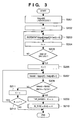
- Fig. 3 is a flow chart showing an example of the processing sequence by the threshold value determination circuit 101.
- a histogram of luminance value is calculated using a value for upper 3 bits of pixel data for one line (steps S201 to S205). Subsequently, a portion where the total value of a histogram including neighboring levels becomes 75% or more the total number of pixels for one line is detected, and it is determined that the luminance indicated by that histogram is the background of an original (steps S206 to S208, S211, and S212).
- an edge detection threshold value (THR_MAXMIN) to be passed to the edge detection circuit 102, and a binarization threshold value (BI_THRE) to be passed to the binarization circuit 106 are determined (steps S209 and S210).
- TRR_MAXMIN edge detection threshold value
- BI_THRE binarization threshold value
- step S201 a histogram buffer histgnd[8] is reset to 0. That is, "0" is written in all eight histogram buffers histgnd[0] to histgnd[7].
- step S202 a pixel counter i is reset to 0. The pixel counter i is used for discriminating whether or not pixels for one line have been processed, upon generating a histogram of pixel data for one line.
- step S203 i-th pixel data image[i] is shifted to the right by five bits (to leave upper 3 bits alone of pixel data), and the histogram buffer histgnd [] corresponding to that 3 bits value is incremented.
- step S204 the pixel counter i is incremented. It is checked in step S205 if processing for one line has ended. If YES in step S205, the flow advances to step S206; otherwise, the flow returns to step S203.
- steps S203 to S205 By repeating steps S203 to S205 above, pixel data for one line are distributed to one of levels histgnd[0] to histgnd[7], and the values are stored in histgnd[0] to histgnd[7]. That is, a histogram for upper 3 bits for 1-line data can be obtained.
- the binarization threshold value (BI_THRE) and edge detection threshold value (THR_MAXMIN) are determined.
- step S206 K indicating a histogram level number is reset to 3. Histogram values having neighboring K-th and (K+1)-th levels are added to each other in step S207, and it is checked in step S208 if the sum exceeds 75% the number of pixels for one line.
- the reason why the value K is reset to not 0 but 3 lies in the following fact. That is, even when background level (0 to 2) near black level of the histogram is detected, characters are unlikely to be present on such background. Also, even when characters are present, they are likely to be outlined characters. Hence, levels 0 to 2 are excluded from the discrimination range. Note that outlined character processing (e.g., reversal upon binarization) may be done.
- step S208 it is checked in step S208 if the histadd obtained in step S207 exceeds 75% the total number of pixels in one line. If YES in step S208, it is determined that the level of interest indicates background, and the flow advances to step S209 to determine the threshold value. On the other hand, if NO in step S208, the flow advances to step S211 to increment K by 1 and to check for the next level.
- step S209 the value obtained by shifting K to the left by five bits is substituted in THR_MAXMIN as the edge detection threshold value.
- the lower limit value of the pixel value range that histgnd[K] covers is set in the edge detection threshold value.
- step S210 the value obtained by shifting (K+1) to the left by four bits is substituted in the binarization threshold value BI_THRE, thus ending the processing.
- a value 1/2 the lower limit value of the pixel value range that histgnd[K+1] covers is set in the binarization threshold value.
- K is incremented in step S211. If it is determined in step S212 that K ⁇ 7, the flow returns to step S207 to repeat the above-mentioned processing. On the other hand, if K > 7, this processing ends. As a result, the previous edge detection threshold value and binarization threshold value are held.
- threshold value determination circuit 101 By providing such threshold value determination circuit 101 to vary THR_MAXMIN, even characters printed on color paper can be satisfactorily extracted.
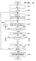
- Figs. 4 to 6 are flow charts for explaining the processing sequence of the edge detection circuit. Note that the processing of the threshold value determination circuit 101 described above with reference to Fig. 3, and the processing of the edge detection circuit 102 shown in Figs. 4 to 6 are simultaneously executed, and the edge detection threshold value THR_MAXMIN in Fig. 3 is constantly changing. In this case, the determined threshold value is applied to the processing for the next line.
- edge detection circuit 102 In edge detection, continuous SAMPLE_PIXEL pixels are extracted from one line, and it is checked based on the difference between the maximum and minimum values of the extracted pixels if the extracted portion corresponds to an edge portion (steps S301 to S308). Based on this discrimination result, detection of the start and end positions of an edge, coupling of neighboring edges, counting of the number of edges, and the like are done (steps S311 to S317, and S321 to S326). The aforementioned processing is executed for one line while overlapping the pixel extraction range by SAMPLE_PIXEL/2 pixels, and the obtained edge information is written in the edge coordinate memory (steps S309, S310, and S330).
- edge detection is executed for the 0th to 7th pixels, for the 4th to 11th pixels, then for the 8th to 15th pixels, and so forth, while overlapping the pixel extraction range. Edge detection will be described in detail below with reference to Figs. 4 to 6.
- step S301 index i counting the number of pixels per line, and index count counting the number of extracted edges are reset to zero.
- a flag "flag” indicating if edge extraction is in progress is reset to OFF.
- step S303 "0" is set in maxdata, and "255” is set in mindata.
- steps S304 to S306 SAMPLE_PIXEL pixels starting from the i-th pixel are checked, the maximum value of these pixels is stored in maxdata, and the minimum value is stored in mindata.
- step S307 the difference between the maximum and minimum values maxdata and mindata is substituted in diff.
- step S308 It is checked in step S308 if diff is larger than THR_MAXMIN determined by the threshold value determination circuit 101. If diff > THR_MAXMIN, the flow advances to node A (step S311 in Fig. 5); otherwise, the flow advances to node B (step S321 in Fig. 6). After the processing in node A or B, the flow returns to node C, and i is incremented by SAMPLE_PIXEL/2 in step S309. It is checked in step S310 if processing for one line has ended. If YES in step S310, edge information is written in the edge coordinate memory 103 in step S330, thus ending this processing. On the other hand, if NO in step S310, the flow returns to step S303 to repeat the above-mentioned processing.
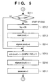
- step S308 If it is determined in step S308 that diff > THR_MAXMIN, the flow advances to step S311 in Fig. 5.
- step S311 It is checked in step S311 if the flag "flag" indicating whether or not edge extraction is in progress is OFF. If flag is OFF, the start of an edge is determined, and the flow advances to step S312 to execute edge start processing (steps S312 to S314). On the other hand, if flag is ON, since edge extraction is in progress, the flow jumps to step S315 without executing edge start processing.
- step S312 the flag "flag" indicating whether or not edge extraction is in progress is set ON in step S312.
- step S313 i is substituted in startx[count] indicating the start coordinate of the edge of interest ((count)-th edge).
- start coordinate of the (count)-th edge is set at the head pixel of THE SAMPLE_PIXEL pixels of interest.
- edgenum[count] indicating the number of edges of the edge of interest ((count)-th edge) is reset to zero in step S314.
- step S315 i + SAMPLE_PIXEL/2 is substituted in endx[count] indicating the end coordinate of the (count)-th edge.
- step S316 edgenum[count] indicating the number of edges of the (count)-th edge is incremented.
- step S317 space_count for counting the number of spaces in the horizontal direction is reset to zero. This space_count is used for determining an identical edge (i.e., to couple neighboring edge portions in the horizontal direction) if the number of spaces is equal to or smaller than a threshold value, even when a small region without any edge is present in the horizontal direction, in the processing in steps S321 to S326 to be described later. This processing reduces the load on coupling processing to be described later.
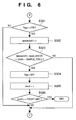
- step S308 in Fig 4 determines whether diff ⁇ THR_MAXMIN. If it is determined in step S308 in Fig 4 that diff ⁇ THR_MAXMIN, the flow advances to step S321 in Fig. 6.
- step S321 It is checked in step S321 if the flag "flag" indicating whether or not edge extraction is in progress is ON. If YES in step S321, since the edge may have ended, the flow advances to step S322. On the other hand, if flag is OFF, the flow directly jumps to node C (step S309). In step S322, space_count is incremented. It is checked in step S323 if space_count is equal to or larger than predetermined space_limit, or if i is larger than (horizontal width "width" of image - SAMPLE_PIXEL). If one of these conditions is met, the flow advances to step S324. However, if neither of these conditions are met, the flow directly jumps to node C (step S309).
- the former condition in step S323 determines the end of the edge of interest if the number of small regions without any edge exceeds the limit value (space_limit). This condition implements coupling of edge portions.
- the latter condition indicates a case wherein processing for the raster image width (width) is finished, and the edge of interest must be ended.
- step S323 If the end of the edge is determined in step S323, the flag "flag” indicating whether or not edge extraction is in progress is set OFF in step S324. In step S325, count indicating the number of edges is incremented. It is checked in step S326 if count has reached COUNT_LIMIT. If YES in step S326, the flow advances to node "END" to prevent the memory area of the edge coordinate memory 103 from overflowing. If NO in step S326, the flow advances to node C (step S309).
- Fig. 7 is a view for explaining an example of the overlapping ranges in edge detection.
- SAMPLE_PIXEL 8
- the 0th to 7th pixels are checked to obtain their maximum and minimum values, and steps S307 to S310 are then executed.
- the 4th to 11th pixels are checked to obtain their maximum and minimum values, and steps S307 to S310 are then executed.
- the 8th to 15th pixels are checked to obtain their maximum and minimum values, and steps S307 to S310 are then executed. In this way, processing is executed while extracting pixels from overlapping ranges.
- ⁇ indicates a case wherein diff > THR_MAXMIN in a small region including the processed SAMPLE_PIXEL pixels
- X indicates a case wherein diff ⁇ THR_MAXMIN.
- edgenum[0] is reset to zero in step S314, it is incremented to 1 in step S316 after that.
- step S308 since diff > THR_MAXMIN again, the flow advances from step S308 to step S311. Since flag is ON in step S311, the flow branches to NO to substitute 28 in endx[0], to increment edgenum[0] to 3, and to reset space_count to zero.
- edge extraction in the horizontal direction is executed while coupling neighboring edges spaced by a given distance or less.
- Fig. 9 is a flow chart showing an example of the processing sequence of the coupling processing circuit 106.
- the coupling processing circuit 106 executes coupling processing, fix processing, band processing, and the like on the basis of new edge information stored in the edge coordinate memory 103 and region information stored in the region information memory 104 to update the region information in turn.
- Region information stored in the region information memory 104 will be explained below.
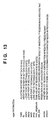
- Fig. 13 shows an example of region information stored in the region information memory 104.
- valid is 1-bit information indicating whether or not the region information is valid.
- fix is 1-bit information indicating whether or not the region information is fixed.
- endx is the x-axis end point of rectangle data.
- This data can be expressed by 9 bits if the maximum original size is A3 and the number of samples in edge detection is 8. endy is the y-axis end point of rectangle data. This data can be expressed by 11 bits if the maximum original size is A3 and the processing spacing of edge detection is 4.
- max_edgenum is the edge amount of rectangle data in a band. For example, if max_edgenum holds the maximum number of edges determined by a MAXMIN threshold value, this data can be expressed by 9 bits since it does not exceed the maximum value of X.
- pre_del is 1-bit information indicating whether or not that rectangle data is determined not to be a character in character discrimination of the immediately preceding band.
- series is 1-bit information indicating whether or not that rectangle data continues from the immediately preceding band.
- remain is 1-bit information indicating whether or not that rectangle data is determined to be a character in character discrimination of previous bands.
- step S601 coupling processing of edge coordinate data (edge start point startx[], edge end point endx[]) detected by the edge detection circuit 102 and stored in the edge coordinate memory 103, and region information stored in the region information memory 104 is performed.
- Figs. 10A and 10B are views for explaining the coupling processing.
- Reference numerals 701 to 704 and 712 in Fig. 10A denote examples of regions indicated by region information stored in the region information memory 104.
- reference numerals 705 to 708 and 713 are examples of edge portions indicated by edge information detected by the edge detection circuit 102 and stored in the edge coordinate memory 103.
- information stored in the region information memory 104 includes the rectangle start coordinate data (startx, starty), the rectangle end coordinate data (endx, endy), the maximum number of edges (max_edgenum), and the flag (fix) indicating whether or not that rectangle is fixed.
- the format of the region information is not limited to the above-mentioned example, and each region needs not have a rectangular shape.
- the edge information stored in the edge coordinate memory 104 includes the start point (startx), end point (endx), and the number of edges (edge_num).
- the coupling processing circuit 105 determines based on the positional relationship between the region 701 stored in the region information memory 104 and the edge region 705 stored in the edge coordinate memory 103 that they are to be coupled, generates region information of a region 709 as a result, and overwrites the region information of the region 701 in the region information memory 104 with the region information of the region 709.
- the maximum number of edges is a larger one of max_edgenum of the region 701, and edge_num of the edge region 705.
- the rectangle start coordinate data (startx, starty), rectangle end coordinate data (endx, endy), and the maximum number of edges (max_edgenum) associated with the region 701 are updated to obtain region information indicating the rectangle 709 in Fig. 10B.
- Whether or not a region stored in the region information memory 104 is coupled to an edge region stored in the edge information memory is determined by checking if the x-coordinates of these two regions overlap each other, and the minimum spacing between the y-coordinates of the two regions is equal to or smaller than space_limit_h. If these conditions are met, coupling is done.
- the circuit 105 determines that the edge regions 706 and 707 are to be coupled to the region 702, generates region information of a region 710 as a result, and overwrites the region information of the region 702 in the region information memory with the generated region information.
- the maximum number of edges is a larger one of max_edgenum of the region 702 and the sum of values edge_num of the edge regions 706 and 707.
- edge region 708 Since the edge region 708 is coupled to both the regions 703 and 704, region information of a region 711 is generated as a result. The generated region information is overwritten on the that of the region 703 in the region information memory 104, and that of the region 704 is deleted. In this case, the maximum number of edges is a larger one of the sum of values max_edgenum of the regions 703 and 704, and edge_num of the edge region 708.
- region information of a closed rectangle is extracted and is fixed in step S602. Fix processing will be explained below with the aid of Figs. 10A and 10B. Since the region 712 stored in the region information memory 104 has no edge region to be coupled within the range space_limit_h below it, it is determined that the rectangle of this region information is closed, and fix processing is done. In the fix processing, it is checked if the region of interest is a character region.
- space_limit determines whether or not neighboring edges which are slightly separated from each other in the horizontal direction are coupled
- space_limit_h is used for determining whether or not neighboring edges which are slightly separated from each other in the vertical direction are coupled.
- step S603 it is checked in step S603 if band processing is to be executed.
- the band processing is done in response to a multiple of 64 pixels (64 lines) in the ordinate direction as a trigger.
- the flow advances to step S604 every 64th line to execute band processing. If the band processing timing is not reached, the processing of the line of interest ends.
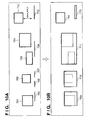
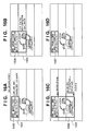
- Figs. 11A to 11D are views for explaining the principle of the band processing.
- Fig. 11A shows an original to be processed.
- Fig. 11B shows an image divided into bands by the band processing.
- Fig. 11C shows character regions of the image shown in Fig. 11A. Portions bounded by bold rectangles are extracted character regions.
- Fig. 11D shows the image held in the real memory space of the binary memory. A band including no characters is temporarily written in the memory but is overwritten by a new band if it is determined that no characters are present in the band. As a result, the image shown in Fig. 11A is stored in the memory while omitting bands including no characters.
- eight bands can be stored in a real image space, and can also be stored in the memory space.
- the number of bands to be stored in the memory space is set to be smaller than that in the real image space. For example, the number of bands in the real image space is 64, and that in the memory space is 16.
- Figs. 12A and 12B are views for explaining information pertaining to the bands of an image and those in the memory.
- Fig. 12B shows information indicating the number of character regions in each band of the memory. This information is named region_in_band[]. If Fig. 11D shows the storage result in the memory, final region_in_band[8] is ⁇ 2, 1, 1, 1, 1, 0, 0, 0 ⁇ . For example, the uppermost band includes two character regions.
- the aforementioned information mem_no_for_band[] and information region_in_band[] are generated by the band memory controller 11, and are used to generate the address of the binary memory. This processing will be explained in detail later.
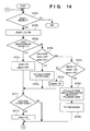
- Fig. 14 is a flow chart for explaining the sequence of the band processing. It is checked in step S701 if the band of interest includes rectangular regions obtained by the coupling processing or the like. If YES in step S701, the flow advances to step S702 to select one region.
- step S703 It is checked in step S703 if the selected region includes characters in the band of interest. This checking may be attained by various methods. For example, the same conditions as those in step S602 may be used. If it is determined in step S703 that the region includes characters, the flow advances to step S704; otherwise, the flow advances to step S705.
- step S704 remain of the region information is set ON, and pre_del OFF.
- step S707 If the condition in step S707 is not satisfied, either, the flow advances to step S710 to set pre_del ON, and the flow then advances to step S711.
- step S711 It is checked in step S711 if the rectangular region of interest continues to the next band. If YES in step S711, series in the region information of the rectangular region of interest is set ON in step S712. The flow then returns to step S701 to process the next rectangular region. If no rectangular regions to be processed remain in step S701, this processing ends.
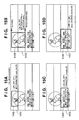
- Figs. 15A to 15D and Figs. 16A to 16D are views for explaining examples of the band processing.
- FIG. 15A shows the processing of an uppermost band 1401.
- a rectangle 1402 has been extracted by edge detection and coupling processing.
- (pre_del, series, remain) is (OFF, OFF, OFF) since this rectangle starts within that band.
- max_edgenum indicating the edge amount in that rectangle information is very small since this rectangle includes the illustration, and does not exceed the threshold value for character discrimination.
- the character discrimination result of the rectangle 1402 in the band 1401 is "not character", and since the rectangular region of interest continues to the next band, rectangle information (pre_del, series, remain) is (ON, ON, OFF).
- Fig. 15B shows the processing of a second band 1403.
- a rectangle 1404 has been extracted.
- Its rectangle information pre_del, series, remain) is (ON, ON, OFF) in accordance with the band processing result of the band 1401.
- max_edgenum indicating the edge amount in that rectangle information is very small owing to the presence of the illustration, and does not exceed the threshold value for character discrimination.
- the character discrimination result of the rectangle 1404 in the band 1403 is "not character".
- step S706 processing for moving down starty (step S706) is executed.
- starty saved in the rectangle information indicates a point present in the band 1401.
- Fig. 15C shows the processing of a third band 1405.
- a rectangle 1406 has been extracted.
- Its rectangle information (pre_del, series, remain) is (ON, ON, OFF) in accordance with the band processing result of the band 1403.
- max_edgenum indicating the edge amount in that rectangle information is very large owing to the presence of characters and exceeds the threshold value for character discrimination.
- the character discrimination result of the rectangle 1406 in the band 1405 is "character”
- the rectangle information (pre_del, series, remain) is updated to (OFF, ON, ON).
- Fig. 15D shows the state wherein a rectangle is closed within a fourth band 1407.
- a rectangle 1408 is extracted, and is closed (does not continue any more).
- its rectangle information pre_del, series, remain
- max_edgenum indicating the edge amount in that rectangle information is very large owing to the presence of characters and exceeds the threshold value for character discrimination.
- the character discrimination result of the closed rectangle 1408 in the band 1407 is "character”.
- that rectangle is held as a character rectangle.
- Fig. 16A shows the processing of an uppermost band 1501.
- a rectangle 1502 has been extracted by edge detection and coupling processing. Since this rectangle starts in that band, its rectangle information (pre_del, series, remain) is (OFF, OFF, OFF).
- max_edgenum indicating the edge amount in the rectangle information is very large due to the presence of a character portion, and exceeds the threshold value for character discrimination.
- the character discrimination result in the rectangle 1502 in the band 1501 is "character”
- rectangle information (pre_del, series, remain) is updated to (OFF, ON, ON).
- Fig. 16B shows the processing of a second band 1503.
- a rectangle 1504 has been extracted.
- Its rectangle information (pre_del, series, remain) is (OFF, ON, ON) in accordance with the band processing result of the band 1501.
- max_edgenum indicating the edge amount in the rectangle information is very small due to the presence of an illustration portion, and does not exceed the threshold value for character discrimination.
- the character discrimination result of the rectangle 1504 in the band 1503 is "not character”.
- the rectangle information (pre_del, series, remain) is updated to (ON, ON, ON).
- Fig. 16C shows the processing of a third band 1505.
- a rectangle 1506 has been extracted.
- Its rectangle information (pre_del, series, remain) is (ON, ON, ON) in accordance with the band processing result of the band 1503.
- max_edgenum indicating the edge amount in the rectangle 1506 in the band 1505 is very small due to the presence of an illustration portion, and does not exceed the threshold value for character discrimination.
- the character discrimination result of the rectangle 1506 in the band 1505 is "not character”.
- pre_del, series, and remain are respectively ON, ON, and ON, processing for moving up endy and closing the rectangle is done.
- endy saved in the current rectangle information indicates the final line of the band 1505.
- Fig. 16D shows the state of a finally obtained character rectangle 1507.
- a new rectangle is generated by coupling processing in the next band.
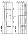
- Figs. 17A and 17B are views for explaining changes in the number of rectangles as a result of coupling processing.
- the number of rectangles changes by the coupling processing.
- rectangles cease to exist in the bands 1401 and 1403.
- the control is made to overwrite a new next band on these bands.
- the number of rectangles region_in_band[] of each of the bands 1503 and 1505 becomes zero, and these bands are overwritten by another band.
- bands including no characters are efficiently removed, thus reducing the memory capacity of the binary memory.
- region_in_band[mem_no_for_band[5]] change as follows:
- Fig. 18 is a flow chart for explaining the processing sequence of the band memory controller 111.
- step S811 zero is substituted in variable m that represents the band number to be processed.
- step S812 "0" is substituted in mem_no_for_band[0] and "1" in mem_no_for_band [1]. That is, the first two bands of image data are stored in the 0th and 1st bands in the memory space.
- step S813 the address of the binary memory 107 is controlled to begin to write binary data of the m-th band of the image data in (mem_no_for_band[m])-th band.
- step S814 the numbers of rectangles of the bands already stored in the binary memory, i.e., the number of rectangles stored in region_in_band[mem_no_for_band[0]] to region_in_band [mem_no_for_band[m-1]] are updated. In this case, the processing results of the aforementioned coupling processing and band processing are reflected.
- step S818 variable m is incremented to start processing of the next band of the image data (the flow returns to step S813 via step S819). If the processing for all the bands in the image data is complete, this processing ends (step S819).
- character extraction can be satisfactorily attained without requiring any buffer.
- character recognition for discriminating the original direction is started.
- the contents of the binary memory are accessed using the region information stored in the region information memory 104 to acquire a character region image.
- the binary memory stores image data in units of bands, and its order is managed by mem_no_for_band[].
- the CPU 108 informs the band memory controller 111 of the required region, and the band memory controller 111 sends back the corresponding region data in the binary memory 107 to the CPU 108.
- edge detection circuit 102 Since the aforementioned processing of the edge detection circuit 102 is done in units of, e.g., four input lines, and the coupling processing between the contents of the edge coordinate memory 103 and region information memory 104 by the coupling processing circuit 105 is done in the remaining three lines, real-time processing can be realized without stopping input pixels in units of lines. When processing cannot be completed within the time for three lines, double region information memories may be used to assure a time for four lines. Also, numeral "4" is an example, but may be "5", "6", “8", or "16".
- Fig. 19 is a timing chart when the character extraction described above is used in direction recognition.
- reference numeral 801 denotes an image input from a scanner (CCD); 802, binarization of a multi-valued image input from the scanner.
- Reference numeral 803 denotes character extraction by the aforementioned character extraction unit 1A. That is, character extraction is executed in real time in synchronism with the input from the scanner.
- Reference numeral 804 denotes OCR processing, which is done in four directions for a character region extracted by the character extraction 803 to discriminate the direction of a document, vertical or horizontal writing, and the like.
- the OCR processing 804 discriminates within a predetermined period of time using a timer, and if discrimination fails, it returns zero degree of confidence as UNKNOWN.
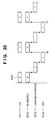
- Fig. 20 is a timing chart for explaining the timing of conventional character direction discrimination. Although original reading by the CCD and binarization progress in real time, character region extraction and direction discrimination by means of OCR are started after an image for one page has been read.
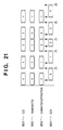
- the binary memory 107 includes two memories.
- the processing can be done at the timing shown in Fig. 21. That is, immediately after a character region is extracted by character extraction 903, OCR processing is started. In such case, the CCD must often be stopped. However, the processing time may be limited using a timer as in Fig. 19, and if direction discrimination fails within the limited time, UNKNOWN may be returned. In such case, the CCD need not be stopped. As shown in an example for the second page, the direction may be discriminated before the beginning of the next page.
- a high-frequency region is detected by checking only the horizontal direction of a raster image.
- the present invention is not limited to such specific method, but a high-frequency region may be detected two-dimensionally.
- a register for holding maximum and minimum values for the number of horizontal pixels of an image/SAMPLE_PIXEL (horizontal) is required.
- the difference between the maximum and minimum value is used in edge detection.
- a high-frequency portion may be detected by frequency conversion.
- a region in which the number of detected edges is equal to or larger than a predetermined value is detected as a character region.
- a region in which the number of detected edges is equal to or smaller than a predetermined value may be detected as a picture region.
- a character region can be extracted in real time in units of lines in place of pages without stopping the CCD.
- the present invention may be applied to either a system constituted by a plurality of equipments (e.g., a host computer, interface device, reader, printer, and the like), or an apparatus consisting of a single equipment (e.g., a copying machine, facsimile apparatus, or the like).
- equipments e.g., a host computer, interface device, reader, printer, and the like
- apparatus consisting of a single equipment e.g., a copying machine, facsimile apparatus, or the like.
- the objects of the present invention are also achieved by supplying a storage medium, which records a program code of a software program that can realize the functions of the above-mentioned embodiments to the system or apparatus, and reading out and executing the program code stored in the storage medium by a computer (or a CPU or MPU) of the system or apparatus.
- the program code itself read out from the storage medium realizes the functions of the above-mentioned embodiments, and the storage medium which stores the program code constitutes the present invention.
- the storage medium for supplying the program code for example, a floppy disk, hard disk, optical disk, magneto-optical disk, CD-ROM, CD-R, magnetic tape, nonvolatile memory card, ROM, and the like may be used.
- the functions of the above-mentioned embodiments may be realized not only by executing the readout program code by the computer but also by some or all of actual processing operations executed by an OS (operating system) running on the computer on the basis of an instruction of the program code.
- OS operating system
- the functions of the above-mentioned embodiments may be realized by some or all of actual processing operations executed by a CPU or the like arranged in a function extension board or a function extension unit, which is inserted in or connected to the computer, after the program code read out from the storage medium is written in a memory of the extension board or unit.
- a specific image region can be extracted from an image signal at high speed using a small memory capacity without waiting for completion of storage of the entire image signal in a memory and without storing an unnecessary image region in a memory.
Landscapes
- Engineering & Computer Science (AREA)
- Multimedia (AREA)
- Signal Processing (AREA)
- Image Analysis (AREA)
- Character Input (AREA)
- Storing Facsimile Image Data (AREA)
- Facsimile Image Signal Circuits (AREA)
Applications Claiming Priority (3)
| Application Number | Priority Date | Filing Date | Title |
|---|---|---|---|
| JP317453/97 | 1997-11-18 | ||
| JP31745397 | 1997-11-18 | ||
| JP31745397A JP3884845B2 (ja) | 1997-11-18 | 1997-11-18 | 情報処理装置及び方法 |
Publications (3)
| Publication Number | Publication Date |
|---|---|
| EP0917349A2 EP0917349A2 (en) | 1999-05-19 |
| EP0917349A3 EP0917349A3 (en) | 2000-03-22 |
| EP0917349B1 true EP0917349B1 (en) | 2006-10-04 |
Family
ID=18088402
Family Applications (1)
| Application Number | Title | Priority Date | Filing Date |
|---|---|---|---|
| EP98309325A Expired - Lifetime EP0917349B1 (en) | 1997-11-18 | 1998-11-13 | Document image data processing for detecting, extracting and coupling of regions with same characteristics |
Country Status (4)
| Country | Link |
|---|---|
| US (1) | US6175662B1 (enExample) |
| EP (1) | EP0917349B1 (enExample) |
| JP (1) | JP3884845B2 (enExample) |
| DE (1) | DE69836065T2 (enExample) |
Families Citing this family (9)
| Publication number | Priority date | Publication date | Assignee | Title |
|---|---|---|---|---|
| US6778297B1 (en) * | 1999-04-12 | 2004-08-17 | Minolta Co., Ltd. | Image processing apparatus, method, and computer program product |
| JP4920814B2 (ja) * | 2000-04-27 | 2012-04-18 | キヤノン株式会社 | 画像処理方法、装置および記録媒体 |
| JP4558232B2 (ja) * | 2001-03-26 | 2010-10-06 | 株式会社リコー | 画像処理方法、画像処理装置および画像処理方法をコンピュータに実行させるプログラムを記録したコンピュータ読み取り可能な記録媒体 |
| JP4078132B2 (ja) | 2002-06-28 | 2008-04-23 | キヤノン株式会社 | 画像処理装置及びその方法 |
| US7486297B2 (en) * | 2003-09-22 | 2009-02-03 | Ati Technologies, Inc. | Method and apparatus for image processing in a handheld device |
| US7822277B2 (en) | 2005-08-31 | 2010-10-26 | Ati Technologies Ulc | Method and apparatus for communicating compressed video information |
| JP4626598B2 (ja) * | 2006-09-28 | 2011-02-09 | ブラザー工業株式会社 | 画像読取装置、複写装置及び画像読取方法 |
| JP4577421B2 (ja) * | 2008-07-10 | 2010-11-10 | 富士ゼロックス株式会社 | 画像処理装置及び画像処理プログラム |
| JP5888068B2 (ja) * | 2012-03-30 | 2016-03-16 | ブラザー工業株式会社 | 画像処理装置およびプログラム |
Family Cites Families (5)
| Publication number | Priority date | Publication date | Assignee | Title |
|---|---|---|---|---|
| US5077811A (en) | 1990-10-10 | 1991-12-31 | Fuji Xerox Co., Ltd. | Character and picture image data processing system |
| JP3630705B2 (ja) | 1993-08-02 | 2005-03-23 | コニカミノルタビジネステクノロジーズ株式会社 | デジタル複写装置 |
| US5987171A (en) | 1994-11-10 | 1999-11-16 | Canon Kabushiki Kaisha | Page analysis system |
| JP3727971B2 (ja) | 1995-02-01 | 2005-12-21 | キヤノン株式会社 | 文書処理装置、及び文書処理方法 |
| US5978519A (en) * | 1996-08-06 | 1999-11-02 | Xerox Corporation | Automatic image cropping |
-
1997
- 1997-11-18 JP JP31745397A patent/JP3884845B2/ja not_active Expired - Fee Related
-
1998
- 1998-11-13 EP EP98309325A patent/EP0917349B1/en not_active Expired - Lifetime
- 1998-11-13 DE DE69836065T patent/DE69836065T2/de not_active Expired - Lifetime
- 1998-11-13 US US09/191,533 patent/US6175662B1/en not_active Expired - Fee Related
Also Published As
| Publication number | Publication date |
|---|---|
| EP0917349A2 (en) | 1999-05-19 |
| JPH11150655A (ja) | 1999-06-02 |
| JP3884845B2 (ja) | 2007-02-21 |
| EP0917349A3 (en) | 2000-03-22 |
| DE69836065T2 (de) | 2007-02-22 |
| US6175662B1 (en) | 2001-01-16 |
| DE69836065D1 (de) | 2006-11-16 |
Similar Documents
| Publication | Publication Date | Title |
|---|---|---|
| EP0081767B1 (en) | Character and image processing apparatus | |
| US5677776A (en) | Image reader for processing an image of a document | |
| US4631596A (en) | Image communications apparatus for long-size copy image | |
| US6072941A (en) | Image processing apparatus and method which classifies images according to attributes | |
| JP3123609B2 (ja) | 自動規準化、自動用紙選択、及び窓規準化を備えた複写機 | |
| US6289121B1 (en) | Method and system for automatically inputting text image | |
| JP4586241B2 (ja) | 画像処理装置 | |
| JPH07221969A (ja) | 画像形成装置 | |
| EP0917349B1 (en) | Document image data processing for detecting, extracting and coupling of regions with same characteristics | |
| US6690492B2 (en) | Image processing method and apparatus | |
| US5140440A (en) | Method of detecting a processing area of a document for an image forming apparatus | |
| JP3684036B2 (ja) | 画像処理装置及び画像処理方法 | |
| US5195147A (en) | Image forming apparatus | |
| US5589948A (en) | Facsimile apparatus | |
| JPH0818764A (ja) | 枠内領域矩形化装置 | |
| US5420694A (en) | Image processing system | |
| US7149371B2 (en) | Image filing apparatus | |
| JP3774502B2 (ja) | 画像処理装置およびその方法 | |
| JP3191265B2 (ja) | 画像入力装置およびその画像入力制御方法 | |
| JPH08305835A (ja) | 画像処理装置およびその方法 | |
| KR940001976B1 (ko) | 팩시밀리 장치의 축소 기록방법 | |
| JP2872757B2 (ja) | 行方向判定装置 | |
| JP2002142070A (ja) | 画像伝送システムおよび画像伝送装置ならびにそれらの方法 | |
| JP3160458B2 (ja) | 文字読取装置及び文字読取方法 | |
| JPH01269179A (ja) | 画像処理装置 |
Legal Events
| Date | Code | Title | Description |
|---|---|---|---|
| PUAI | Public reference made under article 153(3) epc to a published international application that has entered the european phase |
Free format text: ORIGINAL CODE: 0009012 |
|
| AK | Designated contracting states |
Kind code of ref document: A2 Designated state(s): DE FR GB |
|
| AX | Request for extension of the european patent |
Free format text: AL;LT;LV;MK;RO;SI |
|
| PUAL | Search report despatched |
Free format text: ORIGINAL CODE: 0009013 |
|
| AK | Designated contracting states |
Kind code of ref document: A3 Designated state(s): AT BE CH CY DE DK ES FI FR GB GR IE IT LI LU MC NL PT SE |
|
| AX | Request for extension of the european patent |
Free format text: AL;LT;LV;MK;RO;SI |
|
| RIC1 | Information provided on ipc code assigned before grant |
Free format text: 7H 04N 1/40 A, 7H 04N 1/00 B |
|
| 17P | Request for examination filed |
Effective date: 20000802 |
|
| AKX | Designation fees paid |
Free format text: DE FR GB |
|
| 17Q | First examination report despatched |
Effective date: 20030718 |
|
| GRAP | Despatch of communication of intention to grant a patent |
Free format text: ORIGINAL CODE: EPIDOSNIGR1 |
|
| RTI1 | Title (correction) |
Free format text: DOCUMENT IMAGE DATA PROCESSING FOR DETECTING, EXTRACTING AND COUPLING OF REGIONS WITH SAME CHARACTERISTICS |
|
| GRAS | Grant fee paid |
Free format text: ORIGINAL CODE: EPIDOSNIGR3 |
|
| GRAA | (expected) grant |
Free format text: ORIGINAL CODE: 0009210 |
|
| AK | Designated contracting states |
Kind code of ref document: B1 Designated state(s): DE FR GB |
|
| REG | Reference to a national code |
Ref country code: GB Ref legal event code: FG4D |
|
| REF | Corresponds to: |
Ref document number: 69836065 Country of ref document: DE Date of ref document: 20061116 Kind code of ref document: P |
|
| ET | Fr: translation filed | ||
| PLBE | No opposition filed within time limit |
Free format text: ORIGINAL CODE: 0009261 |
|
| STAA | Information on the status of an ep patent application or granted ep patent |
Free format text: STATUS: NO OPPOSITION FILED WITHIN TIME LIMIT |
|
| 26N | No opposition filed |
Effective date: 20070705 |
|
| PGFP | Annual fee paid to national office [announced via postgrant information from national office to epo] |
Ref country code: DE Payment date: 20101130 Year of fee payment: 13 |
|
| PGFP | Annual fee paid to national office [announced via postgrant information from national office to epo] |
Ref country code: GB Payment date: 20101126 Year of fee payment: 13 |
|
| PGFP | Annual fee paid to national office [announced via postgrant information from national office to epo] |
Ref country code: FR Payment date: 20111212 Year of fee payment: 14 |
|
| GBPC | Gb: european patent ceased through non-payment of renewal fee |
Effective date: 20121113 |
|
| REG | Reference to a national code |
Ref country code: FR Ref legal event code: ST Effective date: 20130731 |
|
| REG | Reference to a national code |
Ref country code: DE Ref legal event code: R119 Ref document number: 69836065 Country of ref document: DE Effective date: 20130601 |
|
| PG25 | Lapsed in a contracting state [announced via postgrant information from national office to epo] |
Ref country code: DE Free format text: LAPSE BECAUSE OF NON-PAYMENT OF DUE FEES Effective date: 20130601 |
|
| PG25 | Lapsed in a contracting state [announced via postgrant information from national office to epo] |
Ref country code: GB Free format text: LAPSE BECAUSE OF NON-PAYMENT OF DUE FEES Effective date: 20121113 Ref country code: FR Free format text: LAPSE BECAUSE OF NON-PAYMENT OF DUE FEES Effective date: 20121130 |