EP0916592B1 - Pallet container with grid support structure - Google Patents
Pallet container with grid support structure Download PDFInfo
- Publication number
- EP0916592B1 EP0916592B1 EP97119264A EP97119264A EP0916592B1 EP 0916592 B1 EP0916592 B1 EP 0916592B1 EP 97119264 A EP97119264 A EP 97119264A EP 97119264 A EP97119264 A EP 97119264A EP 0916592 B1 EP0916592 B1 EP 0916592B1
- Authority
- EP
- European Patent Office
- Prior art keywords
- elements
- container
- elongate
- positions
- ridges
- Prior art date
- Legal status (The legal status is an assumption and is not a legal conclusion. Google has not performed a legal analysis and makes no representation as to the accuracy of the status listed.)
- Expired - Lifetime
Links
Images


Classifications
-
- B—PERFORMING OPERATIONS; TRANSPORTING
- B23—MACHINE TOOLS; METAL-WORKING NOT OTHERWISE PROVIDED FOR
- B23K—SOLDERING OR UNSOLDERING; WELDING; CLADDING OR PLATING BY SOLDERING OR WELDING; CUTTING BY APPLYING HEAT LOCALLY, e.g. FLAME CUTTING; WORKING BY LASER BEAM
- B23K33/00—Specially-profiled edge portions of workpieces for making soldering or welding connections; Filling the seams formed thereby
- B23K33/004—Filling of continuous seams
- B23K33/006—Filling of continuous seams for cylindrical workpieces
-
- B—PERFORMING OPERATIONS; TRANSPORTING
- B65—CONVEYING; PACKING; STORING; HANDLING THIN OR FILAMENTARY MATERIAL
- B65D—CONTAINERS FOR STORAGE OR TRANSPORT OF ARTICLES OR MATERIALS, e.g. BAGS, BARRELS, BOTTLES, BOXES, CANS, CARTONS, CRATES, DRUMS, JARS, TANKS, HOPPERS, FORWARDING CONTAINERS; ACCESSORIES, CLOSURES, OR FITTINGS THEREFOR; PACKAGING ELEMENTS; PACKAGES
- B65D77/00—Packages formed by enclosing articles or materials in preformed containers, e.g. boxes, cartons, sacks or bags
- B65D77/04—Articles or materials enclosed in two or more containers disposed one within another
- B65D77/0446—Articles or materials enclosed in two or more containers disposed one within another the inner and outer containers being rigid or semi-rigid and the outer container being of polygonal cross-section not formed by folding or erecting one or more blanks
- B65D77/0453—Articles or materials enclosed in two or more containers disposed one within another the inner and outer containers being rigid or semi-rigid and the outer container being of polygonal cross-section not formed by folding or erecting one or more blanks the inner container having a polygonal cross-section
- B65D77/0466—Articles or materials enclosed in two or more containers disposed one within another the inner and outer containers being rigid or semi-rigid and the outer container being of polygonal cross-section not formed by folding or erecting one or more blanks the inner container having a polygonal cross-section the containers being mounted on a pallet
Definitions
- the present invention relates pallet container having an inner plastic container suitable for transporting flowable or liquid substances.
- the invention relates to a support structure arranged to enclose and contact the side walls of the inner container.
- Such pallet containers are particularly useful in the storage and transportation of fluids, for example in the chemical, petroleum or food industry.
- a conventional pallet container of the present type is disclosed in the German Patent DE-C 195 11 723.
- the support structure enclosing the inner container comprises a grid of vertical and horizontal metal tubes, which are deformed at their intersection so as to form four contact points at which the tubes are welded to one another.
- the grid support structure of such pallet containers are subject to various mechanical loads, for example a vertical load when such containers are stacked on one another.
- the containers may slide and hit one another or may even be dropped causing high impact loading.
- Such loading of the grid construction, especially at the welded tube intersections can cause breakage of the welds.
- fatigue cracks can arise in the metal tube material adjacent the tube intersection.
- the object of the present invention is to provide a pallet container with an improved connection of the grid elements which allows improved mechanical strength and durability and which allows simple and inexpensive construction of the container.
- the inner dimension of the receiving opening of the first opening is dimensioned with respect to an outer dimension of the second element so as to provide a frictional fit of the two elements.
- the mechanical strength of the interconnection against bending moments in the plane of the grid is increased.
- the support grid structure of the present pallet container will normally having the first and second elongate elements disposed vertically and horizontally with respect to one another.
- the first elements having the receiving hole will be the vertical elements, while the horizontal elements will penetrate therethrough.
- the first elongate elements disposed horizontally, while the second elements would be disposed vertically and penetrate through the horizontal elements.
- the grid support structure also comprises upper and lower rim elements, which extend about the circumference of the support structure.
- the upper and lower ends of the vertical elongate elements preferably form a T-intersection with the upper and lower rim elements.
- the T-intersection is constructed by passing the vertical element into an opening in the rim element, although it does not penetrate through the rim element as do the above grid intersections.
- the T-intersection can be formed by the same means described above for the grid intersections, with the exception that the vertical elements only pass into a portion of the interior of the rim elements.
- the outer support structure 30 is arranged to enclose and support the side walls of the inner container. As can be seen in Figs. 1b and 1c, the support structure encompasses the entire inner container at its side walls and is formed of a grid of first and second elongate elements 1, 2. The elements are connected to one another at intersections 9. The upper and lower ends of the vertical elements 2 are connected to rim elements 40, 50 which also circumvent the container. In the embodiment of Fig. 1b, the lower rim element 50 is interrupted at the point of the discharge opening 14.
- Embodiments of the intersections 9 are shown in Figs. 2 and 3.
- An opening 3 is formed in the first element 1 so as to allow the second element 2 to penetrate therethrough.
- the first element is a tubular member which may be circular in cross-section (Fig. 2) or rectangular (Fig. 3).
- the second element is also tubular and has a diameter d2 which is naturally smaller than the diameter d1 of the first tube.
- the outer diameter d2 of the second element is 20% to 30% smaller than the outer diameter d1 of the first element.
- the diameter of the first tube 1 can be about 22 mm with the diameter of the second tube 2 being 16 mm.
- both the first and second elements could be solid bars, it is preferred that both of the elements be tubular in construction. It is also possible that the first element be an open profile, which will be discussed below.
- the cross-sectional profile of the tubes need not be circular and square as shown in Figs. 2 and 3, but could also be generally oval, square, triangular or even combinations of the above forms.
- the first and second elements 1, 2 are connected to one another at one or more positions in the region of their intersection.
- two connecting positions 4 are located at the outer surface of the second element 2 which lies opposed to the inner surface of the first element 1 (only the top position 4 is shown).
- the elements 1, 2 are metal tubes
- the second tube when properly positioned within the first tube is welded at the positions 4 under sufficient pressure to urge the two sides of the first tube 1 into contact with the outer wall of the second tube 2 under formation of the weld.
- the second tube 2 requires no further processing once purchased from the manufacturer.
- the first tube need only be provided with the receiving hole 3 at the proper orientation and spacing to the form the grid support structure.
- the inner dimension of the receiving opening 3 formed in the first element 1 is preferably sized with respect to the outer dimension d2 of the second element 2 such that there is no play between the receiving opening 3 and the second element 2.
- the second element 2 is then inserted through the opening 3 under the application of force to overcome friction between the outer surface of the second element 2 and the inner defining surfaces of the receiving opening 3. In this manner a non-positive frictional fit is established between the first and second elements 1, 2.
- This construction adds to the mechanical strength of the connection assembly, particularly against bending moments which may arise under load in the plane of the two elements.
- the above described procedure is preferred, however, a frictional fit or form fit of various types may also be used.
- Fig. 4 shows an arrangement of the grid structure in which the first elements 1 are arranged vertically and the second elements 2 are arranged horizontally and penetrate the first vertical elements 1. Although this orientation is preferred, it is also possible to provide the first element 1 in the horizontal position with the second vertical elements penetrating therethrough in horizontal direction as shown in Figs. 1b and 1c.
- the exterior ridges 8 of the second element 2 penetrate the opening 3 as in Fig. 5a.
- the interior of the first element 1 is provided with two inner ridges 5 which oppose one another about the centre axis x.
- the crest of the exterior ridges 8 at the intersection are dimensioned to engage with the crest of the inner ridges 5 to form the connection positions.
- the second tubular elements 2 define tangential planes 10, 20, which also define the tangential inner and outer planes of the grid support structure.
- the contact positions P 1 , P 2 of the ridges with the second element 2 lie at the two tangential planes 10, 20.
- the maximum width of the intersection corresponds to the distance W and represents the effective dimension of the first tube 1 in the z direction.
- the overall width W is only slightly larger than the distance between the tangential planes 10, 20 of the smaller diameter tube 2. This is particularly advantageous for the pallet container in terms of space savings.
- all surfaces at the intersection are smooth or rounded without any projecting edges. This avoids "catching" of two pallet containers during handling, for example when the containers are placed adjacent to one another.
- the intersection for the grid support structure of the present invention can also be constructed as shown in Figs. 8 or 9.
- the first tubular element 1 is provided with three ridges 5 formed in its interior.
- the second element 2 penetrates the receiving opening 3 so as to contact only one of the three inner ridges 5.
- the two elements 1, 2 are connected to one another at only one position, indicated with the reference numeral 4.
- the centre axis y of the smaller diameter element 2 does not intersect the centre axis x of the first tubular element 1.
- the number of ridges contacted by the second tubular element 2 will depend on its diameter and the orientation of the receiving hole for penetration.
- Fig. 8 the number of ridges contacted by the second tubular element 2 will depend on its diameter and the orientation of the receiving hole for penetration.
- the grid support structure 30 comprises an upper rim 40 and a lower rim 50 to which the vertical elements of the grid are connected in a T-intersection.
- the vertical elements can be the first element 1 having the hole 3 for penetration or can also be the second element 2.
- Figs. 12 and 13 show arrangements for connecting the vertical elements to the upper rim element 40. The same type of T-intersection can of course be used for the lower rim element 50.
- the basic principles for forming the T-intersection are the same as those described above for the crossing intersection of the first and second elements.
- the rim element 40 will be of larger dimension and correspond to the first elongate element described above.
- the vertical element indicated by way of example in Fig. 1 with the reference numeral 1, will correspond to the second element described above in the crossing intersections.
- the receiving hole 42 as shown in Fig. 12 is formed such that the vertical element 1 does not penetrate through the rim element 40.
- the opening is already provided by the open side of the U-shaped profile 40 as the rim element.
- the provisions for connecting the two elements as well as the possible forms and shapes of the respective elements are the same as in the crossing intersection described above in conjunction with the Figs. 2 to 11.
- Figs. 12 and 13 show particularly suitable T-connections in which the rim element 40 comprises two inner ridges which contact the vertical element 1 once inserted into the rim element 40.
- the various elements 1, 2, 40, 50 be made of metal tubes and be welded at their connection positions, it is also contemplated that the connections be made by means of a form fit produced by deformation of the respective elements.
- a recess or indentation could be formed with a press into the outer tube 1 at the intersection location 4. The recess would be deep enough to form a matching recess in the outer surface of the inner second element, whereby a form fit interconnection results.
- the second tube 2 could be deformed either on the interior of the receiving hole 3 or outside of it.
- the second tube 2 could be provided with indentations which match the position of the inner ridges of the first tube 1. Engagement of the ridges in the indentations would produce a fit which would prevent axial movement of the second tube with respect to the first tube.
Abstract
Description
- The present invention relates pallet container having an inner plastic container suitable for transporting flowable or liquid substances. In particular, the invention relates to a support structure arranged to enclose and contact the side walls of the inner container. Such pallet containers are particularly useful in the storage and transportation of fluids, for example in the chemical, petroleum or food industry.
- A conventional pallet container of the present type is disclosed in the German Patent DE-C 195 11 723. The support structure enclosing the inner container comprises a grid of vertical and horizontal metal tubes, which are deformed at their intersection so as to form four contact points at which the tubes are welded to one another.
- In practice, the grid support structure of such pallet containers are subject to various mechanical loads, for example a vertical load when such containers are stacked on one another. In addition, during handling and transportation, the containers may slide and hit one another or may even be dropped causing high impact loading. Such loading of the grid construction, especially at the welded tube intersections can cause breakage of the welds. In addition, with repeated mechanical stress loading at the welds, fatigue cracks can arise in the metal tube material adjacent the tube intersection.
- The object of the present invention is to provide a pallet container with an improved connection of the grid elements which allows improved mechanical strength and durability and which allows simple and inexpensive construction of the container.
- According to the present invention as defined by
claim 1, the inner plastic container for transporting liquids is supported by a grid structure arranged to enclose and contact the side walls of the inner container. The grid of the support structure comprises first and second elongate elements crossing one another at intersections. Each first elongate element is provided with a receiving opening through which the respective second elongate element passes and penetrates through the first element. The first and second elements are connected to one another at one or more positions in the region of intersection. - Preferably, the inner dimension of the receiving opening of the first opening is dimensioned with respect to an outer dimension of the second element so as to provide a frictional fit of the two elements. In this case, the mechanical strength of the interconnection against bending moments in the plane of the grid is increased.
- The outer surface of the second smaller dimensioned elements define two planes of the grid which are parallel to one another. In a preferred embodiment, the first and second elongated elements are connected to one another at these two tangential planes. Normally, the positions will be where the outer surface of the second element lies opposed to the inner surface of the larger dimensioned first element.
- In another embodiment, the first elongate element is formed to have a tubular profile and is provided with one or more ridges formed along its interior. These inner ridges are arranged to contact the outer surface of the second element when penetrated through the receiving opening. The contact of one or more such ridges with the outer surface of the second element provides the positions at which the elements can be connected. The use of inner ridges of this embodiment adds mechanical strength by reinforcement to the first elongate element and improves the reliability and durability of the connection at the intersection.
- The first and second elements used in constructing the grid support structure of the present pallet container can be of various types. The two elongate elements may be solid or hollow or may have an open profile such as a U-shaped or C-shaped profile with an open longitudinal portion. Preferably, both of the elements are metal tubes having a cross-section which may be circular, oval, square, triangular or rectangular. Alternatively, the second elongate element can be provided in the form of a plate which passes through a corresponding slot or hole in the first element. When the two elements are made of metal tubing, the connection at their contact positions is preferably formed by resistance welding. Alternatively, the two elements could be appropriately deformed within their region of intersection so as to produce a form fit connection therebetween. It is also contemplated that the two elements can be made of a high strength plastic material, in which case, the connection can be accomplished by melt fusion bonding or melt adhesive bonding.
- The support grid structure of the present pallet container will normally having the first and second elongate elements disposed vertically and horizontally with respect to one another. Preferably, the first elements having the receiving hole will be the vertical elements, while the horizontal elements will penetrate therethrough. Conversely, it is also possible to have the first elongate elements disposed horizontally, while the second elements would be disposed vertically and penetrate through the horizontal elements.
- The grid support structure also comprises upper and lower rim elements, which extend about the circumference of the support structure. The upper and lower ends of the vertical elongate elements preferably form a T-intersection with the upper and lower rim elements. The T-intersection is constructed by passing the vertical element into an opening in the rim element, although it does not penetrate through the rim element as do the above grid intersections. The T-intersection can be formed by the same means described above for the grid intersections, with the exception that the vertical elements only pass into a portion of the interior of the rim elements.
- Further objects and advantages of the invention will become apparent in the following description of embodiments in conjunction with the drawings.
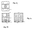
- Figs. 1a-c
- show a top view and elevations of a pallet container with a grid support structure according to a first embodiment of the present invention.
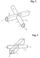
- Fig. 2
- shows an embodiment of the crossing intersection of two tubular elements.
- Fig. 3
- shows a crossing intersection in which the first tubular element is rectangular in cross-section.
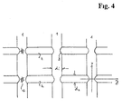
- Fig. 4
- shows an embodiment of the grid structure with the crossing in its intersections shown in Fig. 2.
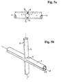
- Fig. 5a
- shows an intersection in which ridges are formed on the exterior of the second element which penetrate through the first element.
- Fig. 5b
- shows an intersection in which exterior ridges formed on the second element penetrate through the first element and engage with interior ridges of the first element.
- Fig. 6
- shows an intersection in which ridges are formed on the interior of the first element.
- Fig. 7
- shows a cross-section of the embodiment of Fig. 6 taken along the x-z plane.
- Fig. 8
- shows an intersection with three ridges formed within the first element.
- Fig. 9
- shows an intersection in which the second elements penetrates and contacts four ridges on the interior of the first element.
- Fig. 10
- shows an intersection in which the first element comprises a U-shaped profile having one inner ridge which contacts the second element.
- Fig. 11
- shows an intersection in which the second element comprises a plate having a ridge which penetrates the first element.
- Fig. 12
- shows a T-intersection of a vertical element with a rim element having two internal ridges.
- Fig. 13
- shows a T-intersection in which the rim element comprises a U-shaped profile having two inner ridges.
- Referring to Figs. 1a, 1b and 1c, a pallet container according an embodiment of the present invention comprises an inner
plastic container 10 for transporting liquids. The container is quadrangular in form and provided with anupper opening 12 and adischarge opening 14 located near the bottom wall of thecontainer 10. The bottom wall of the container is supported by thepallet 20 or a pallet-like structure located beneath thecontainer 10 for supporting the weight of the inner container. Thecontainer 10 and thepallet 20 have dimensions conforming with the relevant European Standards. Such pallets for the container may be made of wood, steel or plastic. Normally, the pallet will be constructed so as to nest with another container when stacked thereon. - The
outer support structure 30 is arranged to enclose and support the side walls of the inner container. As can be seen in Figs. 1b and 1c, the support structure encompasses the entire inner container at its side walls and is formed of a grid of first and secondelongate elements vertical elements 2 are connected torim elements 40, 50 which also circumvent the container. In the embodiment of Fig. 1b, the lower rim element 50 is interrupted at the point of thedischarge opening 14. - Embodiments of the intersections 9 are shown in Figs. 2 and 3. An
opening 3 is formed in thefirst element 1 so as to allow thesecond element 2 to penetrate therethrough. In these embodiments. The first element is a tubular member which may be circular in cross-section (Fig. 2) or rectangular (Fig. 3). The second element is also tubular and has a diameter d2 which is naturally smaller than the diameter d1 of the first tube. Preferably the outer diameter d2 of the second element is 20% to 30% smaller than the outer diameter d1 of the first element. As an example, the diameter of thefirst tube 1 can be about 22 mm with the diameter of thesecond tube 2 being 16 mm. Although both the first and second elements could be solid bars, it is preferred that both of the elements be tubular in construction. It is also possible that the first element be an open profile, which will be discussed below. - The cross-sectional profile of the tubes need not be circular and square as shown in Figs. 2 and 3, but could also be generally oval, square, triangular or even combinations of the above forms. According to the present invention, the first and
second elements second element 2 which lies opposed to the inner surface of the first element 1 (only the top position 4 is shown). For example, when theelements first tube 1 into contact with the outer wall of thesecond tube 2 under formation of the weld. In these two embodiments, thesecond tube 2 requires no further processing once purchased from the manufacturer. The first tube need only be provided with the receivinghole 3 at the proper orientation and spacing to the form the grid support structure. - The inner dimension of the receiving
opening 3 formed in thefirst element 1 is preferably sized with respect to the outer dimension d2 of thesecond element 2 such that there is no play between the receivingopening 3 and thesecond element 2. In this preferred embodiment, thesecond element 2 is then inserted through theopening 3 under the application of force to overcome friction between the outer surface of thesecond element 2 and the inner defining surfaces of the receivingopening 3. In this manner a non-positive frictional fit is established between the first andsecond elements - Fig. 4 shows an arrangement of the grid structure in which the
first elements 1 are arranged vertically and thesecond elements 2 are arranged horizontally and penetrate the firstvertical elements 1. Although this orientation is preferred, it is also possible to provide thefirst element 1 in the horizontal position with the second vertical elements penetrating therethrough in horizontal direction as shown in Figs. 1b and 1c. - In the intersection shown in Fig. 5a, the
second element 2 is provided withridges 8 which project from its outer surface. The receivingopenings 3 of thefirst element 1 is adapted to allow passage of thesecond element 2 with theridges 8. The passage may be with play or only slight friction. Once inserted to penetrate through thefirst element 1, the twoelements - As shown in Fig. 5b, the
exterior ridges 8 of thesecond element 2 penetrate theopening 3 as in Fig. 5a. In this case, the interior of thefirst element 1 is provided with twoinner ridges 5 which oppose one another about the centre axis x. In this embodiment, the crest of theexterior ridges 8 at the intersection are dimensioned to engage with the crest of theinner ridges 5 to form the connection positions. - The intersection shown in Figs. 6 and 7 include a first
tubular element 1 having tworidges 5 arranged in its interior. The dimensions of the ridges as well as the diameter of thesecond element 2 are such that two contact positions P1 and P2 arise. Thetubular element 1 of larger diameter is preprocessed to form the tworidges 5, for example by externally applying pressure to a circular tube to form a longitudinal crease or indentation 6 as shown in Fig. 6. Alternatively, the indentation could be formed only in the regions of intersection of the two elements. In addition, one or more internal ridges can be formed in the interior of the tube during the production process of the tube, whereby the outer diameter of the tube would remain circular. - As shown in Fig. 7, the second
tubular elements 2 definetangential planes second element 2 lie at the twotangential planes elements first tube 1 in the z direction. The overall width W is only slightly larger than the distance between thetangential planes smaller diameter tube 2. This is particularly advantageous for the pallet container in terms of space savings. Moreover, all surfaces at the intersection are smooth or rounded without any projecting edges. This avoids "catching" of two pallet containers during handling, for example when the containers are placed adjacent to one another. - The intersection for the grid support structure of the present invention can also be constructed as shown in Figs. 8 or 9. In Fig. 8, the first
tubular element 1 is provided with threeridges 5 formed in its interior. Thesecond element 2 penetrates the receivingopening 3 so as to contact only one of the threeinner ridges 5. In this embodiment, the twoelements smaller diameter element 2 does not intersect the centre axis x of the firsttubular element 1. As will be appreciated from the figure, the number of ridges contacted by the secondtubular element 2 will depend on its diameter and the orientation of the receiving hole for penetration. In Fig. 9, four ridges are symmetrically displaced in angular position about the interior of the firsttubular element 2. The receivingopening 3 as well as the diameter of the secondtubular element 2 is such that four contact positions a, b, c, d arise for tube connection. - Another arrangement of the intersection is shown in Fig. 10, where the first elongate element is formed as a U-shaped profile with a base 1c and two side portions 1a, 1b. Other shapes of the open profile are possible, although it is preferred that the profile have two opposing side portions 1a, 1b through which the receiving
hole 3 can be formed. In this embodiment, the side walls 1a, 1b are substantially parallel to one another and essentially flat surfaces. This allows a somewhat easier formation of the receiving holes 3a, 3b for example by means of stamping. The profile comprises at least oneridge 5 in the base 1c. Theinner ridges 5 in the side portions are shown in Fig. 10 which would include mechanical strength of theprofile 1, however which are not necessary for the connection at the intersection. Thesecond element 2 penetrates through the two holes 3a, 3b and contacts theridge 5 of the base 1c, whereby the two elements are connected to one another. - The second
elongate element 2 in the above embodiments are solid rods or tubular structures. Fig. 11 shows an embodiment in which the second element 2a is formed as a plate which passes through a correspondingly dimensioned slot 3a in the firsttubular element 1. Twoinner ridges 5 are formed within thetube 1, while an outer ridge 5a is formed on the surface of the plate 2a. When penetrated through thetube 1, the ridge 5a of the plate 2a contacts the upperinner ridge 5, whereby an intersection is formed with one connection position. In this embodiment, the slot or hole 3a is located in a relatively offset position from the central axis x of thetube 1. As can be seen in Fig. 11, the next adjacent plate member could be penetrated through a slot 3b offset from the centre axis x in the opposite direction. In this case the ridge of the plate would be directed downwardly and would contact thelower ridge 5 of thetube 1 as shown in the figure. - Returning to Figs 1a, 1b and 1c, the
grid support structure 30 comprises anupper rim 40 and a lower rim 50 to which the vertical elements of the grid are connected in a T-intersection. As mentioned above, the vertical elements can be thefirst element 1 having thehole 3 for penetration or can also be thesecond element 2. Figs. 12 and 13 show arrangements for connecting the vertical elements to theupper rim element 40. The same type of T-intersection can of course be used for the lower rim element 50. - The basic principles for forming the T-intersection are the same as those described above for the crossing intersection of the first and second elements. The
rim element 40 will be of larger dimension and correspond to the first elongate element described above. The vertical element, indicated by way of example in Fig. 1 with thereference numeral 1, will correspond to the second element described above in the crossing intersections. The main difference is that for the present T-intersections, the receivinghole 42 as shown in Fig. 12 is formed such that thevertical element 1 does not penetrate through therim element 40. In the T-intersection of Fig. 13, the opening is already provided by the open side of theU-shaped profile 40 as the rim element. Otherwise, the provisions for connecting the two elements as well as the possible forms and shapes of the respective elements are the same as in the crossing intersection described above in conjunction with the Figs. 2 to 11. - Figs. 12 and 13 show particularly suitable T-connections in which the
rim element 40 comprises two inner ridges which contact thevertical element 1 once inserted into therim element 40. - Although it is preferred that the
various elements outer tube 1 at the intersection location 4. The recess would be deep enough to form a matching recess in the outer surface of the inner second element, whereby a form fit interconnection results. - Alternatively, the
second tube 2 could be deformed either on the interior of the receivinghole 3 or outside of it. For example in the embodiments of Figs. 6 to 10, thesecond tube 2 could be provided with indentations which match the position of the inner ridges of thefirst tube 1. Engagement of the ridges in the indentations would produce a fit which would prevent axial movement of the second tube with respect to the first tube.
Claims (23)
- A pallet container comprising:an inner plastic container (10) for transporting liquids, the bottom wall of the inner container (10) supported by a pallet (20) or a pallet-like structure,a support structure (30) arranged to enclose and contact the side walls of the inner container (10) and formed as a grid of first and second elongate elements (1, 2) connected to one another at their intersections (9),wherein each first elongate element (1) has a receiving opening (3) through which the respective second elongate element (2) is passed, the first and second elongate elements (1, 2) being connected to one another at one or more positions (P1, P2) in the region of their intersection (9).
- The assembly of Claim 1, wherein an inner dimension of the receiving opening (3) of the first element (1) is dimensioned with respect to the outer dimension (d2) of the second element (2) so as to provide a frictional fit of the two elements (1, 2).
- The container of Claim 1 or 2, wherein the connection positions (P1, P2) are formed at two tangential planes (10, 20) of the grid defined by exterior surfaces of the second elements (2).
- The container of Claim 1, 2 or 3, wherein two connections are formed at the positions (P1, P2) where the outer surface of the second element (2) lies opposed to the inner surface of the first element (1)
- The container of any one of the Claims 1 to 4, wherein the first and second elements (1, 2) are tubular, the first and second elements being generally circular, oval, square triangular or rectangular in cross-section.
- The container of Claim 3, 4 or 5, wherein the outer surface of the second element (2) is provided with two ridges (8) which contact the inner surface of the first element (1) to form said two connection positions (P1, P2).
- The container of Claim 1 or 2, wherein the first elongate element (1) is tubular and comprises one or more inner ridges (5), the ridges (5) arranged to contact the outer surface of the second element (2) to form said one or more positions (P1, P2) at which the elements (1, 2) are connected.
- The container of Claim 7, wherein the first and second elements (1, 2) are tubular and circular in cross-section, the first element (1) having two inner ridges (5) formed opposite one another with respect to its centre axis (x), the two ridges (5) contacting the outer surface of the second tubular element (2) to form two positions (P1, P2) at which the elements (1, 2) are connected.
- The container of Claim 7, wherein the first element (1) comprises three inner ridges (5), the receiving opening (3) being provided such that the outer surface of the second element (2) contacts one of the inner ridges (5) at which position the elements (1, 2) are connected.
- The container of Claim 7, wherein the first element (1) comprises four inner ridges (a, b, c, d), the four ridges arranged to contact the outer surface of the second element at four positions (a, b, c, d) at which the elements (1, 2) are connected.
- The container of any one of the Claims 7 to 10, wherein the first and second elongate elements (1, 2) are tubular, the elements (1, 2) being generally circular, oval, square, triangular or rectangular in cross-section.
- The container of Claim 1 or 2, wherein the first elongate element (1) is formed as an open profile, probably a U-shaped or C-shaped profile, the profile (1) having one or more inner ridges (5) arranged to contact the outer surface of the second element to form said one or more positions (P3,) at which the elements (1, 2) are connected.
- The container of Claim 12, wherein the second elongate element (2) is tubular with its cross-section being generally circular, oval, square, triangular or rectangular.
- The container of any one of the Claims 1, 2, 7 or 12, wherein the second elongate element (2) is a plate (2a) which passes through a slot (3a) as the receiving opening in said first elongate element (1).
- The container of Claim 14, wherein the first elongate element (1) comprises a tube (1) having at least one inner ridge (5), said plate (21) having another ridge (5a) adapted to contact the inner ridge (5) of the tube (1) when inserted into the receiving opening (3) to provide for the position for connection of the two elements (1, 2).
- The container of any one of the Claims 1 to 15, wherein the first and second elongate elements (1, 2) are metal tubes and are connected at said one or more positions (P1, P2) by welding.
- The container of any one of the Claims 1 to 15, wherein the first and second elongate elements (1, 2) are made of a plastic material and the elements (1, 2) are connected at said one or more positions (P1, P2) by an adhesive or by melt-fusion bonding.
- The container of any one of the Claims 1 to 15, wherein the first and second elongate elements (1, 2) are connected at said one or more positions (P1, P2, P3) by deforming one or both of the elements (1, 2) at one or more of said positions (P1, P2, P3) so as to produce a form fit between the two elements (1, 2).
- The container of any one of the Claims 1 to 18, wherein the first elongate elements (1) of the grid support structure (30) are disposed vertically and the second elongate elements (2) are disposed horizontally or conversely, the first elongate elements (1) are disposed horizontally and the second elongate elements (2) are disposed vertically.
- The container of Claim 19, wherein the vertical elements (1, 2) at their upper and lower ends form T-intersections with upper and lower rim elements (40, 50), respectively, the rim elements (40, 50) extending about the circumference of the support structure (30).
- The container of Claim 20, wherein each T-intersection is formed by passing the vertical element (1, 2) into an opening (42) of the rim element (40, 50), while not penetrating through the rim element (40, 50).
- The container of Claim 21, wherein the vertical element (1, 2) and the rim element (40, 50) are connected to one another at one or more positions within the region of the T-intersection.
- The container of Claim 22, wherein the rim element has a closed tubular profile or an open profile, e.g. U-shaped or C-shaped, and has one or more inner ridges (80) formed therein, the inner ridges (80) arranged to contact the outer surface of the vertical element (1, 2) when passed into the rim element (40, 50).
Priority Applications (7)
| Application Number | Priority Date | Filing Date | Title |
|---|---|---|---|
| EP97119264A EP0916592B1 (en) | 1997-11-04 | 1997-11-04 | Pallet container with grid support structure |
| DE69707135T DE69707135T2 (en) | 1997-11-04 | 1997-11-04 | Pallet container with lattice support structure |
| PT97119264T PT916592E (en) | 1997-11-04 | 1997-11-04 | PALLET CONTAINER WITH GRADE SUPPORT STRUCTURE |
| AT97119264T ATE206380T1 (en) | 1997-11-04 | 1997-11-04 | PALLET CONTAINER WITH GRID SUPPORT STRUCTURE |
| DK97119264T DK0916592T3 (en) | 1997-11-04 | 1997-11-04 | Pallet container with lattice carrier structure |
| ES97119264T ES2167665T3 (en) | 1997-11-04 | 1997-11-04 | PALLET TYPE CONTAINER WITH SUPPORT STRUCTURE IN THE FORM OF A GRILLE. |
| US09/471,514 US6290082B1 (en) | 1997-11-04 | 1999-12-23 | Pallet container with grid support structure |
Applications Claiming Priority (2)
| Application Number | Priority Date | Filing Date | Title |
|---|---|---|---|
| EP97119264A EP0916592B1 (en) | 1997-11-04 | 1997-11-04 | Pallet container with grid support structure |
| US09/471,514 US6290082B1 (en) | 1997-11-04 | 1999-12-23 | Pallet container with grid support structure |
Publications (2)
| Publication Number | Publication Date |
|---|---|
| EP0916592A1 EP0916592A1 (en) | 1999-05-19 |
| EP0916592B1 true EP0916592B1 (en) | 2001-10-04 |
Family
ID=26145871
Family Applications (1)
| Application Number | Title | Priority Date | Filing Date |
|---|---|---|---|
| EP97119264A Expired - Lifetime EP0916592B1 (en) | 1997-11-04 | 1997-11-04 | Pallet container with grid support structure |
Country Status (7)
| Country | Link |
|---|---|
| US (1) | US6290082B1 (en) |
| EP (1) | EP0916592B1 (en) |
| AT (1) | ATE206380T1 (en) |
| DE (1) | DE69707135T2 (en) |
| DK (1) | DK0916592T3 (en) |
| ES (1) | ES2167665T3 (en) |
| PT (1) | PT916592E (en) |
Families Citing this family (15)
| Publication number | Priority date | Publication date | Assignee | Title |
|---|---|---|---|---|
| ES2167665T3 (en) | 1997-11-04 | 2002-05-16 | Royal Packaging Industry Van L | PALLET TYPE CONTAINER WITH SUPPORT STRUCTURE IN THE FORM OF A GRILLE. |
| US6758360B2 (en) | 1999-12-23 | 2004-07-06 | Royal Packaging Industry Leer N.V. | Pallet container with grid support structure |
| DE10103656A1 (en) * | 2000-05-25 | 2001-12-06 | Mauser Werke Gmbh & Co Kg | Palletized container for dangerous liquids has thin-walled plastic container on a pallet and surrounded by a welded cage |
| US6722291B2 (en) | 2002-03-19 | 2004-04-20 | Slooters, Inc. | Separation members for selective placement between sheet members oriented horizontally and stacked vertically and method of usage thereof |
| NL1020438C2 (en) * | 2002-04-19 | 2003-10-21 | Leer Koninklijke Emballage | IBC for flammable products. |
| DE20216058U1 (en) * | 2002-10-18 | 2003-02-06 | Richter Guenter | Container with an inner container and a latticed outer shell body |
| DE10301517B3 (en) * | 2003-01-17 | 2004-03-11 | Protechna S.A. | Transport and storage container for liquid has vertical grid rods of grid mantle enclosing inner plastics container welded to upper edge profile supporting stacked container |
| US20040177589A1 (en) * | 2003-03-14 | 2004-09-16 | United Integrated Services Co., Ltd. | Raised floor panel fabrication method |
| DE502004000779D1 (en) * | 2003-04-25 | 2006-07-27 | Mauser Werke Gmbh & Co Kg | PALETTE CONTAINER |
| US7399942B2 (en) * | 2006-01-06 | 2008-07-15 | Gm Global Technology Operations, Inc. | Method for projection bonding of telescoped tubes |
| DE202012001726U1 (en) * | 2012-02-20 | 2012-06-14 | Dietmar Przytulla | pallet container |
| WO2014044374A1 (en) * | 2012-09-21 | 2014-03-27 | Mauser-Werke Gmbh | Pallet container |
| FR3037319A1 (en) * | 2015-06-12 | 2016-12-16 | Sotralentz Packaging | STACKABLE PALLET CONTAINER WITH SUPERIOR REINFORCEMENT FRAME |
| DE102017006653B4 (en) * | 2017-07-13 | 2023-10-26 | Mauser-Werke Gmbh | Pallet container |
| IT201700095075A1 (en) * | 2017-08-22 | 2019-02-22 | Maschio N S S R L | METALLIC CAGE FOR TANKS. |
Family Cites Families (12)
| Publication number | Priority date | Publication date | Assignee | Title |
|---|---|---|---|---|
| GB1051857A (en) * | ||||
| SE319454B (en) * | 1967-08-23 | 1970-01-19 | S Dubois | |
| GB2106948A (en) | 1981-09-22 | 1983-04-20 | Brian Harmer | Metal floor-grating |
| GB2133430A (en) | 1982-12-24 | 1984-07-25 | John Raymond Williams | Metallic structure |
| DE3344351A1 (en) | 1983-12-08 | 1985-06-27 | Allendorfer Fabrik für Stahlverarbeitung Ing. Herbert Panne GmbH & Co KG, 6349 Greifenstein | Grate |
| US4676373A (en) * | 1984-11-20 | 1987-06-30 | Helmhold Schneider | Plastic pallet container |
| DE3819911A1 (en) * | 1988-06-11 | 1989-12-14 | Schuetz Werke Gmbh Co Kg | PALLET CONTAINER |
| US4909387A (en) * | 1988-11-24 | 1990-03-20 | Schuetz Udo | Pallet container with an exchangeable inner container of a synthetic resin and an outer jacket of metal lattice bars |
| DK168243B1 (en) | 1989-08-14 | 1994-02-28 | Fiberline As | profile Collection |
| DE19511723C1 (en) * | 1995-03-30 | 1996-08-29 | Protechna Sa | Pallet container |
| GB9515460D0 (en) | 1995-07-27 | 1995-09-27 | Mita Uk Ltd | Structural support system and method for its manufacture pultruded grp grating |
| ES2167665T3 (en) | 1997-11-04 | 2002-05-16 | Royal Packaging Industry Van L | PALLET TYPE CONTAINER WITH SUPPORT STRUCTURE IN THE FORM OF A GRILLE. |
-
1997
- 1997-11-04 ES ES97119264T patent/ES2167665T3/en not_active Expired - Lifetime
- 1997-11-04 PT PT97119264T patent/PT916592E/en unknown
- 1997-11-04 DK DK97119264T patent/DK0916592T3/en active
- 1997-11-04 AT AT97119264T patent/ATE206380T1/en active
- 1997-11-04 EP EP97119264A patent/EP0916592B1/en not_active Expired - Lifetime
- 1997-11-04 DE DE69707135T patent/DE69707135T2/en not_active Expired - Lifetime
-
1999
- 1999-12-23 US US09/471,514 patent/US6290082B1/en not_active Expired - Lifetime
Also Published As
| Publication number | Publication date |
|---|---|
| PT916592E (en) | 2002-03-28 |
| DE69707135T2 (en) | 2002-06-20 |
| EP0916592A1 (en) | 1999-05-19 |
| ES2167665T3 (en) | 2002-05-16 |
| DE69707135D1 (en) | 2001-11-08 |
| ATE206380T1 (en) | 2001-10-15 |
| DK0916592T3 (en) | 2002-01-28 |
| US6290082B1 (en) | 2001-09-18 |
Similar Documents
| Publication | Publication Date | Title |
|---|---|---|
| US6758360B2 (en) | Pallet container with grid support structure | |
| EP0916592B1 (en) | Pallet container with grid support structure | |
| RU2104238C1 (en) | Container with pan for transportation and storage of liquids | |
| CA2174920C (en) | Modular spill deck | |
| KR101526302B1 (en) | Pallet container | |
| US11352169B2 (en) | Pallet assembly | |
| US6688803B2 (en) | Connection assembly | |
| US5738240A (en) | Composite shipping container with tubular member pallet | |
| JP2001341741A (en) | Pallet container | |
| JP2779232B2 (en) | Containers for transporting and / or storing liquids and finely dispersed bulk materials | |
| EP2617660A1 (en) | Pallet container for liquids | |
| CA2409852C (en) | Pallet container | |
| US3538861A (en) | Materials handling pallet | |
| EP0916777B1 (en) | A connection assembly | |
| KR20030070018A (en) | Pallet container | |
| KR101994281B1 (en) | Pallet container | |
| JP7174075B2 (en) | Liquid transport and storage containers | |
| JPH0516106Y2 (en) | ||
| JP7382051B2 (en) | palette | |
| EP1457617B1 (en) | A grid structure | |
| JP2021109658A (en) | Pallet | |
| RU2205778C2 (en) | Sectional tray | |
| IL153019A (en) | Pallet container | |
| KR200322754Y1 (en) | Paper pallet | |
| JPS5931593Y2 (en) | Reinforcement unit plate for tank assembly |
Legal Events
| Date | Code | Title | Description |
|---|---|---|---|
| PUAI | Public reference made under article 153(3) epc to a published international application that has entered the european phase |
Free format text: ORIGINAL CODE: 0009012 |
|
| AK | Designated contracting states |
Kind code of ref document: A1 Designated state(s): AT BE CH DE DK ES FI FR GB GR IE IT LI LU MC NL PT SE |
|
| AX | Request for extension of the european patent |
Free format text: AL;LT;LV;MK;RO;SI |
|
| 17P | Request for examination filed |
Effective date: 19991119 |
|
| AKX | Designation fees paid |
Free format text: AT BE CH DE DK ES FI FR GB GR IE IT LI LU MC NL PT SE |
|
| RAP1 | Party data changed (applicant data changed or rights of an application transferred) |
Owner name: ROYAL PACKAGING INDUSTRY VAN LEER N.V. |
|
| GRAG | Despatch of communication of intention to grant |
Free format text: ORIGINAL CODE: EPIDOS AGRA |
|
| 17Q | First examination report despatched |
Effective date: 20001006 |
|
| GRAG | Despatch of communication of intention to grant |
Free format text: ORIGINAL CODE: EPIDOS AGRA |
|
| GRAH | Despatch of communication of intention to grant a patent |
Free format text: ORIGINAL CODE: EPIDOS IGRA |
|
| GRAH | Despatch of communication of intention to grant a patent |
Free format text: ORIGINAL CODE: EPIDOS IGRA |
|
| GRAA | (expected) grant |
Free format text: ORIGINAL CODE: 0009210 |
|
| AK | Designated contracting states |
Kind code of ref document: B1 Designated state(s): AT BE CH DE DK ES FI FR GB GR IE IT LI LU MC NL PT SE |
|
| PG25 | Lapsed in a contracting state [announced via postgrant information from national office to epo] |
Ref country code: LI Free format text: LAPSE BECAUSE OF FAILURE TO SUBMIT A TRANSLATION OF THE DESCRIPTION OR TO PAY THE FEE WITHIN THE PRESCRIBED TIME-LIMIT Effective date: 20011004 Ref country code: CH Free format text: LAPSE BECAUSE OF FAILURE TO SUBMIT A TRANSLATION OF THE DESCRIPTION OR TO PAY THE FEE WITHIN THE PRESCRIBED TIME-LIMIT Effective date: 20011004 |
|
| REF | Corresponds to: |
Ref document number: 206380 Country of ref document: AT Date of ref document: 20011015 Kind code of ref document: T |
|
| REG | Reference to a national code |
Ref country code: CH Ref legal event code: EP |
|
| PG25 | Lapsed in a contracting state [announced via postgrant information from national office to epo] |
Ref country code: MC Free format text: LAPSE BECAUSE OF NON-PAYMENT OF DUE FEES Effective date: 20011104 Ref country code: LU Free format text: LAPSE BECAUSE OF NON-PAYMENT OF DUE FEES Effective date: 20011104 |
|
| PG25 | Lapsed in a contracting state [announced via postgrant information from national office to epo] |
Ref country code: IE Free format text: LAPSE BECAUSE OF FAILURE TO SUBMIT A TRANSLATION OF THE DESCRIPTION OR TO PAY THE FEE WITHIN THE PRESCRIBED TIME-LIMIT Effective date: 20011105 |
|
| REF | Corresponds to: |
Ref document number: 69707135 Country of ref document: DE Date of ref document: 20011108 |
|
| REG | Reference to a national code |
Ref country code: IE Ref legal event code: FG4D |
|
| REG | Reference to a national code |
Ref country code: GB Ref legal event code: IF02 |
|
| REG | Reference to a national code |
Ref country code: DK Ref legal event code: T3 |
|
| ET | Fr: translation filed | ||
| REG | Reference to a national code |
Ref country code: PT Ref legal event code: SC4A Free format text: AVAILABILITY OF NATIONAL TRANSLATION Effective date: 20020103 |
|
| REG | Reference to a national code |
Ref country code: CH Ref legal event code: PL |
|
| REG | Reference to a national code |
Ref country code: ES Ref legal event code: FG2A Ref document number: 2167665 Country of ref document: ES Kind code of ref document: T3 |
|
| REG | Reference to a national code |
Ref country code: GR Ref legal event code: EP Ref document number: 20020400011 Country of ref document: GR |
|
| PLBE | No opposition filed within time limit |
Free format text: ORIGINAL CODE: 0009261 |
|
| STAA | Information on the status of an ep patent application or granted ep patent |
Free format text: STATUS: NO OPPOSITION FILED WITHIN TIME LIMIT |
|
| REG | Reference to a national code |
Ref country code: IE Ref legal event code: MM4A |
|
| 26N | No opposition filed | ||
| PGFP | Annual fee paid to national office [announced via postgrant information from national office to epo] |
Ref country code: DK Payment date: 20081119 Year of fee payment: 12 |
|
| PGFP | Annual fee paid to national office [announced via postgrant information from national office to epo] |
Ref country code: PT Payment date: 20081024 Year of fee payment: 12 Ref country code: FI Payment date: 20081126 Year of fee payment: 12 |
|
| PGFP | Annual fee paid to national office [announced via postgrant information from national office to epo] |
Ref country code: SE Payment date: 20081105 Year of fee payment: 12 |
|
| PGFP | Annual fee paid to national office [announced via postgrant information from national office to epo] |
Ref country code: GR Payment date: 20081127 Year of fee payment: 12 |
|
| REG | Reference to a national code |
Ref country code: PT Ref legal event code: MM4A Free format text: LAPSE DUE TO NON-PAYMENT OF FEES Effective date: 20100504 |
|
| EUG | Se: european patent has lapsed | ||
| REG | Reference to a national code |
Ref country code: DK Ref legal event code: EBP |
|
| PG25 | Lapsed in a contracting state [announced via postgrant information from national office to epo] |
Ref country code: PT Free format text: LAPSE BECAUSE OF NON-PAYMENT OF DUE FEES Effective date: 20100504 |
|
| PG25 | Lapsed in a contracting state [announced via postgrant information from national office to epo] |
Ref country code: FI Free format text: LAPSE BECAUSE OF NON-PAYMENT OF DUE FEES Effective date: 20091104 |
|
| PG25 | Lapsed in a contracting state [announced via postgrant information from national office to epo] |
Ref country code: GR Free format text: LAPSE BECAUSE OF NON-PAYMENT OF DUE FEES Effective date: 20100602 |
|
| PG25 | Lapsed in a contracting state [announced via postgrant information from national office to epo] |
Ref country code: DK Free format text: LAPSE BECAUSE OF NON-PAYMENT OF DUE FEES Effective date: 20091130 |
|
| PG25 | Lapsed in a contracting state [announced via postgrant information from national office to epo] |
Ref country code: SE Free format text: LAPSE BECAUSE OF NON-PAYMENT OF DUE FEES Effective date: 20091105 |
|
| PGFP | Annual fee paid to national office [announced via postgrant information from national office to epo] |
Ref country code: AT Payment date: 20131127 Year of fee payment: 17 Ref country code: GB Payment date: 20131202 Year of fee payment: 17 |
|
| PGFP | Annual fee paid to national office [announced via postgrant information from national office to epo] |
Ref country code: NL Payment date: 20131127 Year of fee payment: 17 Ref country code: FR Payment date: 20131129 Year of fee payment: 17 Ref country code: IT Payment date: 20131126 Year of fee payment: 17 Ref country code: ES Payment date: 20131220 Year of fee payment: 17 |
|
| PGFP | Annual fee paid to national office [announced via postgrant information from national office to epo] |
Ref country code: BE Payment date: 20131223 Year of fee payment: 17 |
|
| PGFP | Annual fee paid to national office [announced via postgrant information from national office to epo] |
Ref country code: DE Payment date: 20140130 Year of fee payment: 17 |
|
| REG | Reference to a national code |
Ref country code: DE Ref legal event code: R119 Ref document number: 69707135 Country of ref document: DE |
|
| REG | Reference to a national code |
Ref country code: NL Ref legal event code: V1 Effective date: 20150601 |
|
| PG25 | Lapsed in a contracting state [announced via postgrant information from national office to epo] |
Ref country code: BE Free format text: LAPSE BECAUSE OF NON-PAYMENT OF DUE FEES Effective date: 20141130 |
|
| REG | Reference to a national code |
Ref country code: AT Ref legal event code: MM01 Ref document number: 206380 Country of ref document: AT Kind code of ref document: T Effective date: 20141104 |
|
| GBPC | Gb: european patent ceased through non-payment of renewal fee |
Effective date: 20141104 |
|
| REG | Reference to a national code |
Ref country code: FR Ref legal event code: ST Effective date: 20150731 |
|
| PG25 | Lapsed in a contracting state [announced via postgrant information from national office to epo] |
Ref country code: NL Free format text: LAPSE BECAUSE OF NON-PAYMENT OF DUE FEES Effective date: 20150601 Ref country code: AT Free format text: LAPSE BECAUSE OF NON-PAYMENT OF DUE FEES Effective date: 20141104 |
|
| PG25 | Lapsed in a contracting state [announced via postgrant information from national office to epo] |
Ref country code: GB Free format text: LAPSE BECAUSE OF NON-PAYMENT OF DUE FEES Effective date: 20141104 Ref country code: DE Free format text: LAPSE BECAUSE OF NON-PAYMENT OF DUE FEES Effective date: 20150602 |
|
| PG25 | Lapsed in a contracting state [announced via postgrant information from national office to epo] |
Ref country code: FR Free format text: LAPSE BECAUSE OF NON-PAYMENT OF DUE FEES Effective date: 20141201 |
|
| REG | Reference to a national code |
Ref country code: ES Ref legal event code: FD2A Effective date: 20151229 |
|
| PG25 | Lapsed in a contracting state [announced via postgrant information from national office to epo] |
Ref country code: IT Free format text: LAPSE BECAUSE OF NON-PAYMENT OF DUE FEES Effective date: 20141104 |
|
| PG25 | Lapsed in a contracting state [announced via postgrant information from national office to epo] |
Ref country code: ES Free format text: LAPSE BECAUSE OF NON-PAYMENT OF DUE FEES Effective date: 20141105 |