EP0915784B1 - Verfahren zum herstellen einer versteifungsleiste für eine extrudierte wischlippe eines scheibenwischers - Google Patents
Verfahren zum herstellen einer versteifungsleiste für eine extrudierte wischlippe eines scheibenwischers Download PDFInfo
- Publication number
- EP0915784B1 EP0915784B1 EP97934397A EP97934397A EP0915784B1 EP 0915784 B1 EP0915784 B1 EP 0915784B1 EP 97934397 A EP97934397 A EP 97934397A EP 97934397 A EP97934397 A EP 97934397A EP 0915784 B1 EP0915784 B1 EP 0915784B1
- Authority
- EP
- European Patent Office
- Prior art keywords
- metal strip
- flat metal
- claw
- squeegee
- barb
- Prior art date
- Legal status (The legal status is an assumption and is not a legal conclusion. Google has not performed a legal analysis and makes no representation as to the accuracy of the status listed.)
- Expired - Lifetime
Links
- 238000004519 manufacturing process Methods 0.000 title claims description 6
- 210000000078 claw Anatomy 0.000 claims abstract description 54
- 239000002184 metal Substances 0.000 claims abstract description 53
- 230000014759 maintenance of location Effects 0.000 claims abstract description 7
- 238000000034 method Methods 0.000 claims description 20
- 238000005520 cutting process Methods 0.000 claims description 7
- 230000000717 retained effect Effects 0.000 claims description 4
- 238000004080 punching Methods 0.000 claims description 3
- 230000015572 biosynthetic process Effects 0.000 claims 1
- 239000011324 bead Substances 0.000 description 3
- 239000000463 material Substances 0.000 description 3
- 230000035515 penetration Effects 0.000 description 2
- 238000005096 rolling process Methods 0.000 description 2
- 230000000712 assembly Effects 0.000 description 1
- 238000000429 assembly Methods 0.000 description 1
- 230000008878 coupling Effects 0.000 description 1
- 238000010168 coupling process Methods 0.000 description 1
- 238000005859 coupling reaction Methods 0.000 description 1
- 230000001419 dependent effect Effects 0.000 description 1
- 238000011161 development Methods 0.000 description 1
- 230000018109 developmental process Effects 0.000 description 1
- 238000001125 extrusion Methods 0.000 description 1
- 238000000465 moulding Methods 0.000 description 1
- 230000000149 penetrating effect Effects 0.000 description 1
- 238000000926 separation method Methods 0.000 description 1
- 238000007493 shaping process Methods 0.000 description 1
- 229910001220 stainless steel Inorganic materials 0.000 description 1
- 239000002699 waste material Substances 0.000 description 1
Images


Classifications
-
- B—PERFORMING OPERATIONS; TRANSPORTING
- B60—VEHICLES IN GENERAL
- B60S—SERVICING, CLEANING, REPAIRING, SUPPORTING, LIFTING, OR MANOEUVRING OF VEHICLES, NOT OTHERWISE PROVIDED FOR
- B60S1/00—Cleaning of vehicles
- B60S1/02—Cleaning windscreens, windows or optical devices
- B60S1/04—Wipers or the like, e.g. scrapers
- B60S1/32—Wipers or the like, e.g. scrapers characterised by constructional features of wiper blade arms or blades
- B60S1/38—Wiper blades
- B60S1/3801—Wiper blades characterised by a blade support harness consisting of several articulated elements
-
- B—PERFORMING OPERATIONS; TRANSPORTING
- B60—VEHICLES IN GENERAL
- B60S—SERVICING, CLEANING, REPAIRING, SUPPORTING, LIFTING, OR MANOEUVRING OF VEHICLES, NOT OTHERWISE PROVIDED FOR
- B60S1/00—Cleaning of vehicles
- B60S1/02—Cleaning windscreens, windows or optical devices
- B60S1/04—Wipers or the like, e.g. scrapers
- B60S1/32—Wipers or the like, e.g. scrapers characterised by constructional features of wiper blade arms or blades
- B60S1/38—Wiper blades
- B60S2001/3812—Means of supporting or holding the squeegee or blade rubber
- B60S2001/3817—Means of supporting or holding the squeegee or blade rubber chacterised by a backing strip to aid mounting of squeegee in support
- B60S2001/382—Means of supporting or holding the squeegee or blade rubber chacterised by a backing strip to aid mounting of squeegee in support the backing strip being an essentially planar reinforcing strip, e.g. vertebra
-
- Y—GENERAL TAGGING OF NEW TECHNOLOGICAL DEVELOPMENTS; GENERAL TAGGING OF CROSS-SECTIONAL TECHNOLOGIES SPANNING OVER SEVERAL SECTIONS OF THE IPC; TECHNICAL SUBJECTS COVERED BY FORMER USPC CROSS-REFERENCE ART COLLECTIONS [XRACs] AND DIGESTS
- Y10—TECHNICAL SUBJECTS COVERED BY FORMER USPC
- Y10T—TECHNICAL SUBJECTS COVERED BY FORMER US CLASSIFICATION
- Y10T29/00—Metal working
- Y10T29/49—Method of mechanical manufacture
- Y10T29/49616—Structural member making
- Y10T29/49622—Vehicular structural member making
-
- Y—GENERAL TAGGING OF NEW TECHNOLOGICAL DEVELOPMENTS; GENERAL TAGGING OF CROSS-SECTIONAL TECHNOLOGIES SPANNING OVER SEVERAL SECTIONS OF THE IPC; TECHNICAL SUBJECTS COVERED BY FORMER USPC CROSS-REFERENCE ART COLLECTIONS [XRACs] AND DIGESTS
- Y10—TECHNICAL SUBJECTS COVERED BY FORMER USPC
- Y10T—TECHNICAL SUBJECTS COVERED BY FORMER US CLASSIFICATION
- Y10T29/00—Metal working
- Y10T29/49—Method of mechanical manufacture
- Y10T29/49995—Shaping one-piece blank by removing material
- Y10T29/49996—Successive distinct removal operations
Definitions
- This invention relates to a backing strip, also known as a vertebra or spine, and used in association with a rubber squeegee in windshield wiper assemblies to stiffen the squeegee and to provide mounting attachments for coupling the squeegee to the windshield wiper superstructure.
- One form of backing strip comprises a flat metal strip having a central longitudinal slot dividing the strip into a pair of rails and into which the neck portion of a molded rubber squeegee is positioned with the retention bead of the squeegee lying between the backing strip and the wiper superstructure.
- the rails may be joined at the ends of the strip if the slot is made to extend slightly less than the full length of the backing strip or the rails may be separate and coupled at the ends of the backing strip by means of a clip.
- the squeegee itself has usually been fabricated with location means during a molding process whereas, in the latter, the squeegee may be fabricated by extrusion which greatly improves tolerances and consistency in the squeegee profile, thereby improving productivity and reducing costs.
- Some backing strip structures comprising rail pairs have been proposed in which at least one rail is formed with a barb portion for penetrating the squeegee and to thereby prevent relative longitudinal movement between the backing strip and the squeegee and obviate the need to use a clip. Examples of such structures may be found in GB-A-2,243,991 and DE-A-3,208,749.
- the barb is longitudinally spaced from an abutment or notch-like structure which cooperates with a claw in the end yoke of a wiper superstructure to attach to the spine.
- GB-A-2 292 672 refers to a rail whose portion provided with a claw retaining notch is shifted and offset transversely to the longitudinal axis of the rail. However, said offset portion remains spaced from barb elements along the length of the rail. Shifting the portion of the claw retaining notch of DE-A-3 208 749 - as taught by GB-A-2 292 672 - would not lead the skilled person to achieve a rail in which the same shifted offset portion would include both a claw retaining notch and the barb elements, such that the spacing between a barb and a notch is minimized and the squeegee is directly applied to the barb elements.
- An object of this invention is to provide a method of fabricating such a spine structure which is economical and easy and to provide a structure for a backing strip which will reliably couple the squeegee to the windshield wiper superstructure by minimizing the longitudinal separation between squeegee retaining barbs and a claw retaining notch.
- the invention also provides for a rail made by a method in accordance with the invention, see also claims 5 and 10.
- a backing strip made in accordance with the invention is generally designated by numeral 20 in Fig. 2 of the drawings.
- the backing strip 20 which is also known as a vertebra or spine is associated with a rubber squeegee 22 in a windshield wiper assembly and is used to stiffen the squeegee throughout its length while allowing the squeegee to flex in an orthogonal direction to the length of the squeegee so that it can conform to the surface of a curved windshield.
- the backing strip 20 is attached to a windshield wiper superstructure by means of a claw termination 24 on a yoke 26 forming part of a wiper superstructure.
- the backing strip 20 comprises a pair of congruent rails 28, 30 of which one is shown in greater detail in Fig. 1.
- Each rail is fabricated from a blank comprising a flat metal strip of narrow width and would typically be formed by rolling stainless steel wire having a selected diameter.
- the strip formed by rolling the wire will typically have a width of 25 mm and a thickness of 8 mm.
- the strip itself may be of indefinite length or cut to predetermined lengths commensurate with the size of the windshield wiper superstructure with which the backing strip is intended to be used.
- An intermediate portion 32 of the backing strip 20 adjacent one end of the strip is shaped to receive the claw termination 24 and has retention means for securing the rails 28, 30 to the squeegee 22.
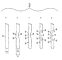
- Fig. 3a shows a blank 34 comprising the above-mentioned flat metal strip.
- the blank 34 is formed with an offset portion 36 shifted transversely from a longitudinal axis defined by the length of the strip so as to protrude from the remainder of the strip on one side, a hollow 38 being defined on the opposite side of the strip during such deformation.
- the position of the offset portion 36 is selected to be adjacent one end of the strip and spaced from the end by a distance commensurate with the claw position in the intended superstructure. This step is shown in Fig. 3b.
- the offset portion 36 is edge-punched to form a claw retaining notch 40 defined by a pair of longitudinally-spaced abutments 42 and adapted to locate a claw, such as the claw termination 24, therebetween. This step is shown in Fig. 3c.
- a longitudinally extending opening 44 is cut from the intermediate portion 32 at the hollow 38 and the opening 44 is shaped so that the metal adjacent to the hollow forms a pair of barb elements 46 of reduced cross-sectional width.
- the opening 44 is opposite the claw retaining notch 40 and is transversely aligned therewith. This step is shown in Fig. 3d. It will be seen that the notch 40 is disposed on the opposite side of the rail between the barb elements 46 and that the barb elements 46 have pointed terminations which will penetrate the rubber material of the squeegee 22.
- the barb elements 46 are pulled outwardly in a direction transverse to the aforementioned longitudinal axis so as to protrude outwardly from the rail. If the blank 20 is of indefinite length, it would also be trimmed to the required length to match the intended wiper superstructure.
- the processing sequence allows a claw retaining notch 40 to be cut after deformation of the blank 34 and therefore there is very little wasted material which must be discarded or recycled.
- the deformation also selectively increases the effective width of the rail indicated by "w" in Fig. 3b so that it exceeds the nominal width of the blank indicated by "n” in Fig. 3a.
- the increased width in the intermediate portion 32 accommodates both the claw retaining notch 40 and the opening 44 to form the barb elements 46 so that they can be formed on opposite sides of the rail.
- the method in accordance with the invention, permits the barb elements to be disposed in the immediate vicinity of the notch for receiving the claw termination without waste of material and without unduly increasing the width of the strip to exceed accepted standards in the industry which could otherwise necessitate changes in the fabrication of both the squeegee and the wiper superstructure.
- the rails 28, 30 are each disposed on opposite sides of the squeegee 22 in respective longitudinal grooves which define a reduced diameter neck portion 48 in the squeegee with a retention bead 50 of the squeegee lying between the rails 28, 30 and the wiper superstructure.
- the rails 28, 30 are oriented so that the respective claw retaining notches 40 open outwardly to receive and locate respective ends of claw terminations of the wiper superstructure 24 while the barb elements 46 are oriented so as to penetrate the reduced diameter neck portion 48 of the squeegee 22.
- deformation of the blank 34 to form the offset portion 36 may reduce the thickness of the flat metal strip so that the barb elements 46 formed proximate to the claw retaining notch 40 are possibly too thin for effective penetration into the rubber squeegee.
- the associated openings may be cut from the intermediate portion 32 of the blank 34 in the area immediately adjacent the offset portion 36.
- a pair of openings 52, 54 are cut from the intermediate portion 32.
- the openings 52, 54 are longitudinally spaced from each other on the flat metal strip with the hollow 38 disposed between the openings 52, 54.
- Each opening 52, 54 forms a respective pair of oppositely directed barb elements 56, 58 having a reduced cross-sectional width of which the inner barb elements 56, 58 are formed from metal adjacent to the hollow 38.
- the barb elements 56, 58 are subsequently pulled outwardly to protrude from the flat metal strip and are adapted to penetrate a rubber squeegee.
- the barb elements 56, 58 form a 30° angle with respect to the longitudinal axis of the flat metal strip. If a more pronounced angle is required for greater penetration into the squeegee, the barb elements 56, 58 may be further bent to form an angle of 55° with respect to the longitudinal axis of the flat metal strip, as shown in Fig. 4f.
- a pair of openings 60, 62 are cut from the intermediate portion 32 and the openings 60, 62 are longitudinally spaced from each other on the flat metal strip with the hollow 38 disposed between the openings 60, 62.
- the openings 60, 62 are shaped to form only a single respective barb element 64, 66 formed from the metal adjacent to the hollow 38 and oppositely directed from one another.
- the barb elements 64, 66 are subsequently pulled outwardly to protrude from the flat metal strip and form an angle of 30° with respect to the longitudinal axis of the flat metal strip as shown in Fig. 5e and can be further pulled to form an angle of up to 60° as shown in Fig. 5f.
Landscapes
- Engineering & Computer Science (AREA)
- Mechanical Engineering (AREA)
- Seal Device For Vehicle (AREA)
- Extrusion Moulding Of Plastics Or The Like (AREA)
- Brushes (AREA)
- Punching Or Piercing (AREA)
- Laminated Bodies (AREA)
Claims (14)
- Verfahren zum Herstellen einer Schiene (28, 30), die einen Teil einer Versteifungsleiste (20) für einen Wischgummi (22) eines Scheibenwischers bildet, ausgehend von einer Vorform (34), die aus einem flachen Metallstreifen besteht, welcher eine schmale Breite aufweist und eine Längsachse festlegt, wobei das Verfahren die folgenden Schritte umfasst :Stanzen der Kante an einem Teilstück des flachen Metallstreifens zur Bildung einer eine Klaue zurückhaltenden Kerbe (40), die angepasst ist um eine Klaue (24) aufzunehmen, welche einen Teil der Oberstruktur (26) eines Scheibenwischers bildet,Schneiden von wenigstens einer Öffnung (44) in das besagte Teilstück, so dass das Metall wenigstens ein den Wischgummi zurückhaltendes Widerhakenelement (46) mit einer verkleinerten Querschnittsbreite bildet; undZiehen des wenigstens einen Widerhakenelementes (46) nach außen in einer Richtung schräg zu der besagten Längsachse, so dass es ausgehend von dem flachen Metallstreifen nach außen vorsteht, dadurch gekennzeichnet, dassa) das Verfahren einen ersten Schritt umfasst zur Bildung eines verlängerten versetzten Teilstückes (36) von einer vorgegebenen Länge an einem Zwischenabschnitt (32) des flachen Metallstreifens, wobei das versetzte Teilstück (36) derart transversal zu der besagten Längsachse verschoben wird, dass es aus dem verbleibenden Teil des flachen Metallstreifens auf einer einzigen Seite desselben übersteht, wobei das versetzte Teilstück (36) einen Hohlraum (38) begrenzt, welcher auf einer gegenüberliegenden Seite des flachen Metallstreifens angeordnet ist;b) das besagte versetzte Teilstück (36) an einer Kante gestanzt wird, um die besagte eine Klaue zurückhaltende Kerbe (40) zu bilden;c) die besagte wenigstens eine Öffnung (44) derart in den Zwischenabschnitt (32) geschnitten wird, dass das an den besagten Hohlraum (38) angrenzende Metall wenigstens ein einen Wischgummi zurückhaltendes Widerhakenelement (46) mit einer verkleinerten Querschnittsbreite bildet, wobei das wenigstens eine Widerhakenelement (46) in der Nähe der eine Klaue zurückhaltenden Kerbe (40) liegt, so dass ein Druck, der über die Oberstruktur (26) auf den Scheibenwischer ausgeübt wird und der durch eine Klaue (24), die in der die Klaue zurückhaltenden Kerbe (40) festgehalten wird, weitergeleitet wird zu der Schiene (28, 30), das wenigstens eine Widerhakenelement (46) in den Eingriff mit dem Wischgummi (22) drängt.
- Verfahren gemäß Anspruch 1, bei welchem die Vorform (34) vor der Bildung des versetzten Teilstücks (36) vorweg auf eine gewünschte Länge geschnitten wird und das versetzte Teilstück (36) angrenzend an ein Ende der Vorform (34) gebildet wird, in einer vorherbestimmten Entfernung von dem Ende der Vorform (34) im Einklang mit der relativen Stellung der Klaue (24) in einer ausgewählten Oberstruktur (26) eines Scheibenwischers.
- Verfahren gemäß Anspruch 1, bei welchem das versetzte Teilstück (36) an der Kante gestanzt wird, um ein Paar Widerlager (42) zu bilden, welche die eine Klaue zurückhaltende Kerbe (40) definieren.
- Verfahren gemäß Anspruch 1, bei welchem ein Paar von in entgegengesetzten Richtungen orientierten Widerhakenelementen (46) aus dem Zwischenabschnitt (32) ausgeschnitten werden.
- Verfahren zum Herstellen einer Schiene (28, 30), die einen Teil einer Versteifungsleiste (20) für einen Wischgummi (22) eines Scheibenwischers bildet, ausgehend von einer Vorform (34), die aus einem flachen Metallstreifen besteht, welcher eine schmale Breite aufweist und eine Längsachse festlegt, wobei das Verfahren die folgenden Schritte umfasst :Stanzen der Kante an einem Teilstück des flachen Metallstreifens zur Bildung einer eine Klaue zurückhaltenden Kerbe (40), die angepasst ist um eine Klaue (24) aufzunehmen, welche einen Teil der Oberstruktur (26) eines Scheibenwischers bildet;Schneiden von wenigstens einer Öffnung (44) in das besagte Teilstück, so dass das Metall wenigstens ein den Wischgummi zurückhaltendes Widerhakenelement (46) mit einer verkleinerten Querschnittsbreite bildet; undZiehen des wenigstens einen Widerhakenelementes (46) nach außen in einer Richtung schräg zu der besagten Längsachse, so dass es ausgehend von dem flachen Metallstreifen nach außen vorsteht, dadurch gekennzeichnet, dassa) das Verfahren einen ersten Schritt umfasst zur Bildung eines verlängerten versetzten Teilstückes (36) von einer vorgegebenen Länge an einem Zwischenabschnitt (32) des flachen Metallstreifens, wobei das versetzte Teilstück (36) derart transversal zu der besagten Längsachse verschoben wird, dass es aus dem verbleibenden Teil des flachen Metallstreifens auf einer einzigen Seite desselben übersteht, wobei das versetzte Teilstück (36) einen Hohlraum (38) begrenzt, welcher auf einer gegenüberliegenden Seite des flachen Metallstreifens angeordnet ist;b) das besagte versetzte Teilstück (36) an einer Kante gestanzt wird, um die besagte eine Klaue zurückhaltende Kerbe (40) zu bilden;c) die besagte wenigstens eine Öffnung (44) in den Zwischenabschnitt (32) geschnitten wird, um wenigstens ein Paar von einen Wischgummi zurückhaltenden Widerhakenelementen (46) mit einer verkleinerten Querschnittsbreite zu bilden, dies auf der gegenüberliegenden Seite in Bezug auf das versetzte Teilstück (36) aus dem flachen Metallstreifen und in der Nähe der eine Klaue zurückhaltenden Kerbe (40), wobei die Widerhakenelemente (46) das eine in der Längsrichtung von dem anderen entfernt an dem Metallstreifen angeordnet sind während die die Klaue zurückhaltende Kerbe (40) zwischen wenigstens zwei Widerhakenelementen (46) eingerichtet ist, wodurch die besagten Widerhakenelemente derart nach außen gezogen werden, dass ein Druck, der über die Oberstruktur (26) auf einen Scheibenwischer ausgeübt wird und der durch eine Klaue (24), die in der die Klaue zurückhaltenden Kerbe (40) festgehalten wird, weitergeleitet wird zu der Schiene (28, 30), das wenigstens eine Widerhakenelement (46) in den Eingriff mit dem Wischgummi (22) drängt.
- Verfahren gemäß Anspruch 5, bei welchem eine einzelne Öffnung (44) an dem besagten Hohlraum (38) aus dem flachen Metallstreifen herausgeschnitten wird.
- Verfahren gemäß Anspruch 5, bei welchem ein Paar von Öffnungen (52, 54, 60, 62) aus dem Zwischenabschnitt (32) herausgeschnitten wird, wobei die besagten Öffnungen (52, 54, 60, 62) die eine in der Längsrichtung von der anderen entfernt an dem Metallstreifen angeordnet sind, während der Hohlraum (38) zwischen dem Paar der Öffnungen (52, 54, 60, 62) eingerichtet ist.
- Verfahren gemäß Anspruch 7, bei welchem ein Paar von in entgegengesetzter Richtung orientierten Widerhakenelementen (56, 58) während dem besagten Schneiden in einer jeden Öffnung (52, 54) gebildet wird.
- Verfahren gemäß Anspruch 7, bei welchem ein einzelnes Widerhakenelement (64) während dem besagten Schneiden in einer jeden Öffnung (60, 62) gebildet wird, wobei die Widerhakenelemente in der Nähe der die Klaue zurückhaltenden Kerbe (40) liegen und in entgegengesetzter Richtung orientiert sind.
- Schiene (28, 30), die einen Teil einer Versteifungsleiste (20) für einen Wischgummi (22) eines Scheibenwischers bildet, wobei die Schiene (28, 30) einen verlängerten flachen Metallstreifen von schmaler Breite aufweist, wobei der flache Metallstreifen eine Längsachse, eine erste und eine zweite Seite sowie zwei freie Enden festlegt;ein Teilstück, das darin eine eine Klaue zurückhaltende Kerbe (40) besitzt, welche angepasst ist, um eine Klaue (24) aufzunehmen, welche einen Teil einer Oberstruktur (26) eines Scheibenwischers bildet;wenigstens eine Öffnung (44) aus dem Teilstück in der Nähe der eine Klaue zurückhaltenden Kerbe (40) herausgeschnitten worden ist;wenigstens ein Widerhakenelement (46), das in dem besagten Teilstück durch die besagte wenigstens eine Öffnung (44) auf einer Seite des flachen Metallstreifens gegenüber dem besagten Teilstück gebildet wird und das sich in einer Richtung schräg zu der besagten Längsachse nach außen erstreckt, so dass es ausgehend von dem flachen Metallstreifen nach außen vorsteht, dadurch gekennzeichnet, dass die Schiene ein verlängertes versetztes Teilstück (36) von einer vorgegebenen Länge aufweist, welches an einem Zwischenabschnitt (32) des flachen Metallstreifens in der Nähe eines der Enden des flachen Metallstreifens gebildet wird, wobei das versetzte Teilstück (36) derart transversal zu der besagten Längsachse verschoben wird, dass es aus dem verbleibenden Teil des flachen Metallstreifens auf einer einzigen Seite desselben übersteht, wobei das versetzte Teilstück (36) die besagte die Klaue zurückhaltende Kerbe (40) aufweist, wodurch die wenigstens eine Öffnung (44) aus dem Zwischenabschnitt (32) herausgeschnitten wird, wobei das wenigstens eine Widerhakenelement (46) in dem Zwischenabschnitt (32) gebildet wird.
- Schiene gemäß Anspruch 10 mit einer einzelnen Öffnung (44), die aus dem Zwischenabschnitt (32) gegenüber der die Klaue zurückhaltenden Kerbe (40) ausgeschnitten worden ist und transversal mit derselben ausgerichtet ist.
- Schiene gemäß Anspruch 10 mit einem Paar von Öffnungen (52, 54, 60, 62), die aus dem Zwischenabschnitt (32) herausgeschnitten worden sind, wobei die besagten Öffnungen (52, 54, 60, 62) die eine in der Längsrichtung von der anderen entfernt an dem Metallstreifen angeordnet sind, wobei die die Klaue zurückhaltende Kerbe (40) zwischen dem Paar der Öffnungen (52, 54, 60, 62) eingerichtet ist.
- Schiene gemäß Anspruch 12, bei welcher ein Paar von in entgegengesetzter Richtung orientierten Widerhakenelementen (56, 58) während dem besagten Schneiden in einer jeden Öffnung (52, 54) gebildet wird.
- Schiene gemäß Anspruch 12, bei welcher ein einzelnes Widerhakenelement (64) während dem besagten Schneiden in einer jeden Öffnung (60, 62) gebildet wird, wobei die Widerhakenelemente in der Nähe der die Klaue zurückhaltenden Kerbe (40) liegen und in entgegengesetzter Richtung orientiert sind.
Applications Claiming Priority (3)
| Application Number | Priority Date | Filing Date | Title |
|---|---|---|---|
| US08/694,822 US5697156A (en) | 1996-08-09 | 1996-08-09 | Method of making a backing strip for extruded windshield wiper squeegee |
| US694822 | 1996-08-09 | ||
| PCT/CA1997/000554 WO1998006607A1 (en) | 1996-08-09 | 1997-08-07 | Method of making a backing strip for extruded windshield wiper squeegee |
Publications (2)
| Publication Number | Publication Date |
|---|---|
| EP0915784A1 EP0915784A1 (de) | 1999-05-19 |
| EP0915784B1 true EP0915784B1 (de) | 2001-05-09 |
Family
ID=24790410
Family Applications (1)
| Application Number | Title | Priority Date | Filing Date |
|---|---|---|---|
| EP97934397A Expired - Lifetime EP0915784B1 (de) | 1996-08-09 | 1997-08-07 | Verfahren zum herstellen einer versteifungsleiste für eine extrudierte wischlippe eines scheibenwischers |
Country Status (11)
| Country | Link |
|---|---|
| US (2) | US5697156A (de) |
| EP (1) | EP0915784B1 (de) |
| JP (1) | JP2000516554A (de) |
| AT (1) | ATE201006T1 (de) |
| AU (1) | AU714044B2 (de) |
| BR (1) | BR9711047A (de) |
| CA (1) | CA2261698A1 (de) |
| DE (2) | DE19706701A1 (de) |
| ES (1) | ES2157590T3 (de) |
| GB (1) | GB2315993B (de) |
| WO (1) | WO1998006607A1 (de) |
Families Citing this family (14)
| Publication number | Priority date | Publication date | Assignee | Title |
|---|---|---|---|---|
| DE69610609T2 (de) * | 1996-01-10 | 2001-05-31 | Cooper Automotive S.A., Aubange | Scheibenwischer |
| US5697156A (en) * | 1996-08-09 | 1997-12-16 | Acd Tridon Inc. | Method of making a backing strip for extruded windshield wiper squeegee |
| DE19909971A1 (de) * | 1999-03-06 | 2000-09-07 | Bosch Gmbh Robert | Wischblatt zum Reinigen von Fahrzeugscheiben und Verfahren zum Montieren des Wischblatts |
| DE19954113A1 (de) * | 1999-11-11 | 2001-05-17 | Bayerische Motoren Werke Ag | Wischblatt für einen Scheibenwischer eines Fahrzeugs |
| ES2267781T3 (es) * | 2000-06-28 | 2007-03-16 | N.V. Bekaert S.A. | Elemento reforzado de limpiaparabrisas. |
| DE10100020A1 (de) * | 2001-01-03 | 2002-07-04 | Bosch Gmbh Robert | Wischerarme sowie Verfahren zur Herstellung von Wischerarmen |
| DE10113657A1 (de) * | 2001-03-21 | 2002-09-26 | Bosch Gmbh Robert | Wischblatt zum Reinigen von Scheiben, insbesondere von Kraftfahrzeugen und Verfahren zum Herstellen des Wischblatts |
| US7159269B2 (en) * | 2003-08-26 | 2007-01-09 | Albert Lee | Backing strip for windshield wiper |
| US7690116B2 (en) * | 2003-08-26 | 2010-04-06 | Alberee Products, Inc. | Backing strip for windshield wiper |
| EP2103489B1 (de) * | 2008-03-19 | 2012-05-16 | Federal-Mogul S.A. | Scheibenwischvorrichtung |
| DE102010042095A1 (de) * | 2009-10-09 | 2011-04-14 | Robert Bosch Gmbh | Wischblatt |
| US10131324B2 (en) | 2015-11-24 | 2018-11-20 | Alberee Products, Inc. | Spline for use in a wiper assembly |
| US10668897B2 (en) | 2016-11-08 | 2020-06-02 | Trico Products Corporation | Windscreen wiper device |
| JP6874194B2 (ja) * | 2020-05-28 | 2021-05-19 | 株式会社ミツバ | ワイパブレード |
Family Cites Families (28)
| Publication number | Priority date | Publication date | Assignee | Title |
|---|---|---|---|---|
| US3076993A (en) * | 1958-10-24 | 1963-02-12 | John W Anderson | Windshield wiper blade |
| US3098255A (en) * | 1960-04-08 | 1963-07-23 | Gen Motors Corp | Windshield wiper blade |
| US3018500A (en) * | 1960-09-06 | 1962-01-30 | John W Anderson | Windshield wiper blade |
| US3117336A (en) * | 1961-09-07 | 1964-01-14 | Gen Motors Corp | Squeegee and wiper blade assembly embodying same |
| US3141186A (en) * | 1961-09-11 | 1964-07-21 | Trico Products Corp | Windshield wiper |
| US3386123A (en) * | 1966-02-23 | 1968-06-04 | Trico Products Corp | Windshield wiper blade |
| US3616485A (en) * | 1969-12-10 | 1971-11-02 | Hastings Mfg Co | Detachable windshield wiper blade unit |
| US3659310A (en) * | 1970-06-03 | 1972-05-02 | Wypco Corp The | Spine piece for squeegee blades |
| US3822577A (en) * | 1971-11-11 | 1974-07-09 | Pylon Mfg Corp | Method for making universal blade construction |
| DE2830773A1 (de) * | 1978-07-13 | 1980-01-31 | Bosch Gmbh Robert | Vorrichtung zum wischen von kraftfahrzeugscheiben |
| US4177538A (en) * | 1978-07-27 | 1979-12-11 | Tridon Limited | Windshield wiper element |
| US4264998A (en) * | 1979-07-02 | 1981-05-05 | The Anderson Company Of Indiana | Windshield wiper flexor |
| FR2502086A1 (fr) * | 1981-03-18 | 1982-09-24 | Marchal Equip Auto | Essuie-glace |
| FR2560840B1 (fr) * | 1984-03-06 | 1986-09-19 | Journee Paul Sa | Balai d'essuie-glace |
| GB2191083B (en) * | 1986-06-06 | 1989-12-06 | Trico Folberth Ltd | Windscreen wiper blade |
| FR2603009B1 (fr) * | 1986-08-19 | 1990-04-27 | Champion Spark Plug Europ | Dispositif pour fixer un element d'essuyage a la superstructure d'un balai d'essuie-glace |
| US4782549A (en) * | 1986-08-19 | 1988-11-08 | Champion Spark Plug Europe S.A. | Device for connecting a wiping element to the superstructure of a wiper blade |
| DE3827875C2 (de) * | 1988-08-13 | 1999-05-12 | Teves Gmbh Alfred | Ersatzwischleiste und Montageverfahren dazu |
| GB8901782D0 (en) * | 1989-01-27 | 1989-03-15 | Trico Folberth Ltd | Vertebra for a windscreen wiper blade rubber and a windscreen wiper blade incorporating such a vertebra |
| DE3903219C2 (de) * | 1989-02-03 | 1999-05-06 | Teves Gmbh Alfred | Wischblatt |
| GB2239589B (en) * | 1990-01-08 | 1993-08-04 | China Wiper Special Rubber Co | A wiper blade unit |
| GB9009897D0 (en) * | 1990-05-02 | 1990-06-27 | Trico Folberth Ltd | Vertebra for a windscreen wiper blade rubber and a windscreen wiper blade incorporating such a vertebra |
| GB9014177D0 (en) * | 1990-06-26 | 1990-08-15 | Trico Folberth Ltd | Vertebra for a windscreen wiper blade |
| FR2716148B1 (fr) * | 1994-02-11 | 1996-04-19 | Valeo Systemes Dessuyage | Raclette d'essuyage pour un balai d'essuie-glace de véhicule automobile. |
| AUPM755294A0 (en) * | 1994-08-18 | 1994-09-08 | Trico Products Corporation | Bifurcated backing strip for use in windscreen wiper blade assemblies |
| FR2733476B1 (fr) * | 1995-04-27 | 1997-06-06 | Valeo Systemes Dessuyage | Raclette d'essuyage et balai d'essuie-glace equipe d'une telle raclette |
| DE69610609T2 (de) * | 1996-01-10 | 2001-05-31 | Cooper Automotive S.A., Aubange | Scheibenwischer |
| US5697156A (en) * | 1996-08-09 | 1997-12-16 | Acd Tridon Inc. | Method of making a backing strip for extruded windshield wiper squeegee |
-
1996
- 1996-08-09 US US08/694,822 patent/US5697156A/en not_active Expired - Fee Related
-
1997
- 1997-01-16 GB GB9700807A patent/GB2315993B/en not_active Expired - Fee Related
- 1997-02-20 DE DE19706701A patent/DE19706701A1/de not_active Withdrawn
- 1997-08-07 BR BR9711047-7A patent/BR9711047A/pt not_active Application Discontinuation
- 1997-08-07 CA CA002261698A patent/CA2261698A1/en not_active Abandoned
- 1997-08-07 WO PCT/CA1997/000554 patent/WO1998006607A1/en not_active Ceased
- 1997-08-07 AU AU37640/97A patent/AU714044B2/en not_active Ceased
- 1997-08-07 DE DE69704774T patent/DE69704774T2/de not_active Expired - Fee Related
- 1997-08-07 EP EP97934397A patent/EP0915784B1/de not_active Expired - Lifetime
- 1997-08-07 AT AT97934397T patent/ATE201006T1/de not_active IP Right Cessation
- 1997-08-07 ES ES97934397T patent/ES2157590T3/es not_active Expired - Lifetime
- 1997-08-07 JP JP10509246A patent/JP2000516554A/ja active Pending
- 1997-09-24 US US08/936,173 patent/US5964025A/en not_active Expired - Fee Related
Also Published As
| Publication number | Publication date |
|---|---|
| GB2315993B (en) | 2000-04-26 |
| AU3764097A (en) | 1998-03-06 |
| US5964025A (en) | 1999-10-12 |
| AU714044B2 (en) | 1999-12-16 |
| DE69704774T2 (de) | 2002-02-21 |
| DE19706701A1 (de) | 1998-02-12 |
| ES2157590T3 (es) | 2001-08-16 |
| WO1998006607A1 (en) | 1998-02-19 |
| DE69704774D1 (de) | 2001-06-13 |
| CA2261698A1 (en) | 1998-02-19 |
| GB2315993A (en) | 1998-02-18 |
| GB9700807D0 (en) | 1997-03-05 |
| JP2000516554A (ja) | 2000-12-12 |
| ATE201006T1 (de) | 2001-05-15 |
| EP0915784A1 (de) | 1999-05-19 |
| BR9711047A (pt) | 2000-01-11 |
| US5697156A (en) | 1997-12-16 |
Similar Documents
| Publication | Publication Date | Title |
|---|---|---|
| EP0915784B1 (de) | Verfahren zum herstellen einer versteifungsleiste für eine extrudierte wischlippe eines scheibenwischers | |
| US6185805B1 (en) | Method of forming a windshield wiper | |
| EP1119475B1 (de) | Scheibenwischer | |
| US5713100A (en) | Bifurcated backing strip for use in windscreen wiper blade assemblies | |
| JP3554025B2 (ja) | ワイパブレード | |
| EP0836961A1 (de) | Flanschabdeckung mit einer glatten Aussenoberfläche | |
| JP2004231167A (ja) | ウェザーシール用コアメタルインサート | |
| EP1197406A1 (de) | Scheibenwischer | |
| US4325160A (en) | Windshield wiper blade assembly | |
| KR19980063349A (ko) | 개선된 저형상의 이어리스 클램프 | |
| AU738035B2 (en) | Slotted clip and method | |
| CN1067988A (zh) | 楔插式电连接器 | |
| US8196256B2 (en) | Backing strip for windshield wiper | |
| EP0305088A2 (de) | Kern für Bandstruktur | |
| US5522113A (en) | Refill wiper element with frangible clamps | |
| EP0380360B1 (de) | Rückratanordnung für den Gummi eines Scheibenwischerblattes und eine solche Rückratanordnung enthaltende Scheibenwischerblattanlage | |
| US20050097750A1 (en) | Vehicle door frame and method for manufacturing the same | |
| US4715082A (en) | Windshield wiper blade assembly | |
| GB2336293A (en) | Wiper blade retaining clip; assembling wiper blades and harnesses | |
| EP0785115B1 (de) | Scheibenwischerarm | |
| US4648157A (en) | Method of assembly of the shell with the band of a clamping collar, and collars obtained by this method | |
| JPS6346741Y2 (de) | ||
| EP0785116A1 (de) | Scheibenwischerarm | |
| AU2377399A (en) | Wiper blade element and retaining clip | |
| AU2133799A (en) | A bracket |
Legal Events
| Date | Code | Title | Description |
|---|---|---|---|
| PUAI | Public reference made under article 153(3) epc to a published international application that has entered the european phase |
Free format text: ORIGINAL CODE: 0009012 |
|
| 17P | Request for examination filed |
Effective date: 19990222 |
|
| AK | Designated contracting states |
Kind code of ref document: A1 Designated state(s): AT BE CH DE DK ES FI FR GB GR IE IT LI LU MC NL PT SE |
|
| GRAG | Despatch of communication of intention to grant |
Free format text: ORIGINAL CODE: EPIDOS AGRA |
|
| 17Q | First examination report despatched |
Effective date: 20000404 |
|
| GRAG | Despatch of communication of intention to grant |
Free format text: ORIGINAL CODE: EPIDOS AGRA |
|
| GRAH | Despatch of communication of intention to grant a patent |
Free format text: ORIGINAL CODE: EPIDOS IGRA |
|
| GRAG | Despatch of communication of intention to grant |
Free format text: ORIGINAL CODE: EPIDOS AGRA |
|
| GRAH | Despatch of communication of intention to grant a patent |
Free format text: ORIGINAL CODE: EPIDOS IGRA |
|
| GRAH | Despatch of communication of intention to grant a patent |
Free format text: ORIGINAL CODE: EPIDOS IGRA |
|
| GRAA | (expected) grant |
Free format text: ORIGINAL CODE: 0009210 |
|
| AK | Designated contracting states |
Kind code of ref document: B1 Designated state(s): AT BE CH DE DK ES FI FR GB GR IE IT LI LU MC NL PT SE |
|
| PG25 | Lapsed in a contracting state [announced via postgrant information from national office to epo] |
Ref country code: NL Free format text: LAPSE BECAUSE OF FAILURE TO SUBMIT A TRANSLATION OF THE DESCRIPTION OR TO PAY THE FEE WITHIN THE PRESCRIBED TIME-LIMIT Effective date: 20010509 Ref country code: LI Free format text: LAPSE BECAUSE OF FAILURE TO SUBMIT A TRANSLATION OF THE DESCRIPTION OR TO PAY THE FEE WITHIN THE PRESCRIBED TIME-LIMIT Effective date: 20010509 Ref country code: FI Free format text: LAPSE BECAUSE OF FAILURE TO SUBMIT A TRANSLATION OF THE DESCRIPTION OR TO PAY THE FEE WITHIN THE PRESCRIBED TIME-LIMIT Effective date: 20010509 Ref country code: CH Free format text: LAPSE BECAUSE OF FAILURE TO SUBMIT A TRANSLATION OF THE DESCRIPTION OR TO PAY THE FEE WITHIN THE PRESCRIBED TIME-LIMIT Effective date: 20010509 Ref country code: BE Free format text: LAPSE BECAUSE OF FAILURE TO SUBMIT A TRANSLATION OF THE DESCRIPTION OR TO PAY THE FEE WITHIN THE PRESCRIBED TIME-LIMIT Effective date: 20010509 Ref country code: AT Free format text: LAPSE BECAUSE OF FAILURE TO SUBMIT A TRANSLATION OF THE DESCRIPTION OR TO PAY THE FEE WITHIN THE PRESCRIBED TIME-LIMIT Effective date: 20010509 |
|
| REF | Corresponds to: |
Ref document number: 201006 Country of ref document: AT Date of ref document: 20010515 Kind code of ref document: T |
|
| REG | Reference to a national code |
Ref country code: CH Ref legal event code: EP |
|
| PGFP | Annual fee paid to national office [announced via postgrant information from national office to epo] |
Ref country code: GB Payment date: 20010523 Year of fee payment: 5 |
|
| PGFP | Annual fee paid to national office [announced via postgrant information from national office to epo] |
Ref country code: ES Payment date: 20010601 Year of fee payment: 5 |
|
| REF | Corresponds to: |
Ref document number: 69704774 Country of ref document: DE Date of ref document: 20010613 |
|
| REG | Reference to a national code |
Ref country code: IE Ref legal event code: FG4D |
|
| ITF | It: translation for a ep patent filed | ||
| PG25 | Lapsed in a contracting state [announced via postgrant information from national office to epo] |
Ref country code: LU Free format text: LAPSE BECAUSE OF NON-PAYMENT OF DUE FEES Effective date: 20010807 Ref country code: IE Free format text: LAPSE BECAUSE OF NON-PAYMENT OF DUE FEES Effective date: 20010807 |
|
| PG25 | Lapsed in a contracting state [announced via postgrant information from national office to epo] |
Ref country code: SE Free format text: LAPSE BECAUSE OF FAILURE TO SUBMIT A TRANSLATION OF THE DESCRIPTION OR TO PAY THE FEE WITHIN THE PRESCRIBED TIME-LIMIT Effective date: 20010809 Ref country code: PT Free format text: LAPSE BECAUSE OF FAILURE TO SUBMIT A TRANSLATION OF THE DESCRIPTION OR TO PAY THE FEE WITHIN THE PRESCRIBED TIME-LIMIT Effective date: 20010809 Ref country code: DK Free format text: LAPSE BECAUSE OF FAILURE TO SUBMIT A TRANSLATION OF THE DESCRIPTION OR TO PAY THE FEE WITHIN THE PRESCRIBED TIME-LIMIT Effective date: 20010809 |
|
| PG25 | Lapsed in a contracting state [announced via postgrant information from national office to epo] |
Ref country code: GR Free format text: LAPSE BECAUSE OF FAILURE TO SUBMIT A TRANSLATION OF THE DESCRIPTION OR TO PAY THE FEE WITHIN THE PRESCRIBED TIME-LIMIT Effective date: 20010810 |
|
| PGFP | Annual fee paid to national office [announced via postgrant information from national office to epo] |
Ref country code: FR Payment date: 20010810 Year of fee payment: 5 |
|
| REG | Reference to a national code |
Ref country code: ES Ref legal event code: FG2A Ref document number: 2157590 Country of ref document: ES Kind code of ref document: T3 |
|
| ET | Fr: translation filed | ||
| NLV1 | Nl: lapsed or annulled due to failure to fulfill the requirements of art. 29p and 29m of the patents act | ||
| PGFP | Annual fee paid to national office [announced via postgrant information from national office to epo] |
Ref country code: DE Payment date: 20011022 Year of fee payment: 5 |
|
| REG | Reference to a national code |
Ref country code: CH Ref legal event code: PL |
|
| REG | Reference to a national code |
Ref country code: GB Ref legal event code: IF02 |
|
| PG25 | Lapsed in a contracting state [announced via postgrant information from national office to epo] |
Ref country code: MC Free format text: LAPSE BECAUSE OF NON-PAYMENT OF DUE FEES Effective date: 20020301 |
|
| PLBE | No opposition filed within time limit |
Free format text: ORIGINAL CODE: 0009261 |
|
| STAA | Information on the status of an ep patent application or granted ep patent |
Free format text: STATUS: NO OPPOSITION FILED WITHIN TIME LIMIT |
|
| 26N | No opposition filed | ||
| REG | Reference to a national code |
Ref country code: IE Ref legal event code: MM4A |
|
| PG25 | Lapsed in a contracting state [announced via postgrant information from national office to epo] |
Ref country code: GB Free format text: LAPSE BECAUSE OF NON-PAYMENT OF DUE FEES Effective date: 20020807 |
|
| PG25 | Lapsed in a contracting state [announced via postgrant information from national office to epo] |
Ref country code: ES Free format text: LAPSE BECAUSE OF NON-PAYMENT OF DUE FEES Effective date: 20020808 |
|
| PG25 | Lapsed in a contracting state [announced via postgrant information from national office to epo] |
Ref country code: DE Free format text: LAPSE BECAUSE OF NON-PAYMENT OF DUE FEES Effective date: 20030301 |
|
| GBPC | Gb: european patent ceased through non-payment of renewal fee |
Effective date: 20020807 |
|
| PG25 | Lapsed in a contracting state [announced via postgrant information from national office to epo] |
Ref country code: FR Free format text: LAPSE BECAUSE OF NON-PAYMENT OF DUE FEES Effective date: 20030430 |
|
| REG | Reference to a national code |
Ref country code: FR Ref legal event code: ST |
|
| REG | Reference to a national code |
Ref country code: ES Ref legal event code: FD2A Effective date: 20030912 |
|
| PG25 | Lapsed in a contracting state [announced via postgrant information from national office to epo] |
Ref country code: IT Free format text: LAPSE BECAUSE OF NON-PAYMENT OF DUE FEES Effective date: 20050807 |