EP0915348B1 - Ground fault detection and protection method for a variable speed ac electric motor - Google Patents
Ground fault detection and protection method for a variable speed ac electric motor Download PDFInfo
- Publication number
- EP0915348B1 EP0915348B1 EP98309056A EP98309056A EP0915348B1 EP 0915348 B1 EP0915348 B1 EP 0915348B1 EP 98309056 A EP98309056 A EP 98309056A EP 98309056 A EP98309056 A EP 98309056A EP 0915348 B1 EP0915348 B1 EP 0915348B1
- Authority
- EP
- European Patent Office
- Prior art keywords
- motor
- current
- gating
- switching devices
- pulse
- Prior art date
- Legal status (The legal status is an assumption and is not a legal conclusion. Google has not performed a legal analysis and makes no representation as to the accuracy of the status listed.)
- Expired - Lifetime
Links
Images


Classifications
-
- F—MECHANICAL ENGINEERING; LIGHTING; HEATING; WEAPONS; BLASTING
- F04—POSITIVE - DISPLACEMENT MACHINES FOR LIQUIDS; PUMPS FOR LIQUIDS OR ELASTIC FLUIDS
- F04D—NON-POSITIVE-DISPLACEMENT PUMPS
- F04D15/00—Control, e.g. regulation, of pumps, pumping installations or systems
- F04D15/0066—Control, e.g. regulation, of pumps, pumping installations or systems by changing the speed, e.g. of the driving engine
-
- G—PHYSICS
- G01—MEASURING; TESTING
- G01R—MEASURING ELECTRIC VARIABLES; MEASURING MAGNETIC VARIABLES
- G01R31/00—Arrangements for testing electric properties; Arrangements for locating electric faults; Arrangements for electrical testing characterised by what is being tested not provided for elsewhere
- G01R31/34—Testing dynamo-electric machines
- G01R31/343—Testing dynamo-electric machines in operation
-
- G—PHYSICS
- G01—MEASURING; TESTING
- G01R—MEASURING ELECTRIC VARIABLES; MEASURING MAGNETIC VARIABLES
- G01R31/00—Arrangements for testing electric properties; Arrangements for locating electric faults; Arrangements for electrical testing characterised by what is being tested not provided for elsewhere
- G01R31/50—Testing of electric apparatus, lines, cables or components for short-circuits, continuity, leakage current or incorrect line connections
- G01R31/52—Testing for short-circuits, leakage current or ground faults
-
- H—ELECTRICITY
- H02—GENERATION; CONVERSION OR DISTRIBUTION OF ELECTRIC POWER
- H02P—CONTROL OR REGULATION OF ELECTRIC MOTORS, ELECTRIC GENERATORS OR DYNAMO-ELECTRIC CONVERTERS; CONTROLLING TRANSFORMERS, REACTORS OR CHOKE COILS
- H02P23/00—Arrangements or methods for the control of AC motors characterised by a control method other than vector control
- H02P23/0077—Characterised by the use of a particular software algorithm
-
- H—ELECTRICITY
- H02—GENERATION; CONVERSION OR DISTRIBUTION OF ELECTRIC POWER
- H02P—CONTROL OR REGULATION OF ELECTRIC MOTORS, ELECTRIC GENERATORS OR DYNAMO-ELECTRIC CONVERTERS; CONTROLLING TRANSFORMERS, REACTORS OR CHOKE COILS
- H02P23/00—Arrangements or methods for the control of AC motors characterised by a control method other than vector control
- H02P23/08—Controlling based on slip frequency, e.g. adding slip frequency and speed proportional frequency
-
- H—ELECTRICITY
- H02—GENERATION; CONVERSION OR DISTRIBUTION OF ELECTRIC POWER
- H02P—CONTROL OR REGULATION OF ELECTRIC MOTORS, ELECTRIC GENERATORS OR DYNAMO-ELECTRIC CONVERTERS; CONTROLLING TRANSFORMERS, REACTORS OR CHOKE COILS
- H02P27/00—Arrangements or methods for the control of AC motors characterised by the kind of supply voltage
- H02P27/04—Arrangements or methods for the control of AC motors characterised by the kind of supply voltage using variable-frequency supply voltage, e.g. inverter or converter supply voltage
- H02P27/06—Arrangements or methods for the control of AC motors characterised by the kind of supply voltage using variable-frequency supply voltage, e.g. inverter or converter supply voltage using DC to AC converters or inverters
- H02P27/08—Arrangements or methods for the control of AC motors characterised by the kind of supply voltage using variable-frequency supply voltage, e.g. inverter or converter supply voltage using DC to AC converters or inverters with pulse width modulation
-
- H—ELECTRICITY
- H02—GENERATION; CONVERSION OR DISTRIBUTION OF ELECTRIC POWER
- H02H—EMERGENCY PROTECTIVE CIRCUIT ARRANGEMENTS
- H02H11/00—Emergency protective circuit arrangements for preventing the switching-on in case an undesired electric working condition might result
- H02H11/005—Emergency protective circuit arrangements for preventing the switching-on in case an undesired electric working condition might result in case of too low isolation resistance, too high load, short-circuit; earth fault
-
- H—ELECTRICITY
- H02—GENERATION; CONVERSION OR DISTRIBUTION OF ELECTRIC POWER
- H02H—EMERGENCY PROTECTIVE CIRCUIT ARRANGEMENTS
- H02H7/00—Emergency protective circuit arrangements specially adapted for specific types of electric machines or apparatus or for sectionalised protection of cable or line systems, and effecting automatic switching in the event of an undesired change from normal working conditions
- H02H7/08—Emergency protective circuit arrangements specially adapted for specific types of electric machines or apparatus or for sectionalised protection of cable or line systems, and effecting automatic switching in the event of an undesired change from normal working conditions for dynamo-electric motors
- H02H7/0833—Emergency protective circuit arrangements specially adapted for specific types of electric machines or apparatus or for sectionalised protection of cable or line systems, and effecting automatic switching in the event of an undesired change from normal working conditions for dynamo-electric motors for electric motors with control arrangements
Definitions
- This disclosure relates to a variable-frequency induction motor drive system and, more particularly, to such a system in combination with a submersible water pump.
- Deep well, residential service, submersible pumps presently available in the market are driven with two pole, alternating current (ac) induction motors which have been packaged to survive immersion in the well.
- the stator portion of the motor is encapsulated with an epoxy (or other suitable material) making it impervious to moisture.
- a substantial length of electric wire must be connected to the motor leads to provide power to the motor when it is operating at depths of up to 122 m (400 feet).
- the installer of the pump system must make this connection, and is interested in providing a waterproof connection to avoid ground leakage paths. Installation instructions stress the importance of waterproofing these connections, and of testing for ground leakage before power is applied to the system. However, it is reasonable to assume that errors will occur, and periodically, power will be applied while ground leakage paths are present.
- the conventional pumping systems for residential wells are supplied with power from a branch circuit breaker which does not include a ground fault interrupter (GFI).
- the power lines are connected through a pressure switch (two pole, single throw) to the two input terminals of a single phase motor.
- the total wire lengths between the pressure switch and the motor may be as much as 152 m (500 feet) with a portion of the length buried in the ground, and the remainder submerged in the well.
- the pressure switch closes, connecting each side of the power line to one of the two motor terminals.
- the most popular motor in the conventional system is a 0.5595 kW (3/4 hp) single phase induction motor, and is supplied from a single phase, 230 volt, 60 cycle source of power.
- the power system is center grounded, i.e., the electrical potential of each of the two conductors supplying power to the pressure switch is 115 volts above ground. It is well known that cracks or other imperfections in the motor assembly which allow the ingress of water lead to ground leakage of electrical current, and may ultimately cause a direct ground fault. In addition, any contact between the well water and the conductors bringing power from the well head to the submerged motor will also lead to electrical leakage between the power system and ground. That portion of wiring between the pressure switch and the well head is also susceptible to ground leakage.
- the three most common sources of ground faults in these systems are 1) loss of insulation integrity in the motor stator, 2) exposure of the power conductors to well water at the connection points, and 3) nicks in the insulation which occur as the pump is being lowered into the well.
- the branch breaker in the conventional system includes a GFI function, then the breaker will detect the ground leakage current when the pressure switch closes and will trip, alerting the resident that a ground fault exists. If the branch circuit breaker does not include the GFI function, then the system will continue to operate until the ground leakage reaches a level great enough to trip the breaker from overcurrent. In a conventional system such as this, additional component failure resulting from ground faults in the wiring between the pressure switch and the motor is unlikely.
- This document shows an electric motor (see figure 3) coupled to a switching inverter having, for each phase of the motor, a pair of switches (11 to 16) serially connected between a positive and a negative DC voltage bus. To provide switched electric power to the motor, the switches are alternately gated into and out of conduction.
- the inverter comprises current detectors (23, 25) in lines connecting the phases to the switches. Prior to energizing the motor, the presence of a ground leakage path is detected by applying gating pulses to individual switches and monitoring the current in the current detectors.
- FIG. 2 is a schematic representation of the power circuit disclosed in the aforementioned EP-A-0,833,436 for supplying power to a submersible pump in a residential water system.
- the power source is a 230 volt, single phase, center grounded, 50/60 Hz source which is connected to a bridge rectifier comprised of diodes 16, 18, 20 and 22. This rectifier converts the 50/60 Hz source to full-wave rectified power.
- the output of the bridge rectifier connects to positive and negative buses 24, 25.
- a capacitor 26 is connected between the two buses to smooth the power minimizing the effects of the ripple voltage inherent in the full wave rectified power source.
- a three phase bridge arrangement 27 of power switching devices 28, 30, 32, 34, 36 and 38 which are typically either Insulated Gate Bipolar Transistors (IGBT) or Field Effect Transistors (FET) are used to convert the filtered output of the bridge rectifier into a source of variable voltage, variable frequency power to control the speed and torque of the induction motor in a manner well known in the art.
- the output of the three phase bridge 27 is a balanced three phase voltage which may be either a sine wave or a square wave where the volt-seconds of each cycle is maintained constant through the well known principle of pulse width modulation (PWM).
- PWM pulse width modulation
- a power diode is connected in an inverse parallel arrangement across each of the power switches in the three phase bridge to provide a path for reverse current flow through each switch position, and is not shown in FIG. 2 for simplicity.
- a current sensing resistor 29 is connected in the negative bus between the filter capacitor 26 and the three phase bridge to provide a controller 42 with the signals necessary for protection and regulation functions.
- the three phase bridge switching devices have a rapid turn-on characteristic, typically between 15-100 nanoseconds, and the result is a rapidly rising current wave front through the current sensing resistor 29 and due to the parasitic inductance of this resistor, a voltage spike appears across the resistor 29 during the switching interval.
- the current regulating system interprets voltage across the sense resistor 29 as an analog of current, and the voltage spike is erroneously interpreted as a rapidly rising overcurrent leading to an incorrect response by the current protection system.
- a filter comprised of resistors 84 and 86, and a filter capacitor must be added to the system to prevent the overcurrent protection function from invoking an incorrect response.
- the phantom line 39 indicates a ground in one of the motor leads for illustrative purposes.
- This ground may be the result of nicked insulation, poorly insulated motor terminal connections, or a motor stator leakage to ground. It may also be a high impedance leakage path, or a solid low impedance path.
- a positive power device such as 32
- the short circuit loop initiated when switch 38 is gated is from voltage source lead 14 through the system ground, through the leakage path 39, through switch 38, current sensor 29, and diode 22.
- This path includes the current sensor 29 and the fault current can theoretically be detected.
- the short circuit is a very low impedance, the current in the loop will rise so rapidly that the delays in the filter described above will allow the current to rise to levels adequate to destroy the power switch 38 before the current protection function has time to work.
- gating of a positive side switch will result in its destruction because the current path does not include a current sensor, and the gating of a negative side cell may result in its destruction because of delays introduced into the protection function to avoid nuisance trips or false shutdowns. Accordingly, it is desirable to provide a method for detecting ground leakage paths prior to applying full power to the three phase bridge.
- the provision of a method and apparatus for detecting ground faults in an electric motor power system and the provision of a method and apparatus for detecting such ground faults prior to applying full electric energy to the system.
- the invention is implemented in a microprocessor based controller for an electric power system for a multiphase electric motor in a water well pumping system.
- the power system includes a multiphase bridge circuit operable as a PWM inverter to supply controlled frequency power to the motor in order to regulate motor speed over a broad range.
- the invention is based upon the recognition that in the absence of a ground leakage path, the gating of a negative side switch will result in NO current flow. This includes the false current signal which results from the fast switching nature of the power switch coupled with the inductance inherent in the current sensor.
- each switching device connected to the negative voltage bus is gated with a test pulse of relatively short duration, e.g., less than one millisecond. Sufficient delay is inserted between the gating of each switching device to allow time for the current measuring system to respond.
- the gating pulse to each of the negative switching devices is of a sufficiently short duration to prevent any fault current from reaching a level which would damage the switching device. If no current is detected with the first short test pulse, a second set of gating pulses is applied with a longer duration to permit a check for a higher resistance leakage path. If no current flow is detected with the second set of gating pulses, it is assumed that no ground leakage path exists and the controller proceeds to power the motor.
- FIG. 1 illustrates an exemplary deep well pumping system including a pump 1 and AC induction motor 2 located within a bore 3 at a depth which may be as deep as about 122 m (400 feet).
- Water in the bore 3 can be pumped through pipe 4 to a bladder type storage tank 5 from where it is distributed to a residential user via pipe 6.
- a control 7 responds to water pressure signals from pressure sensor 8 via line 9 for providing variable frequency AC excitation to motor 2.
- the control 7 receives power from conventional AC power utility lines.
- the sensor 8 provides a first signal which causes the control 7 to energize pump motor 2.
- sensor 8 provides a second signal which causes control 7 to remove excitation from motor 2.
- FIG. 2 there is shown a simplified schematic diagram of a motor power circuit and controller for use as control 7 in the system of FIG. 1.
- the power circuit is coupled to AC power from a conventional utility electrical system supplying a nominal 220 VAC at 60 Hz (although it should be noted that a source of 300 volts DC is also usable) via the two power input mains 12,14 connected to AC input points on a bridge rectifier circuit comprised of diodes 16, 18, 20 and 22.
- the cathode terminals of diodes 16, 18 are connected to a positive bus 24, and the anode terminals of diodes 20, 22 are connected to a negative bus 25.
- a bus filter capacitor 26 is connected between the positive bus and the negative bus to allow a path for reactive power flow from an inductive load, i.e., all of the power flow in the negative and positive bus rails on the left side of the capacitor 26 (rectifier to capacitor) is real power while the power flow in the positive and negative rails on the right side of the capacitor 26 (capacitor to load circuit) is comprised of both real and reactive power components.
- the positive bus 24 is connected to a positive voltage side of an output power bridge 27 comprised of six power devices 28,30,32,34,36 and 38.
- a negative voltage side of the power bridge 27 is connected to the negative bus 25 via a current sensing resistor 29.
- the output of the power bridge is connected to the three phase leads of an induction motor 40 representing a reactive load.
- the rectifier circuit converts the AC line voltage to full wave rectified voltage on bus 24 referenced to bus 25.
- the power bridge 27 can be operated as an inverter to convert the voltage between buses 24 and 25 to a controlled frequency AC voltage for controlling the speed of motor 40.
- Bridge 27 can also convert AC power from motor 40 (if motor 40 is operated in a regenerative mode) into DC power which is coupled back into the DC buses 24, 25.
- the output power bridge 27 is controlled by a control circuit 41 which includes a microcontroller 42 which supplies gate drive signals to the six power devices 28 - 38 via an integrated gate driver circuit 44.
- a control circuit 41 which includes a microcontroller 42 which supplies gate drive signals to the six power devices 28 - 38 via an integrated gate driver circuit 44.
- Three gate drive signal lines 46,48,50 are connected from driver circuit 44 to the three power devices 28,30,32 connected to the positive DC bus 24 and require a source of power which is isolated from the negative bus 25 such as by use of an isolation transformer or other means well known in the art.
- Three drive signal lines 52,54,56 are connected from driver circuit 44 to the three power devices 34,36,38 which are referenced to the negative side of the output power bridge and do not require isolation.
- the microcontroller 42 is supplied with an input signal at A/D input line 57 from a capacitor 58 whose voltage is representative of the desired speed of motor 40.
- a software program executed by the microcontroller 42 translates the capacitor 58 voltage into a proportional frequency.
- the microcontroller 42 develops, from the frequency conversion, a set of pulse width modulation (PWM) signals for controlling the switching devices of the output power bridge or inverter 27.
- PWM signals are developed in a well known manner by microcontroller 42 and serve to gate the switching devices into and out of conduction in a manner to generate three-phase output power for application to motor 40 wherein the output waveforms appearing at the power input terminals of motor 40 have an approximate sinusoidal configuration at the frequency set by the microcontroller 42.
- the switching devices may be insulated gate bipolar transistors (IGBT), gate turn-off devices (GTO) or other suitable electronic switching elements.
- IGBT insulated gate bipolar transistors
- GTO gate turn-off devices
- the amplitude of the three-phase voltage applied to motor 40 is controlled such that the root-mean-square (RMS) amplitude of the line-line voltage supplied to the power input terminals of motor 40 is a constant multiplied by the frequency so that the motor is operated in a constant volts per hertz mode.
- RMS root-mean-square
- basic control of the motor 40 involves control of the voltage on capacitor 58.
- a differential amplifier 60 provides the basic drive for charging and discharging capacitor 58 to start, accelerate, decelerate, and stop the motor 40.
- the amplifier output goes to approximately 12 volts, i.e., the voltage on positive bus 62.
- the capacitor 58 is connected to the output terminal of amplifier 60 through a charging resistor 64 and begins charging toward the amplifier 60 output voltage via resistor 64.
- the capacitor 58 is also connected via a diode 66 to a lower voltage bus 68, e.g., a 5 volt bus.
- the diode 66 When the voltage on capacitor 58 reaches 5 volts, the diode 66 becomes forward biased and prevents the capacitor voltage from exceeding a level of 5 volts or whatever lower voltage is on bus 68. This combination of charging toward a final voltage of 12 volts, and clamping when the level reaches a preselected lower voltage, such as 5 volts, results in an approximately linear operation during the charging process. In a similar process, when the voltage at the non-inverting input terminal of amplifier 60 falls below the voltage at the inverting input terminal, the amplifier 60 output is switched to near zero volts and the capacitor begins to discharge towards zero volts.
- the inverting input terminal of differential amplifier 60 is connected to a junction point of a voltage divider comprising resistors 68 and 70 which are serially connected between the positive 12 volt bus 62 and common or negative bus 25.
- the values of the resistors 68 and 70 are chosen to maintain the voltage level of the inverting input terminal at approximately one-half the voltage on bus 62 or about 6 volts.
- the non-inverting input terminal of amplifier 60 is connected through a resistor 72 to one terminal of a switch 74 which, in the illustrative embodiment, represents the water pressure switch 8 of FIG.
- a second terminal of switch 74 is connected to the voltage bus 62.
- the resistor 72 and a capacitor 76 form a noise filter at the non-inverting input terminal of amplifier 60.
- the output of differential amplifier 60 goes high shortly after the pressure switch 74 closes, and low shortly after it opens with the time delay being set by the values of resistor 72 and capacitor 76.
- a resistor divider comprised of resistors 78 and 80 is connected between the output terminal of amplifier 60 and negative bus 25 to provide an input signal to the microcontroller 42 whenever amplifier 60 is switched.
- the noise filter provides de-bounced pressure switch closure and opening signals to the microcontroller via amplifier 60 and resistor divider 78, 80.
- a signal proportional to motor or power bridge current is provided by the resistive shunt 29 to a differential amplifier 82 via input resistors 84 and 86 connected from opposite ends of shunt 29 to the inverting and non-inverting input terminals, respectively, of amplifier 82.
- a filter capacitor (not shown) in conjunction with resistors 84, 86 slow the response time of the current sensor to prevent over-response to momentary transients.
- the ratio of the magnitude of a feedback resistor 88 (connected between the output terminal of amplifier 82 and its inverting input terminal) to the magnitude of the input resistor 84 is used to set the gain of amplifier stage 82.
- the output (or current amplitude) of amplifier 82 is compared to a reference value supplied from the microcontroller 42 by a differential amplifier 90.
- the amplifier 90 will switch so that its output terminal is pulled low. Since the output terminal of amplifier 90 is connected through a diode 92 and a resistor 94 to capacitor 58, the capacitor 58 will be discharged by current flow through resistor 94 and diode 92 to amplifier 90.
- Resistor 94 is chosen to be smaller in magnitude than charging resistor 64 to ensure that when an overcurrent occurs, the frequency of the power supplied to motor 40 is reduced.
- the microcontroller 42 can also be programmed to reduce the charge on the capacitor 58 through a diode 96 connected between an output of microcontroller 42 and resistor 94.
- the motor will begin to operate as an induction generator transforming kinetic energy to electrical energy.
- the diode bridge comprising diodes 16-22 cannot handle reverse power, the power generated by the motor results in a continually increasing voltage on the bus capacitor 26, and if allowed to continue may raise the voltage level of the bus to a level high enough to damage the power switches 28-38 of the inverter.
- the system includes a mechanism for holding or increasing excitation frequency if bus voltage rises above some selected level.
- a zener diode 98 and a resistor 100 are serially connected between positive bus 24 and capacitor 58.
- the voltage rating of the zener diode 98 is chosen to provide a reasonable margin of safety between the maximum allowed value of voltage on bus 24 and the peak voltage rating of the power circuit components 28-38.
- the current through the diode 98 and resistor 100 provides a charging current to capacitor 58 increasing the frequency of the excitation supplied to the motor 40 and transforming the motor operation from generation to motoring. This system thus forces the deceleration rate to be limited to the rate at which the load (e.g., the pump) on the motor can absorb the kinetic energy.
- a water pressure sensor is employed to switch the pump "ON” and “OFF” in order to maintain the pressure within the residence within specified limits.
- the difference between the upper and lower pressure limits is often referred to as a hysteresis band.
- the upper limit may be set at 4.137 bar (60 psi) and the lower limit at 2.758 bar (40 psi). This results in a hysteresis band of 1.379 bar (20 psi).
- the pressure switch closes and applies energization to the motor driving the water pump.
- the pressure switch when it closes, connects the two terminals of a single phase induction motor to the 60 Hz power line and the motor develops a torque which starts at some initial low value and increases as the motor speed increases. Eventually, the motor will reach a speed of about 3500 RPM and the pump will continue to run until the pressure reaches 4.137 bar (60 psi). At this point, the pressure switch opens disconnecting the pump motor from the AC power line.
- the system of FIG. 2 operates in the same general manner except that the pressure switch is used to signal the controller 42 to initiate application of gating signals to the switching devices 28-38 of inverter 27 in order to provide controlled frequency, three-phase power to motor 40.
- the pressure switch 74 When the pressure switch 74 is closed, 12 volts is applied to the noise filter combination of resistor 72 and capacitor 76.
- the time constant of this RC combination is chosen large enough to suppress noise but sufficiently small that it has no significant influence upon the transient operation of the circuit.
- the voltage on capacitor 76 is greater than the voltage at the midpoint of resistors 68 and 70.
- the non-inverting input of amplifier 60 is greater than that of the inverting input and the amplifier output voltage transitions to 12 volts.
- the capacitor 58 begins to charge towards the 12 volt output of amplifier 60.
- the microcontroller 42 converts the voltage on capacitor 58 to a corresponding frequency and generates the pulse width modulation gating signals that are coupled to the IGBT gate driver circuit 44.
- the gate driver circuit converts the PWM signals to appropriate values for application to the gate terminals of each of the switching devices 28 - 38.
- the switching devices 28 - 38 are gated into and out of conduction, the DC voltage appearing across DC bus 14 and 16 is converted to a three-phase voltage for application to the terminals of motor 40.
- the current through the current sensing resistor 29 increases in direct proportion.
- the voltage developed across the sensing resistor 29 is amplified by differential amplifier 82 and compared to a desired current level provided by the microcontroller 42 in the differential amplifier 90. So long as the motor current detected by sensor 29 is less than the reference level established by microcontroller 42, the output of amplifier 90 is positive and the diode 92 is reverse biased.
- the output developed by amplifier 90 will go to about zero volts, forward biasing the diode 92 and allowing current to be removed from the capacitor 58 through the series resistor 94 and diode 92. Since the frequency of the excitation applied to the motor is directly proportional to the voltage on capacitor 58, the result will be that the frequency of the excitation will be reduced as the capacitor is discharged. As the motor excitation frequency is reduced, motor slip is reduced and the current in the motor is also reduced. Accordingly, the system of FIG. 2 makes it possible to increase the motor excitation frequency at a rapid rate, for example, one second from zero to full speed, and minimizes the time required for the motor to attain the desired speed.
- a ground leakage path such as path 39
- the leakage current will be sufficient to create a current flow that can destroy the switching devices.
- the present invention avoids this problem at initial motor start-up by programming the controller 42 to initially apply a set of relatively short-duration gating pulses in sequence to each of the switching devices 34, 36 and 38. As discussed in the Background, so long as a leakage path does not exist, there will be no current through current detector 29 when these devices are gated into conduction. If a leakage current path does exist, some current will pass through detector 29.
- the initial gating pulses have a duration less than about one millisecond and are desirably about two microseconds so as to limit fault current in the event a very low impedance ground leakage path exists.
- a second set of gating pulses are applied to each of the switching devices 34, 36 and 38, the second set of gating pulses each having a duration of about four microseconds. Note that there is a delay time between each gating pulse to allow the current detector to respond, the delay time being about 4 microseconds but variable depending on the response time for the current detector circuit as set by the filter capacitor and resistor 86. If current is detected during either of these initial tests, the controller 42 can provide an alarm, visual or auditory, and inhibit operation of the system. If current is not detected, the controller 42 operates normally and energizes the motor 40.
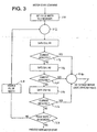
- FIG. 3 there is shown a simplified flow chart for a computer program implemented in controller 42 to provide the ground fault/ground leakage path test of the present invention.
- the switch 12 closes indicating low water pressure and requesting operation of pump motor 40
- the resultant signal indicated as a motor start command
- Controller 42 sets the time duration of an initial set of gating pulses to two microseconds, block 110.
- Controller 42 then sequentially applies a single gating pulse of two microseconds to each of the negative side switching devices (cells) 34, 36 and 38, blocks 112, 114 and 116.
- a time delay is provided during which the current detector circuit is monitored to determine if any current is generated in detector 29 by any one of the gating pulses, blocks 118, 120 and 122. If at any block 118, 120, 122 current is detected, the controller 42 reports a fault condition, block 124. If no current is detected, the program checks to see what pulse width gating pulse was applied, block 126, and, if a two microsecond pulse, steps to block 128 to increase the pulse width and re-run the fault detection test. If no current is detected the second time through the program, the controller 42 again doubles the pulse width and repeats the sequential tests. For the illustrative example, the pulse width is double and testing repeated until the pulse duration is 64 microseconds. However, the pulse width is determined by characteristics of the load and circuit and may be set for more or less than 64 microseconds. Once the tests have been completed successfully, the controller exits the sub-routine and proceeds with normal motor start.
- FIG. 3 suggests that a two microsecond gating pulse is preferable, it will be recognized that the pulse duration is a function of the system characteristics and the switching device operation. Similarly, for high impedance faults, a pulse width greater than four microseconds may be desirable. In general, it is believed that an exemplary system will require a pulse width which does not exceed about one millisecond. Further, while two steps are used to identify high and low impedance faults, it may be preferable to use more than two steps, particularly where the first two sets of gating pulses are two and four microseconds in duration. For example, a third step using a one millisecond gating pulse might be useful in identifying very high impedance leakage paths.
- ground detection circuitry is used for personnel safety considerations and must be able to detect leakage currents which are less than the magnitude considered to be lethal.
- This system is not intended to function as a safety device, but rather as a protective device to prevent damage to the unit should leakage to ground occur. If a ground exists and the contractor fails to check for grounds before energizing the system, the controller will be damaged and require replacement. Should he fail to realize that the cause of the failure is a ground in the system, he may install and similarly destroy a replacement. Thus it becomes important to incorporate some form of protection against failures induced by ground faults.
Landscapes
- Engineering & Computer Science (AREA)
- Power Engineering (AREA)
- Physics & Mathematics (AREA)
- General Physics & Mathematics (AREA)
- Mechanical Engineering (AREA)
- General Engineering & Computer Science (AREA)
- Control Of Ac Motors In General (AREA)
- Inverter Devices (AREA)
- Testing Of Short-Circuits, Discontinuities, Leakage, Or Incorrect Line Connections (AREA)
- Emergency Protection Circuit Devices (AREA)
- Electric Propulsion And Braking For Vehicles (AREA)
Applications Claiming Priority (2)
| Application Number | Priority Date | Filing Date | Title |
|---|---|---|---|
| US08/966,289 US5945802A (en) | 1996-09-27 | 1997-11-07 | Ground fault detection and protection method for a variable speed ac electric motor |
| US966289 | 1997-11-07 |
Publications (3)
| Publication Number | Publication Date |
|---|---|
| EP0915348A2 EP0915348A2 (en) | 1999-05-12 |
| EP0915348A3 EP0915348A3 (en) | 2001-12-12 |
| EP0915348B1 true EP0915348B1 (en) | 2006-01-04 |
Family
ID=25511170
Family Applications (1)
| Application Number | Title | Priority Date | Filing Date |
|---|---|---|---|
| EP98309056A Expired - Lifetime EP0915348B1 (en) | 1997-11-07 | 1998-11-05 | Ground fault detection and protection method for a variable speed ac electric motor |
Country Status (4)
| Country | Link |
|---|---|
| US (1) | US5945802A (enExample) |
| EP (1) | EP0915348B1 (enExample) |
| JP (1) | JP4012637B2 (enExample) |
| DE (1) | DE69833097T2 (enExample) |
Cited By (2)
| Publication number | Priority date | Publication date | Assignee | Title |
|---|---|---|---|---|
| KR20140026107A (ko) * | 2012-08-24 | 2014-03-05 | 현대모비스 주식회사 | 스위칭 소자 쇼트 검출 장치 및 방법 |
| WO2017127112A1 (en) * | 2016-01-22 | 2017-07-27 | Halliburton Energy Services, Inc. | Solid state protection circuits |
Families Citing this family (81)
| Publication number | Priority date | Publication date | Assignee | Title |
|---|---|---|---|---|
| DE19837796A1 (de) * | 1998-08-20 | 2000-02-24 | Wilo Gmbh | Verfahren zur Ermittlung des Pumpenzustandes |
| US6327124B1 (en) * | 1999-02-05 | 2001-12-04 | Smc Electrical Products, Inc. | Low current ground fault relay |
| GB0000864D0 (en) * | 2000-01-15 | 2000-03-08 | Lucas Industries Ltd | Power supply refresh control |
| US6427540B1 (en) * | 2000-02-15 | 2002-08-06 | Breed Automotive Technology, Inc. | Pressure sensor system and method of excitation for a pressure sensor |
| KR20000036351A (ko) * | 2000-02-19 | 2000-07-05 | 정현오 | 무선 자동 수위 조절시스템 |
| US6499961B1 (en) * | 2000-03-16 | 2002-12-31 | Tecumseh Products Company | Solid state liquid level sensor and pump controller |
| US6718474B1 (en) | 2000-09-21 | 2004-04-06 | Stratus Technologies Bermuda Ltd. | Methods and apparatus for clock management based on environmental conditions |
| US6531842B2 (en) * | 2001-06-25 | 2003-03-11 | Schlumberger Technology Corp. | Sine wave variable speed drive |
| JP2003102180A (ja) * | 2001-09-21 | 2003-04-04 | Hitachi Ltd | 電車用モジュール形インバータ装置 |
| JP2003176788A (ja) * | 2001-12-10 | 2003-06-27 | Matsushita Electric Ind Co Ltd | リニアコンプレッサの駆動装置 |
| US6856137B2 (en) * | 2002-02-19 | 2005-02-15 | Bae Systems Controls Inc. | Ground fault detection system and method |
| US7746604B2 (en) * | 2002-04-02 | 2010-06-29 | General Electric Company | Method, system, and computer software code for detection and isolation of electrical ground failure and secondary failure |
| US7035065B2 (en) * | 2002-04-02 | 2006-04-25 | General Electric Company | Electrical ground isolation and secondary failure reduction detection and isolation |
| US6762920B2 (en) * | 2002-04-30 | 2004-07-13 | Eaton Corporation | Electronic fault detector for variable frequency ac systems and circuit breaker incorporating same |
| KR100505049B1 (ko) * | 2003-03-26 | 2005-08-03 | 엘에스산전 주식회사 | 인버터의 고장진단 방법 |
| EP1501186B1 (en) * | 2003-07-18 | 2018-08-22 | III Holdings 10, LLC | Motor driving apparatus |
| DE10336604A1 (de) * | 2003-08-08 | 2005-03-03 | BSH Bosch und Siemens Hausgeräte GmbH | Verfahren und Schaltungsanordnung zur Überwachung der Funktionsweise eines oder mehrerer Verbraucherstromkreise, insbesondere eines Hausgeräts |
| US8540493B2 (en) | 2003-12-08 | 2013-09-24 | Sta-Rite Industries, Llc | Pump control system and method |
| US8019479B2 (en) | 2004-08-26 | 2011-09-13 | Pentair Water Pool And Spa, Inc. | Control algorithm of variable speed pumping system |
| US8480373B2 (en) | 2004-08-26 | 2013-07-09 | Pentair Water Pool And Spa, Inc. | Filter loading |
| US7845913B2 (en) | 2004-08-26 | 2010-12-07 | Pentair Water Pool And Spa, Inc. | Flow control |
| US8469675B2 (en) | 2004-08-26 | 2013-06-25 | Pentair Water Pool And Spa, Inc. | Priming protection |
| US7874808B2 (en) | 2004-08-26 | 2011-01-25 | Pentair Water Pool And Spa, Inc. | Variable speed pumping system and method |
| US7854597B2 (en) | 2004-08-26 | 2010-12-21 | Pentair Water Pool And Spa, Inc. | Pumping system with two way communication |
| US8602745B2 (en) | 2004-08-26 | 2013-12-10 | Pentair Water Pool And Spa, Inc. | Anti-entrapment and anti-dead head function |
| US7686589B2 (en) | 2004-08-26 | 2010-03-30 | Pentair Water Pool And Spa, Inc. | Pumping system with power optimization |
| JP4554501B2 (ja) * | 2005-01-18 | 2010-09-29 | ファナック株式会社 | モータの絶縁抵抗劣化検出方法、絶縁抵抗劣化検出装置およびモータ駆動装置 |
| US7489105B2 (en) * | 2005-03-21 | 2009-02-10 | Eveready Battery Company, Inc. | Portable power supply |
| US7344202B2 (en) * | 2005-05-11 | 2008-03-18 | General Electric Company | System and method for dealing with ground fault conditions that can arise in an electrical propulsion system |
| US8193745B2 (en) * | 2005-05-13 | 2012-06-05 | Schlumberger Technology Corporation | Filtering and boosting a signal from a drive circuit |
| US7498819B2 (en) * | 2006-03-21 | 2009-03-03 | General Electric Company | Method, apparatus and computer-readable code for detecting an incipient ground fault in an electrical propulsion system |
| US7501830B2 (en) * | 2006-03-21 | 2009-03-10 | General Electric Company | Method, apparatus and computer-readable code for detecting an incipient ground fault in an electrical propulsion system |
| US7498820B2 (en) * | 2006-03-21 | 2009-03-03 | General Electric Company | Method, apparatus and computer-readable code for detecting an incipient ground fault in an electrical propulsion system |
| US7248057B1 (en) | 2006-03-21 | 2007-07-24 | General Electric Company | Method, apparatus and computer-readable code for detecting on the fly an incipient ground fault in an electrical propulsion system of a locomotive |
| US7102355B1 (en) | 2006-03-21 | 2006-09-05 | General Electric Company | Method, apparatus and computer-readable code for magnifying an incipient ground fault and enable quick detection of such fault |
| CA2671353C (en) | 2006-08-04 | 2014-04-22 | Direct Drive Pcp Inc. | A motor direct drive rod ground screw pump device |
| US7489483B2 (en) * | 2006-09-19 | 2009-02-10 | Flextronics Automotive Inc. | System and method for look ahead detection of electrical problems at a motor of a vehicle |
| KR101403349B1 (ko) * | 2006-12-05 | 2014-06-05 | 신에쯔 세끼에이 가부시키가이샤 | 합성 불투명 석영유리 및 그 제조방법 |
| US7805204B2 (en) * | 2007-03-21 | 2010-09-28 | Honeywell International Inc. | Integrated electrical power distribution system using common building blocks |
| US8050806B2 (en) * | 2007-03-21 | 2011-11-01 | Honeywell International Inc. | Ground fault interruption using DSP based SSPC module |
| EP2028756A1 (en) * | 2007-08-23 | 2009-02-25 | Siemens Aktiengesellschaft | An Inverter With Short Circuit Protection |
| US7978446B2 (en) * | 2008-02-29 | 2011-07-12 | Caterpillar Inc. | High voltage ground fault detection system |
| AU2009302593B2 (en) | 2008-10-06 | 2015-05-28 | Danfoss Low Power Drives | Method of operating a safety vacuum release system |
| US8149551B2 (en) * | 2009-04-09 | 2012-04-03 | Hamilton Sundstrand Corporation | Systems and methods involving motor drive ground fault interrupts |
| US8436559B2 (en) * | 2009-06-09 | 2013-05-07 | Sta-Rite Industries, Llc | System and method for motor drive control pad and drive terminals |
| US9556874B2 (en) | 2009-06-09 | 2017-01-31 | Pentair Flow Technologies, Llc | Method of controlling a pump and motor |
| US8564233B2 (en) | 2009-06-09 | 2013-10-22 | Sta-Rite Industries, Llc | Safety system and method for pump and motor |
| JP5401250B2 (ja) * | 2009-10-06 | 2014-01-29 | 日立オートモティブシステムズ株式会社 | 地絡検出装置 |
| US8334670B2 (en) * | 2010-03-25 | 2012-12-18 | GM Global Technology Operations LLC | Method and apparatus to monitor an electric motor control circuit |
| US9243413B2 (en) | 2010-12-08 | 2016-01-26 | Pentair Water Pool And Spa, Inc. | Discharge vacuum relief valve for safety vacuum release system |
| US9075099B2 (en) * | 2011-03-03 | 2015-07-07 | Abb Research Ltd. | Method for adaptation of ground fault detection |
| US20140049261A1 (en) * | 2011-04-28 | 2014-02-20 | Aerovironment, Inc. | Pulsed missing ground detector circuit |
| KR20130019911A (ko) * | 2011-08-18 | 2013-02-27 | 현대모비스 주식회사 | 차량용 제동 시스템에서 모터 권선 코일 이상 검출 장치 및 그 방법 |
| JP5846818B2 (ja) * | 2011-09-16 | 2016-01-20 | ミネベア株式会社 | 電力制御装置 |
| JP5726037B2 (ja) * | 2011-09-30 | 2015-05-27 | 三菱電機株式会社 | 半導体装置 |
| BR112014010665A2 (pt) | 2011-11-01 | 2017-12-05 | Pentair Water Pool & Spa Inc | sistema e processo de bloqueio de vazão |
| US11329589B2 (en) * | 2012-03-28 | 2022-05-10 | Joy Global Underground Mining Llc | Ground fault detection methods on variable frequency drive systems |
| JP5505449B2 (ja) * | 2012-04-06 | 2014-05-28 | 株式会社デンソー | 多相回転機の制御装置 |
| US9160161B2 (en) | 2012-05-04 | 2015-10-13 | Eaton Corporation | System and method for ground fault detection and protection in adjustable speed drives |
| US9046560B2 (en) | 2012-06-04 | 2015-06-02 | Eaton Corporation | System and method for high resistance ground fault detection and protection in power distribution systems |
| US9885360B2 (en) | 2012-10-25 | 2018-02-06 | Pentair Flow Technologies, Llc | Battery backup sump pump systems and methods |
| TWI453432B (zh) * | 2012-11-28 | 2014-09-21 | Simplo Technology Co Ltd | 絕緣偵測電路及其方法 |
| WO2014145867A1 (en) * | 2013-03-15 | 2014-09-18 | Pentair Flow Technologies, Llc | Method of controlling a pump and motor |
| US20150102824A1 (en) * | 2013-10-11 | 2015-04-16 | General Electric Company | Locating loose connections in an electrical circuit |
| US9806641B2 (en) * | 2014-11-06 | 2017-10-31 | Rockwell Automation Technologies, Inc. | Detection of electric motor short circuits |
| US10473097B2 (en) | 2015-09-02 | 2019-11-12 | Tigerflow Systems, Llc | System and method for speed control of variable speed pumping systems |
| EP3353882A4 (en) * | 2015-09-22 | 2019-05-08 | Services Petroliers Schlumberger | FAULT TOLERANT INVERTER OR CONTROLLED RECTIFIER SYSTEM |
| US10823516B2 (en) * | 2016-03-14 | 2020-11-03 | Joseph F. Walsh | Ground-detecting descaler |
| WO2017208051A1 (en) * | 2016-05-29 | 2017-12-07 | Aplisens S.A. | Method for diagnosing technical condition of submersible pump unit |
| US10132850B2 (en) | 2016-08-10 | 2018-11-20 | General Electric Company | Electric ground fault detection system and method |
| SE542648C2 (en) * | 2016-10-13 | 2020-06-23 | Husqvarna Ab | Integrated residual current device for handheld wet tools |
| CN107121630A (zh) * | 2017-05-25 | 2017-09-01 | 合肥巨动力系统有限公司 | 一种电机控制系统的主动短路保护电路的自检方法及装置 |
| JP6833638B2 (ja) * | 2017-07-21 | 2021-02-24 | 株式会社東芝 | 電動機用インバータ回路の評価装置および評価方法 |
| US10663531B2 (en) * | 2017-10-11 | 2020-05-26 | Cirrus Logic, Inc. | Digital short detection method of class D amplifier |
| WO2019176299A1 (ja) * | 2018-03-13 | 2019-09-19 | 日立オートモティブシステムズ株式会社 | 車両搭載機器の制御装置 |
| DE102018006355B4 (de) * | 2018-08-11 | 2020-06-10 | Diehl Ako Stiftung & Co. Kg | Verfahren zum Erkennen eines Motorphasenfehlers an einer Motoranordnung und Antriebsschaltung zum Antreiben eines elektronisch kommutierten Motors |
| DE102019121793A1 (de) * | 2018-08-14 | 2020-02-20 | Steering Solutions Ip Holding Corporation | Stromeingangsschaltung mit verbessertem verpolungsschutz zur isolierung der versorgung bei kurzschlussbedingungen und zur verminderung des neustarts des mikrocontrollers aus dem abschaltzustand nach einem fehler |
| US10992147B2 (en) * | 2019-09-25 | 2021-04-27 | GM Global Technology Operations LLC | Diagnostic method for electric propulsion system with reconfigurable battery system |
| CN113471942B (zh) * | 2020-03-30 | 2025-04-11 | 台达电子企业管理(上海)有限公司 | 具有保护电路的电源装置 |
| US12305650B2 (en) | 2020-07-24 | 2025-05-20 | Eaton Intelligent Power Limited | Control system for a fluid management system |
| US20240429789A1 (en) * | 2021-09-21 | 2024-12-26 | Zparq Ab | A method for electric leakage safety of an electric motor, and a protection system |
Family Cites Families (22)
| Publication number | Priority date | Publication date | Assignee | Title |
|---|---|---|---|---|
| US2972708A (en) * | 1956-10-05 | 1961-02-21 | Edward J Schaefer | Protective means for submersible pump-motors |
| US3283236A (en) * | 1965-09-30 | 1966-11-01 | Borg Warner | Control system for power units such as electric motors and the like |
| US3417290A (en) * | 1966-10-24 | 1968-12-17 | Craddock Mike | Oil well pumping unit control circuit |
| US3577052A (en) * | 1968-10-17 | 1971-05-04 | David Elvis Bauer | Ac motor control system with synchronous speed change |
| US4021700A (en) * | 1975-06-04 | 1977-05-03 | Borg-Warner Corporation | Digital logic control system for three-phase submersible pump motor |
| US4000446A (en) * | 1975-06-04 | 1976-12-28 | Borg-Warner Corporation | Overload protection system for three-phase submersible pump motor |
| US3976919A (en) * | 1975-06-04 | 1976-08-24 | Borg-Warner Corporation | Phase sequence detector for three-phase AC power system |
| CH613569A5 (enExample) * | 1977-03-01 | 1979-09-28 | Bbc Brown Boveri & Cie | |
| US4200829A (en) * | 1978-07-12 | 1980-04-29 | General Electric Company | Circuit for protecting induction motors |
| US4242712A (en) * | 1978-10-12 | 1980-12-30 | Lockwood Corporation | Over-power safety device for motor driven system |
| US4284943A (en) * | 1979-02-13 | 1981-08-18 | Electric Machinery Mfg. Company | Apparatus and method for controlling the speed of an induction motor in a closed-loop system |
| NL8202259A (nl) * | 1982-06-04 | 1984-01-02 | Philips Nv | Voedingsstelsel omvattende een wisselspanning-voedingsbron, een belasting en een verbindingskabel tussen bron en belasting. |
| US4618810A (en) * | 1983-02-04 | 1986-10-21 | Emerson Electric Company | Variable speed AC motor control system |
| DE3436776A1 (de) * | 1984-10-06 | 1986-04-10 | Teldix Gmbh, 6900 Heidelberg | Ueberwachungseinrichtung insbesondere fuer einen kollektorlosen gleichstrommotor |
| US4716487A (en) * | 1986-05-05 | 1987-12-29 | Automeg, Inc. | Apparatus for monitoring motor winding leakage |
| JP2714449B2 (ja) * | 1989-08-08 | 1998-02-16 | 株式会社日立製作所 | 可変速ポンプシステム |
| US5386183A (en) * | 1990-01-03 | 1995-01-31 | Siemens Energy & Automation, Inc. | Method and apparatus for sensing a ground fault in a motor control system |
| US5350992A (en) * | 1991-09-17 | 1994-09-27 | Micro-Trak Systems, Inc. | Motor control circuit |
| JP2903863B2 (ja) * | 1992-05-29 | 1999-06-14 | 三菱電機株式会社 | インバータ装置 |
| DE4329382A1 (de) * | 1993-09-01 | 1995-03-02 | Abb Management Ag | Verfahren und Vorrichtung zur Erfassung von Erdfehlern auf den Leitern einer elektrischen Maschine |
| JPH07239359A (ja) * | 1994-02-25 | 1995-09-12 | Mitsubishi Electric Corp | インバータ装置及びその運転方法 |
| US5580221A (en) * | 1994-10-05 | 1996-12-03 | Franklin Electric Co., Inc. | Motor drive circuit for pressure control of a pumping system |
-
1997
- 1997-11-07 US US08/966,289 patent/US5945802A/en not_active Expired - Lifetime
-
1998
- 1998-10-29 JP JP30770598A patent/JP4012637B2/ja not_active Expired - Lifetime
- 1998-11-05 DE DE69833097T patent/DE69833097T2/de not_active Expired - Lifetime
- 1998-11-05 EP EP98309056A patent/EP0915348B1/en not_active Expired - Lifetime
Cited By (3)
| Publication number | Priority date | Publication date | Assignee | Title |
|---|---|---|---|---|
| KR20140026107A (ko) * | 2012-08-24 | 2014-03-05 | 현대모비스 주식회사 | 스위칭 소자 쇼트 검출 장치 및 방법 |
| WO2017127112A1 (en) * | 2016-01-22 | 2017-07-27 | Halliburton Energy Services, Inc. | Solid state protection circuits |
| US11133664B2 (en) | 2016-01-22 | 2021-09-28 | Halliburton Energy Services, Inc. | Solid state protection circuits for a converter circuit |
Also Published As
| Publication number | Publication date |
|---|---|
| US5945802A (en) | 1999-08-31 |
| EP0915348A2 (en) | 1999-05-12 |
| DE69833097D1 (de) | 2006-03-30 |
| DE69833097T2 (de) | 2006-08-31 |
| EP0915348A3 (en) | 2001-12-12 |
| JP4012637B2 (ja) | 2007-11-21 |
| JPH11235047A (ja) | 1999-08-27 |
Similar Documents
| Publication | Publication Date | Title |
|---|---|---|
| EP0915348B1 (en) | Ground fault detection and protection method for a variable speed ac electric motor | |
| JP4012604B2 (ja) | 交流電動機のトルクを制御する方法 | |
| US4486801A (en) | Generator shorted diode protection system | |
| CA2285683C (en) | Method and apparatus for controlling operation of a submersible pump | |
| EP0166052B1 (en) | Method and system for reconnecting inverter to rotating motors | |
| US11506195B2 (en) | Method and system for controlling downhole pumping systems | |
| US6429612B1 (en) | Fast stopping method for induction motors operating from variable frequency drives | |
| US4100469A (en) | Hybrid motor starter | |
| EP1131873B1 (en) | A system and a method for protecting an electric motor and its control circuit, and an electric motor | |
| US4594632A (en) | Overvoltage protection circuit for synchronous machinerotor | |
| US6008602A (en) | Arrangement with an electronically commutated motor | |
| WO1998027641A1 (fr) | Circuit de protection contre les surtensions pour convertisseur abaisseur | |
| CN111817620A (zh) | 保护装置 | |
| RU2219650C2 (ru) | Станция управления асинхронным двигателем | |
| CN113424431A (zh) | 具有逆变器和电机的驱动系统和用于运行驱动系统的方法 | |
| JP3287020B2 (ja) | 2次励磁装置 | |
| EP0194400A1 (en) | A method of starting an asynchronous motor and an apparatus for carrying said method into effect | |
| JPH07289766A (ja) | 工業用ミシン駆動装置 | |
| EP1215793A2 (en) | Transient voltage suppression | |
| JP6596358B2 (ja) | 界磁巻線型同期電動機 | |
| RU22843U1 (ru) | Станция управления асинхронным двигателем | |
| JPH0126251B2 (enExample) | ||
| JPH10239360A (ja) | 過電流検出回路 | |
| KR200157527Y1 (ko) | 유도전동기구동시스템에서의 컨버터고장검출장치 | |
| KR910006300Y1 (ko) | 인버터 출력전류의 상간 억제 제어장치 |
Legal Events
| Date | Code | Title | Description |
|---|---|---|---|
| PUAI | Public reference made under article 153(3) epc to a published international application that has entered the european phase |
Free format text: ORIGINAL CODE: 0009012 |
|
| AK | Designated contracting states |
Kind code of ref document: A2 Designated state(s): AT BE CH CY DE DK ES FI FR GB GR IE IT LI LU MC NL PT SE Kind code of ref document: A2 Designated state(s): DE FR GB IT |
|
| AX | Request for extension of the european patent |
Free format text: AL;LT;LV;MK;RO;SI |
|
| PUAL | Search report despatched |
Free format text: ORIGINAL CODE: 0009013 |
|
| AK | Designated contracting states |
Kind code of ref document: A3 Designated state(s): AT BE CH CY DE DK ES FI FR GB GR IE IT LI LU MC NL PT SE |
|
| AX | Request for extension of the european patent |
Free format text: AL;LT;LV;MK;RO;SI |
|
| 17P | Request for examination filed |
Effective date: 20020612 |
|
| AKX | Designation fees paid |
Free format text: DE FR GB IT |
|
| 17Q | First examination report despatched |
Effective date: 20030918 |
|
| GRAP | Despatch of communication of intention to grant a patent |
Free format text: ORIGINAL CODE: EPIDOSNIGR1 |
|
| GRAS | Grant fee paid |
Free format text: ORIGINAL CODE: EPIDOSNIGR3 |
|
| GRAA | (expected) grant |
Free format text: ORIGINAL CODE: 0009210 |
|
| AK | Designated contracting states |
Kind code of ref document: B1 Designated state(s): DE FR GB IT |
|
| PG25 | Lapsed in a contracting state [announced via postgrant information from national office to epo] |
Ref country code: IT Free format text: LAPSE BECAUSE OF FAILURE TO SUBMIT A TRANSLATION OF THE DESCRIPTION OR TO PAY THE FEE WITHIN THE PRESCRIBED TIME-LIMIT;WARNING: LAPSES OF ITALIAN PATENTS WITH EFFECTIVE DATE BEFORE 2007 MAY HAVE OCCURRED AT ANY TIME BEFORE 2007. THE CORRECT EFFECTIVE DATE MAY BE DIFFERENT FROM THE ONE RECORDED. Effective date: 20060104 |
|
| REG | Reference to a national code |
Ref country code: GB Ref legal event code: FG4D |
|
| REF | Corresponds to: |
Ref document number: 69833097 Country of ref document: DE Date of ref document: 20060330 Kind code of ref document: P |
|
| ET | Fr: translation filed | ||
| PLBE | No opposition filed within time limit |
Free format text: ORIGINAL CODE: 0009261 |
|
| STAA | Information on the status of an ep patent application or granted ep patent |
Free format text: STATUS: NO OPPOSITION FILED WITHIN TIME LIMIT |
|
| 26N | No opposition filed |
Effective date: 20061005 |
|
| REG | Reference to a national code |
Ref country code: FR Ref legal event code: PLFP Year of fee payment: 18 |
|
| REG | Reference to a national code |
Ref country code: FR Ref legal event code: PLFP Year of fee payment: 19 |
|
| REG | Reference to a national code |
Ref country code: FR Ref legal event code: PLFP Year of fee payment: 20 |
|
| PGFP | Annual fee paid to national office [announced via postgrant information from national office to epo] |
Ref country code: FR Payment date: 20171127 Year of fee payment: 20 Ref country code: DE Payment date: 20171129 Year of fee payment: 20 |
|
| PGFP | Annual fee paid to national office [announced via postgrant information from national office to epo] |
Ref country code: GB Payment date: 20171127 Year of fee payment: 20 Ref country code: IT Payment date: 20171123 Year of fee payment: 20 |
|
| REG | Reference to a national code |
Ref country code: DE Ref legal event code: R071 Ref document number: 69833097 Country of ref document: DE |
|
| REG | Reference to a national code |
Ref country code: GB Ref legal event code: PE20 Expiry date: 20181104 |
|
| PG25 | Lapsed in a contracting state [announced via postgrant information from national office to epo] |
Ref country code: GB Free format text: LAPSE BECAUSE OF EXPIRATION OF PROTECTION Effective date: 20181104 |