EP0915278B1 - Ventildichtungsanordnung - Google Patents
Ventildichtungsanordnung Download PDFInfo
- Publication number
- EP0915278B1 EP0915278B1 EP98120761A EP98120761A EP0915278B1 EP 0915278 B1 EP0915278 B1 EP 0915278B1 EP 98120761 A EP98120761 A EP 98120761A EP 98120761 A EP98120761 A EP 98120761A EP 0915278 B1 EP0915278 B1 EP 0915278B1
- Authority
- EP
- European Patent Office
- Prior art keywords
- valve
- closure member
- sealing element
- sealing
- annular
- Prior art date
- Legal status (The legal status is an assumption and is not a legal conclusion. Google has not performed a legal analysis and makes no representation as to the accuracy of the status listed.)
- Expired - Lifetime
Links
- 238000007789 sealing Methods 0.000 claims abstract description 46
- XLYOFNOQVPJJNP-UHFFFAOYSA-N water Substances O XLYOFNOQVPJJNP-UHFFFAOYSA-N 0.000 description 6
- 238000000034 method Methods 0.000 description 3
- 239000011324 bead Substances 0.000 description 1
- 229920001971 elastomer Polymers 0.000 description 1
- 239000000806 elastomer Substances 0.000 description 1
- 239000003292 glue Substances 0.000 description 1
- 238000001746 injection moulding Methods 0.000 description 1
- 230000000284 resting effect Effects 0.000 description 1
- 238000011144 upstream manufacturing Methods 0.000 description 1
Images
Classifications
-
- E—FIXED CONSTRUCTIONS
- E03—WATER SUPPLY; SEWERAGE
- E03D—WATER-CLOSETS OR URINALS WITH FLUSHING DEVICES; FLUSHING VALVES THEREFOR
- E03D1/00—Water flushing devices with cisterns ; Setting up a range of flushing devices or water-closets; Combinations of several flushing devices
- E03D1/30—Valves for high or low level cisterns; Their arrangement ; Flushing mechanisms in the cistern, optionally with provisions for a pre-or a post- flushing and for cutting off the flushing mechanism in case of leakage
- E03D1/34—Flushing valves for outlets; Arrangement of outlet valves
-
- E—FIXED CONSTRUCTIONS
- E03—WATER SUPPLY; SEWERAGE
- E03D—WATER-CLOSETS OR URINALS WITH FLUSHING DEVICES; FLUSHING VALVES THEREFOR
- E03D3/00—Flushing devices operated by pressure of the water supply system flushing valves not connected to the water-supply main, also if air is blown in the water seal for a quick flushing
- E03D3/02—Self-closing flushing valves
-
- F—MECHANICAL ENGINEERING; LIGHTING; HEATING; WEAPONS; BLASTING
- F16—ENGINEERING ELEMENTS AND UNITS; GENERAL MEASURES FOR PRODUCING AND MAINTAINING EFFECTIVE FUNCTIONING OF MACHINES OR INSTALLATIONS; THERMAL INSULATION IN GENERAL
- F16K—VALVES; TAPS; COCKS; ACTUATING-FLOATS; DEVICES FOR VENTING OR AERATING
- F16K39/00—Devices for relieving the pressure on the sealing faces
- F16K39/02—Devices for relieving the pressure on the sealing faces for lift valves
- F16K39/022—Devices for relieving the pressure on the sealing faces for lift valves using balancing surfaces
Definitions
- the invention relates to a valve seal arrangement, especially for a cistern drain valve or a Self-closing valve, with a closure member on which radially protruding an annular sealing element in a Ring groove is held, which on the other hand on a valve seat larger in diameter in the shut-off position comes to the plant.
- valve seal arrangements are known (See, for example, patent documents DE-A-1 914 064 and FR-A-2 343 092). This has been particularly the case with cistern drain valves shown that on the annular surface of the valve closure member acting water column an undesirable high level of force when opening the drain valve requires. Even with self-closing valves with one Pressure chamber for a main valve closure member, wherein a rod-shaped to control the main valve closure member Relief valve to be operated by the user is used, it can become an undesirable Relief valve stiffness come when the rod-shaped relief valve at the same time Actuator for the self-closing valve carries and must have correspondingly large dimensions.
- the invention is therefore based on the object to create generic valve seal arrangement, with the one required for valve actuation Force application can be reduced.
- an overflow channel or several overflow channels is or are formed in the region of the annular groove and the sealing element is held axially slightly movable to the sealing edge on the closure member, with a throttle channel or a plurality of throttle channels being formed downstream of the sealing element , whose or their total flow cross-section is smaller than that of the overflow channel or the overflow channels.
- a bead-shaped circumferential valve seat 2 is provided, against which a sealing element 3 made of elastomer, which is designed as a flat ring, rests in the closed position.
- the sealing element 3 is supported on the rear on a valve closure member 1 formed on an overflow pipe 5 on a circumferential sealing edge 11.
- a circumferential annular groove 10 is formed in the valve closure member 1, from which the annular element 3 is accommodated in a slightly displaceable manner on the inner region.
- ribs 101 are formed corresponding to the U-profile of the annular groove, which delimit overflow channels 100 arranged approximately symmetrically.
- an annular extension 50 is provided in the area of the valve closure member 1, so that the annular groove 10 with the ribs 101 can be produced in a relatively simple manner by injection molding.
- the ring extension 50 is produced separately and finally applied to the overflow pipe, it being possible, for example, to weld, glue or screw it on.
- the downstream end region of the ring extension 50 also forms an annular throttle duct 4 with the wall of the outlet opening 20 of the valve seat 2.
- the cross section of the throttle duct 4 is designed to be smaller than the cross section of the overflow ducts 100.
- the cistern drain valve described above works as follows: In the left half of the picture the drain valve is in the closed position.
- the sealing element 3 lies here in a sealing manner on the annular valve seat 2.
- the sealing edge 11 which is designed as a circumferential bead, bears against the sealing element 3, so that water cannot pass from an annular space 21 in the cistern into the outlet opening 20.
- a slight water column with the thickness A acts on the closure member 11, while an annular water column with the thickness C acts on the sealing element 3.
- a pressure relief valve of a self-closing valve wherein a main valve closure member 6 is displaceably arranged piston-shaped in a valve housing, not shown, which is pressed into its closed position by a pressure chamber 60, the pressure chamber 60 via a throttle nozzle (in the Drawing not shown) is acted upon by the pressure prevailing upstream of the main valve.
- a rod-shaped valve closure member 1 is provided in the main valve closure member 6 with an O-ring-shaped sealing element 3 for pressure relief, which in the closed position rests against a conical valve seat 2 of the main valve closure member 6.
- the sealing element 3 lies on the opposite side against a sealing edge 11 of the valve closure member 1, an annular groove 10 being formed in the rod-shaped valve closure member 1, in which the sealing element 3 is held slightly axially displaceably.
- Overflow channels 100 are formed on the side opposite the sealing edge 11 and in the base of the annular groove 10.
- throttle channels 4 are formed downstream behind the sealing element 3. The cross section of the throttle channels 4 is limited here by the cylindrical outer surface of the rod-shaped closure member 1 and axial grooves in the wall of a guide bore in the main valve closure member 6 for the downstream end region of the rod-shaped closure member 1.
- the relief valve described above works as follows: In the left half of the figure, the relief valve is shown in the closed position, the sealing element 3 resting on the one hand on the conical surface of the valve seat 2 which is larger in diameter than the valve closure member 1, while it rests on the valve closure member 1 on the sealing edge 11 and thus a pressure relief from the pressure chamber Shuts off 60 in the throttle channel 4.
Landscapes
- Engineering & Computer Science (AREA)
- General Engineering & Computer Science (AREA)
- Life Sciences & Earth Sciences (AREA)
- Hydrology & Water Resources (AREA)
- Public Health (AREA)
- Water Supply & Treatment (AREA)
- Health & Medical Sciences (AREA)
- Mechanical Engineering (AREA)
- Safety Valves (AREA)
- Lift Valve (AREA)
- Glass Compositions (AREA)
- Fluid-Driven Valves (AREA)
- Temperature-Responsive Valves (AREA)
Description
Weitere Ausgestaltungen der Erfindung sind in den Ansprüchen 2 bis 4 angegeben.
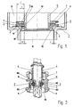
- Fig. 1
- ein teilweise dargestelltes Spülkastenablaufventil im Längsschnitt, wobei in der linken Bildhälfte das Ventil in Absperrstellung, in der rechten Bildhälfte das Ventil am Beginn des Öffnungsvorgangs dargestellt ist;
- Fig. 2
- ein Entlastungsventil für ein Selbstschlußventil im Längsschnitt, wobei in der linken Hälfte das Entlastungsventil in der Schließstellung, in der rechten Bildhälfte der Beginn der Öffnungsstellung dargestellt ist.
Bei dem in Fig. 1 gezeigten Spülkastenablaufventil ist ein wulstförmig umlaufender Ventilsitz 2 vorgesehen, an dem ein als Flachring ausgebildetes Dichtelement 3 aus Elastomer in der Schließstellung anliegt. Das Dichtelement 3 stützt sich hierbei an der Rückseite an einem an einem Überlaufrohr 5 ausgebildeten Ventilverschlußglied 1 an einer umlaufenden Dichtkante 11 ab. In dem Ventilverschlußglied 1 ist eine umlaufende Ringnut 10 ausgebildet, von der das ringförmige Element 3 an dem Innenbereich geringförmig verschieblich aufgenommen ist. In der Ringnut 10 sind entsprechend dem U-Profil der Ringnut Rippen 101 ausgebildet, die etwa symmetrisch angeordnete Überströmkanäle 100 begrenzen. Am stromabwärts gelegenen Ende des Überlaufrohrs 5 ist im Bereich des Ventilverschlußglieds 1 ein Ringfortsatz 50 vorgesehen, so daß eine relativ einfache Herstellung der Ringnut 10 mit den Rippen 101 im Spritzgießverfahren erfolgen kann. Der Ringfortsatz 50 wird separat hergestellt und abschließend auf das Überlaufrohr aufgebracht, wobei er beispielsweise angeschweißt, angeklebt oder aufgeschraubt werden kann. Der stromabwärts gelegene Endbereich des Ringfortsatzes 50 bildet außerdem mit der Wandung der Auslaßöffnung 20 des Ventilsitzes 2 einen ringförmigen Drosselkanal 4. Der Querschnitt des Drosselkanals 4 ist dabei kleiner ausgelegt als der Querschnitt der Überströmkanäle 100.
In der linken Bildhälfte befindet sich das Ablaufventil in der Schließstellung. Das Dichtelement 3 liegt hierbei auf dem ringförmigen Ventilsitz 2 abdichtend auf. An der gegenüberliegenden Seite des Dichtelements 3 liegt die als umlaufender Wulst ausgebildete Dichtkante 11 an dem Dichtelement 3 an, so daß ein Wasserdurchtritt von einem Ringraum 21 im Spülkasten in die Auslaßöffnung 20 verhindert ist. Hierbei wirkt eine geringförmige Wassersäule mit der Dicke A auf das Verschlußglied 1 1 ein, während auf das Dichtelement 3 eine Ringwassersäule mit der Dicke C einwirkt.
Wird nun vom Benutzer das Überlaufrohr 5 angehoben, so wird zunächst lediglich das Ventilverschlußglied 1 von dem Dichtelement 3 abgehoben, so daß das Wasser im Bereich der Dichtkante in die Überströmkanäle 100 einströmt und an dem im Querschnitt kleiner gehaltenen Drosselkanal 4 in die Auslaßöffnung 20 austritt. Hierbei bildet sich ein ringförmig ausgebildeter Staudruck, so daß im wesentlichen lediglich nur noch die ringförmige Wassersäule mit der Dicke B am weiteren Öffnungsvorgäng angehoben werden muß, um das Dichtelement 3 vom Ventilsitz 2 zu lösen und die volle Öffnung des Ablaufventils zu erwirken.
In dem in Fig. 2 gezeigten Ausführungsbeispiel ist ein Druckentlastungsventil eines Selbstschlußventils dargestellt, wobei ein Hauptventilverschlußglied 6 kolbenförmig verschiebbar in einem nicht gezeigten Ventilgehäuse angeordnet ist, das von einer Druckkammer 60 in seine Schließposition gedrückt wird, wobei die Druckkammer 60 über eine Drosseldüse (in der Zeichnung nicht dargestellt) mit dem stromaufwärts vor dem Hauptventil herrschenden Druck beaufschlagt ist. Zur Öffnung des Selbstschlußventils ist hierbei in dem Hauptventilverschlußglied 6 ein stangenförmig ausgebildetes Ventilverschlußglied 1 mit einem O-ringförmigen Dichtelement 3 zur Druckentlastung vorgesehen, welches in der Schließposition an einem kegelförmig ausgebildeten Ventilsitz 2 des Hauptventilverschlußglieds 6 anliegt. Das Dichtelement 3 liegt an der entgegengesetzten Seite an einer Dichtkante 11 des Ventilverschlußglieds 1 an, wobei in dem stangenförmigen Ventilverschlußglied 1 eine Ringnut 10 ausgebildet ist, in der das Dichtelement 3 geringfügig axial verschieblich gehalten ist. An der der Dichtkante 11 gegenüberliegenden Seite und im Grund der Ringnut 10 sind Überströmkanäle 100 ausgebildet. Außerdem sind stromabwärts hinter dem Dichtelement 3 Drosselkanäle 4 ausgebildet. Der Querschnitt der Drosselkanäle 4 wird hierbei von der zylindrischen Mantelfläche des stangenförmigen Verschlußglieds 1 und Axialnuten in der Wandung einer Führungsbohrung im Hauptventilverschlußglied 6 für den stromabwärts gelegenen Endbereich des stangenförmigen Verschlußglieds 1 begrenzt.
In der linken Bildhälfte ist das Entlastungsventil in der Schließstellung gezeigt, wobei das Dichtelement 3 einerseits an der im Durchmesser größer als das Ventilverschlußglied 1 ausgebildeten Kegelfläche des Ventilsitzes 2 anliegt, während es am Ventilverschlußglied 1 an der Dichtkante 11 anliegt und somit eine Druckentlastung aus der Druckkammer 60 in den Drosselkanal 4 absperrt.
Claims (4)
- Ventildichtungsanordnung, insbesondere für ein Spülkastenablaufventil oder ein Selbstschlußventil, mit einem Ventilsitz (2) und mit einem Verschlußglied (1), an dem radial vorstehend ein ringförmiges Dichtelement (3) in einer Ringnut (10) gehalten ist, welches andererseits an dem im Durchmesser größeren Ventilsitz (2) in der Absperrposition zur Anlage gelangt, dadurch gekennzeichnet, daß im Bereich der Ringnut (10) ein Überströmkanal oder mehrere Überströmkanäle (100) ausgebildet ist oder sind und das Dichtelement (3) axial geringfügig beweglich zur Dichtkante (11) am Ventilverschlußglied (1) gehalten ist, wobei stromabwärts hinter dem Dichtelement (3) ein Drosselkanal oder mehrere Drosselkanäle (4) ausgebildet ist oder sind, dessen oder deren Gesamtströmungsquerschnitt kleiner als der des Überströmkanals oder der Überströmkanäle (100) ist, und wobei der Durchmesser der Dichtkante (11) an Ventilverschlußglied (1) geringer ist als der Durchmesser des Ventilsitzes (2).
- Ventildichtungsanordnung nach Anspruch 1, dadurch gekennzeichnet, daß das Verschlußglied (1) an einem Überlaufrohr (5) eines Spülkastenablaufventils ausgebildet und als Dichtelement (3) eine Ringscheibe vorgesehen ist, wobei in der Ringnut (10) zur Bildung der Überströmkanäle (100) radial verlaufende U-förmig gebildete Rippen (101) vorgesehen sind, und die Dichtkante (11) von einem umlaufenden Wulst des Verschlußglieds (1) gebildet ist, während der Drosselkanal (4) von einem in einer Auslaßöffnung (20) in der Schließstellung einfassenden Ringfortsatz (50) des Überlaufrohrs (5) gebildet ist.
- Ventildichtungsanordnung nach Anspruch 2, dadurch gekennzeichnet, daß der Ringfortsatz (50) die stromabwärts liegende Seitenwand mit deren Rippen (101) bildet, wobei der Ringfortsatz (50) axial auf das Überlaufrohr (5) aufbring- und befestigbar ist.
- Ventildichtungsanordnung nach Anspruch 1, dadurch gekennzeichnet, daß das Ventilverschlußglied (1) stangenförmig als Druckentlastungsventil für ein Selbstschlußventil ausgebildet ist, wobei die Dichtkante (11), an der der Druckseite zugekehrten Seitenwand der Ringnut (10) vorgesehen ist und die Überströmkanäle (100) im Grund und in der der Druckseite abgekehrten Seite ausgebildet sind, während der Drosselkanal (4) von der zylindrischen Außenseite des stangenförmigen Ventilverschlußglieds (1) und Axialnuten in der Wandung einer Führungsbohrung in einem kolbenförmigen Hauptventilverschlußglied (6) begrenzt ist.
Applications Claiming Priority (2)
| Application Number | Priority Date | Filing Date | Title |
|---|---|---|---|
| DE19748620A DE19748620A1 (de) | 1997-11-04 | 1997-11-04 | Ventildichtungsanordnung |
| DE19748620 | 1997-11-04 |
Publications (2)
| Publication Number | Publication Date |
|---|---|
| EP0915278A1 EP0915278A1 (de) | 1999-05-12 |
| EP0915278B1 true EP0915278B1 (de) | 2003-10-01 |
Family
ID=7847537
Family Applications (1)
| Application Number | Title | Priority Date | Filing Date |
|---|---|---|---|
| EP98120761A Expired - Lifetime EP0915278B1 (de) | 1997-11-04 | 1998-11-02 | Ventildichtungsanordnung |
Country Status (5)
| Country | Link |
|---|---|
| EP (1) | EP0915278B1 (de) |
| AT (1) | ATE251283T1 (de) |
| DE (2) | DE19748620A1 (de) |
| DK (1) | DK0915278T3 (de) |
| ES (1) | ES2209034T3 (de) |
Cited By (1)
| Publication number | Priority date | Publication date | Assignee | Title |
|---|---|---|---|---|
| EP1995503A2 (de) | 2007-05-23 | 2008-11-26 | GROHEDAL Sanitärsysteme GmbH & Co.KG | Ventildichtungsanordnung |
Families Citing this family (1)
| Publication number | Priority date | Publication date | Assignee | Title |
|---|---|---|---|---|
| US10859165B2 (en) | 2017-02-28 | 2020-12-08 | Lavelle Industries, Inc. | Seal surface adapter for use with toilet flush valves |
Family Cites Families (8)
| Publication number | Priority date | Publication date | Assignee | Title |
|---|---|---|---|---|
| FR1337725A (fr) * | 1962-11-02 | 1963-09-13 | W J Stokvis Konink Fabriek Van | Dispositif de décharge pour chasse d'eau de cabinet d'aisances ou autre réservoir à liquide, pourvu d'une soupape de fond |
| DE1914064A1 (de) * | 1969-03-20 | 1971-06-16 | Rost & Soehne Georg | Ablaufventil fuer Spuelkaesten |
| US3873063A (en) * | 1973-11-01 | 1975-03-25 | Kieley & Mueller | Aspirated balance piston |
| DE2609138C2 (de) * | 1976-03-05 | 1985-03-07 | Georg Rost & Söhne, 4952 Porta Westfalica | Spülkastenablaufventil |
| DE2609137A1 (de) * | 1976-03-05 | 1977-09-15 | Rost & Soehne Georg | Selbstschlussarmatur |
| FR2435650A1 (fr) * | 1978-09-06 | 1980-04-04 | Porcher Ets | Dispositif de vidage d'un reservoir, notamment d'une chasse d'eau associee a une cuvette de toilettes |
| DE2852006C2 (de) * | 1978-12-01 | 1990-10-25 | Georg Rost & Söhne Armaturenfabrik GmbH & Co KG, 4952 Porta Westfalica | Selbstschlußarmatur |
| IT1128506B (it) * | 1980-04-16 | 1986-05-28 | Carlo Calaprice | Dispositivo di scarico per cassette da latrina |
-
1997
- 1997-11-04 DE DE19748620A patent/DE19748620A1/de not_active Withdrawn
-
1998
- 1998-11-02 EP EP98120761A patent/EP0915278B1/de not_active Expired - Lifetime
- 1998-11-02 DE DE59809790T patent/DE59809790D1/de not_active Expired - Fee Related
- 1998-11-02 DK DK98120761T patent/DK0915278T3/da active
- 1998-11-02 ES ES98120761T patent/ES2209034T3/es not_active Expired - Lifetime
- 1998-11-02 AT AT98120761T patent/ATE251283T1/de not_active IP Right Cessation
Cited By (3)
| Publication number | Priority date | Publication date | Assignee | Title |
|---|---|---|---|---|
| EP1995503A2 (de) | 2007-05-23 | 2008-11-26 | GROHEDAL Sanitärsysteme GmbH & Co.KG | Ventildichtungsanordnung |
| DE102007024295A1 (de) | 2007-05-23 | 2008-11-27 | GROHEDAL Sanitärsysteme GmbH & Co. KG | Ventildichtungsanordnung |
| EP1995503A3 (de) * | 2007-05-23 | 2012-06-13 | GROHEDAL Sanitärsysteme GmbH | Ventildichtungsanordnung |
Also Published As
| Publication number | Publication date |
|---|---|
| EP0915278A1 (de) | 1999-05-12 |
| DE59809790D1 (de) | 2003-11-06 |
| DE19748620A1 (de) | 1999-05-06 |
| ATE251283T1 (de) | 2003-10-15 |
| ES2209034T3 (es) | 2004-06-16 |
| DK0915278T3 (da) | 2004-02-09 |
Similar Documents
| Publication | Publication Date | Title |
|---|---|---|
| DE102015016902A1 (de) | Ventilkäfig zum Aufnehmen eines Ventilglieds und Verfahren zum Betätigen eines Stellventils mit einem Ventilkäfig und einem Ventilglied | |
| DE102014017801B4 (de) | Druckbegrenzungsventil | |
| DE7835903U1 (de) | Ventil | |
| DE69707237T2 (de) | Heizkörperventil | |
| EP3896320B1 (de) | Ventilkartusche für eine sanitärarmatur | |
| EP0915278B1 (de) | Ventildichtungsanordnung | |
| DE19544901C2 (de) | Absperrvorrichtung für eine Fluidleitung, insbesondere Kugelhahn | |
| DE102024109632A1 (de) | Kraftstoffinjektor für gasförmigen kraftstoff und ventilanordnung für denselben | |
| EP1941196B1 (de) | Sanitäres umstellventil | |
| EP3217050B1 (de) | Dichtungsanordnung für ein drehschieberventil | |
| DE102023101360A1 (de) | Ventil mit Arretierung | |
| DE2009674A1 (de) | Einspritzdüse | |
| DE3034056A1 (de) | Umschaltventil fuer verbundzaehler | |
| DE7324776U (de) | Drosselkörper für Ventildichtungen | |
| EP0258595B1 (de) | Sanitärarmatur | |
| DE102006047867B3 (de) | Verstelleinrichtung | |
| EP1273836A2 (de) | Ventil | |
| EP1995503B1 (de) | Ventildichtungsanordnung | |
| DE19851791A1 (de) | Ventilanordnung und Vorrichtung mit einer solchen Ventilanordung | |
| DE10048687B4 (de) | Ventil, insbesondere Heizkörperventil | |
| DE2727225A1 (de) | Axialstrom-drosselorgan | |
| EP1234917A1 (de) | Sanitärarmatur | |
| WO2024033107A1 (de) | Bidirektionale ventilvorrichtung für ein pneumatik- und/oder ein hydrauliksystem und verfahren zum betreiben einer bidirektionalen ventilvorrichtung | |
| DE10135578A1 (de) | Steuerventil | |
| DE102024109823A1 (de) | Kraftstoffinjektor für gasförmigen Kraftstoff und Ventilanordnung für denselben |
Legal Events
| Date | Code | Title | Description |
|---|---|---|---|
| PUAI | Public reference made under article 153(3) epc to a published international application that has entered the european phase |
Free format text: ORIGINAL CODE: 0009012 |
|
| AK | Designated contracting states |
Kind code of ref document: A1 Designated state(s): AT BE CH DE DK ES FI FR GB IE IT LI NL PT SE |
|
| AX | Request for extension of the european patent |
Free format text: AL;LT;LV;MK;RO;SI |
|
| 17P | Request for examination filed |
Effective date: 19991109 |
|
| AKX | Designation fees paid |
Free format text: AT BE CH CY DE DK ES FI FR GB GR IE IT LI LU |
|
| RBV | Designated contracting states (corrected) |
Designated state(s): AT BE CH DE DK ES FI FR GB IE IT LI NL PT SE |
|
| RAP1 | Party data changed (applicant data changed or rights of an application transferred) |
Owner name: GROHEDAL GMBH & CO.KG |
|
| GRAH | Despatch of communication of intention to grant a patent |
Free format text: ORIGINAL CODE: EPIDOS IGRA |
|
| GRAH | Despatch of communication of intention to grant a patent |
Free format text: ORIGINAL CODE: EPIDOS IGRA |
|
| GRAH | Despatch of communication of intention to grant a patent |
Free format text: ORIGINAL CODE: EPIDOS IGRA |
|
| GRAS | Grant fee paid |
Free format text: ORIGINAL CODE: EPIDOSNIGR3 |
|
| GRAA | (expected) grant |
Free format text: ORIGINAL CODE: 0009210 |
|
| AK | Designated contracting states |
Kind code of ref document: B1 Designated state(s): AT BE CH DE DK ES FI FR GB IE IT LI NL PT SE |
|
| PG25 | Lapsed in a contracting state [announced via postgrant information from national office to epo] |
Ref country code: IE Free format text: LAPSE BECAUSE OF FAILURE TO SUBMIT A TRANSLATION OF THE DESCRIPTION OR TO PAY THE FEE WITHIN THE PRESCRIBED TIME-LIMIT Effective date: 20031001 |
|
| REG | Reference to a national code |
Ref country code: GB Ref legal event code: FG4D Free format text: NOT ENGLISH |
|
| REG | Reference to a national code |
Ref country code: CH Ref legal event code: EP |
|
| REG | Reference to a national code |
Ref country code: IE Ref legal event code: FG4D Free format text: GERMAN |
|
| REF | Corresponds to: |
Ref document number: 59809790 Country of ref document: DE Date of ref document: 20031106 Kind code of ref document: P |
|
| RAP2 | Party data changed (patent owner data changed or rights of a patent transferred) |
Owner name: GROHEDAL SANITAERSYSTEME GMBH & CO.KG |
|
| REG | Reference to a national code |
Ref country code: CH Ref legal event code: NV Representative=s name: BOVARD AG PATENTANWAELTE |
|
| REG | Reference to a national code |
Ref country code: SE Ref legal event code: TRGR |
|
| NLT2 | Nl: modifications (of names), taken from the european patent patent bulletin |
Owner name: GROHEDAL SANITAERSYSTEME GMBH & CO.KG |
|
| REG | Reference to a national code |
Ref country code: DK Ref legal event code: T3 |
|
| GBT | Gb: translation of ep patent filed (gb section 77(6)(a)/1977) |
Effective date: 20040324 |
|
| REG | Reference to a national code |
Ref country code: ES Ref legal event code: FG2A Ref document number: 2209034 Country of ref document: ES Kind code of ref document: T3 |
|
| ET | Fr: translation filed | ||
| REG | Reference to a national code |
Ref country code: IE Ref legal event code: FD4D |
|
| PLBE | No opposition filed within time limit |
Free format text: ORIGINAL CODE: 0009261 |
|
| STAA | Information on the status of an ep patent application or granted ep patent |
Free format text: STATUS: NO OPPOSITION FILED WITHIN TIME LIMIT |
|
| 26N | No opposition filed |
Effective date: 20040702 |
|
| REG | Reference to a national code |
Ref country code: FR Ref legal event code: CD |
|
| PGFP | Annual fee paid to national office [announced via postgrant information from national office to epo] |
Ref country code: NL Payment date: 20051031 Year of fee payment: 8 Ref country code: BE Payment date: 20051031 Year of fee payment: 8 |
|
| PGFP | Annual fee paid to national office [announced via postgrant information from national office to epo] |
Ref country code: GB Payment date: 20051102 Year of fee payment: 8 |
|
| PGFP | Annual fee paid to national office [announced via postgrant information from national office to epo] |
Ref country code: FI Payment date: 20051103 Year of fee payment: 8 |
|
| PGFP | Annual fee paid to national office [announced via postgrant information from national office to epo] |
Ref country code: SE Payment date: 20051108 Year of fee payment: 8 Ref country code: CH Payment date: 20051108 Year of fee payment: 8 |
|
| PGFP | Annual fee paid to national office [announced via postgrant information from national office to epo] |
Ref country code: DK Payment date: 20051115 Year of fee payment: 8 |
|
| PGFP | Annual fee paid to national office [announced via postgrant information from national office to epo] |
Ref country code: FR Payment date: 20051128 Year of fee payment: 8 Ref country code: AT Payment date: 20051128 Year of fee payment: 8 |
|
| PGFP | Annual fee paid to national office [announced via postgrant information from national office to epo] |
Ref country code: ES Payment date: 20051221 Year of fee payment: 8 |
|
| PG25 | Lapsed in a contracting state [announced via postgrant information from national office to epo] |
Ref country code: FI Free format text: LAPSE BECAUSE OF NON-PAYMENT OF DUE FEES Effective date: 20061102 Ref country code: AT Free format text: LAPSE BECAUSE OF NON-PAYMENT OF DUE FEES Effective date: 20061102 |
|
| PG25 | Lapsed in a contracting state [announced via postgrant information from national office to epo] |
Ref country code: SE Free format text: LAPSE BECAUSE OF NON-PAYMENT OF DUE FEES Effective date: 20061103 |
|
| PG25 | Lapsed in a contracting state [announced via postgrant information from national office to epo] |
Ref country code: LI Free format text: LAPSE BECAUSE OF NON-PAYMENT OF DUE FEES Effective date: 20061130 Ref country code: DK Free format text: LAPSE BECAUSE OF NON-PAYMENT OF DUE FEES Effective date: 20061130 Ref country code: CH Free format text: LAPSE BECAUSE OF NON-PAYMENT OF DUE FEES Effective date: 20061130 Ref country code: BE Free format text: LAPSE BECAUSE OF NON-PAYMENT OF DUE FEES Effective date: 20061130 |
|
| PGFP | Annual fee paid to national office [announced via postgrant information from national office to epo] |
Ref country code: IT Payment date: 20061130 Year of fee payment: 9 |
|
| PGFP | Annual fee paid to national office [announced via postgrant information from national office to epo] |
Ref country code: DE Payment date: 20070516 Year of fee payment: 9 |
|
| PG25 | Lapsed in a contracting state [announced via postgrant information from national office to epo] |
Ref country code: NL Free format text: LAPSE BECAUSE OF NON-PAYMENT OF DUE FEES Effective date: 20070601 |
|
| REG | Reference to a national code |
Ref country code: DK Ref legal event code: EBP |
|
| REG | Reference to a national code |
Ref country code: CH Ref legal event code: PL |
|
| EUG | Se: european patent has lapsed | ||
| GBPC | Gb: european patent ceased through non-payment of renewal fee |
Effective date: 20061102 |
|
| NLV4 | Nl: lapsed or anulled due to non-payment of the annual fee |
Effective date: 20070601 |
|
| REG | Reference to a national code |
Ref country code: FR Ref legal event code: ST Effective date: 20070731 |
|
| PG25 | Lapsed in a contracting state [announced via postgrant information from national office to epo] |
Ref country code: GB Free format text: LAPSE BECAUSE OF NON-PAYMENT OF DUE FEES Effective date: 20061102 |
|
| BERE | Be: lapsed |
Owner name: *GROHEDAL SANITAERSYSTEME G.M.B.H. & CO. K.G. Effective date: 20061130 |
|
| PG25 | Lapsed in a contracting state [announced via postgrant information from national office to epo] |
Ref country code: PT Free format text: LAPSE BECAUSE OF NON-PAYMENT OF DUE FEES Effective date: 20040301 |
|
| REG | Reference to a national code |
Ref country code: ES Ref legal event code: FD2A Effective date: 20061103 |
|
| PG25 | Lapsed in a contracting state [announced via postgrant information from national office to epo] |
Ref country code: FR Free format text: LAPSE BECAUSE OF NON-PAYMENT OF DUE FEES Effective date: 20061130 Ref country code: ES Free format text: LAPSE BECAUSE OF NON-PAYMENT OF DUE FEES Effective date: 20061103 |
|
| PG25 | Lapsed in a contracting state [announced via postgrant information from national office to epo] |
Ref country code: DE Free format text: LAPSE BECAUSE OF NON-PAYMENT OF DUE FEES Effective date: 20080603 |
|
| PG25 | Lapsed in a contracting state [announced via postgrant information from national office to epo] |
Ref country code: IT Free format text: LAPSE BECAUSE OF NON-PAYMENT OF DUE FEES Effective date: 20071102 |