EP0914945B1 - Process for regulating the inking in a printing machine - Google Patents
Process for regulating the inking in a printing machine Download PDFInfo
- Publication number
- EP0914945B1 EP0914945B1 EP98119006A EP98119006A EP0914945B1 EP 0914945 B1 EP0914945 B1 EP 0914945B1 EP 98119006 A EP98119006 A EP 98119006A EP 98119006 A EP98119006 A EP 98119006A EP 0914945 B1 EP0914945 B1 EP 0914945B1
- Authority
- EP
- European Patent Office
- Prior art keywords
- colour
- value
- image element
- raster
- sensitivity
- Prior art date
- Legal status (The legal status is an assumption and is not a legal conclusion. Google has not performed a legal analysis and makes no representation as to the accuracy of the status listed.)
- Expired - Lifetime
Links
Images


Classifications
-
- B—PERFORMING OPERATIONS; TRANSPORTING
- B41—PRINTING; LINING MACHINES; TYPEWRITERS; STAMPS
- B41F—PRINTING MACHINES OR PRESSES
- B41F33/00—Indicating, counting, warning, control or safety devices
- B41F33/0036—Devices for scanning or checking the printed matter for quality control
- B41F33/0045—Devices for scanning or checking the printed matter for quality control for automatically regulating the ink supply
Definitions
- the invention relates to a method for regulating the color application in a Printing machine according to the preamble of the independent claim.
- Such a is the process referred to as the color distance-controlled control process e.g. known from EP-B2-0 228 347 and from DE 195 15 499 C2.
- the process involves printing a printed sheet in a number using the printing press of test areas with respect to a selected color coordinate system measured colorimetrically. The color coordinates obtained thereby become the Color distance vectors to target color coordinates based on the same color coordinate system calculated.
- These color distance vectors are created using Sensitivity matrices converted into layer thickness change vectors, and the Regulation of the color guide of the printing press is based on the Color distance vectors converted layer thickness change vectors made.
- the fields from with the actual print image are used as test areas printed color control strips used.
- scanners which allow the entire image content of a printed sheet in large numbers of relatively small picture elements with reasonable effort and in a very short time measured colorimetrically or spectrophotometrically.
- These scanners offer the basic metrological requirements for the regulation of Ink guide of a printing machine not only to use test strips printed with it, but the color information from all picture elements of the whole actual To use the printed image for this purpose.
- a difficulty with this as a so-called Measurement in the picture is by the in the Given the four-color printing problem of the black component, to which As is well known, not only the printing ink black itself, but also that superimposed colored colors contribute.
- the present Invention Based on this prior art, it is an object of the present Invention to improve a method of the generic type in that it also for the so-called measurement in the image with practically justifiable effort can be carried out.
- the measurement in the image is the colorimetric Measurement of the entire printed image in a very large number (typically several thousand) of small picture elements (typically a few millimeters in diameter) and the evaluation of those obtained from the individual picture elements colorimetric values for the calculation of the control variables for the coloring of the Printing machine understood.
- Another object of the invention is that Process also to improve the influence of everyone involved Printing inks, in particular also the printing ink black, can be safely separated can.
- Print sheets 3 which the desired print image and possibly additional Have pressure control elements.
- the printed sheets 3 are up to date Removed printing process and a spectrophotometric scanner 2 fed. This scans the printed sheets 3 essentially over the entire Surface from pixel to pixel.
- the size of the individual picture elements 4 is typical about 2.5 mm x 2.5 mm corresponding to around 130,000 picture elements in one Sheet 3 common dimensions.
- the generated by the scanner 2 Samples - typically spectral reflectance values - are stored in one Evaluation device 5 analyzed and input variables for one of the Control unit 9 assigned to printing press 1, which in turn processes the Coloring elements of the printing press 1 in accordance with these input parameters controls.
- the input variables are, at least in the case of an offset printing press, typically around zonal layer thickness changes for the individual inks involved in printing.
- the determination of the above Input variables or changes in layer thickness are made by comparing the Sampled values or quantities derived therefrom, in particular color measurement values (Color locations or color vectors) of a so-called OK sheet 3 with the corresponding sizes of one taken from the current printing process Printing sheet 3 in the sense that the by the input sizes or Changes in layer thickness caused changes in the settings of the Coloring organs of the printing press 1 the best possible adjustment of the color impression of the continuously generated printed sheets 3 to the OK sheet Have consequence.
- another OK sheet 3 can also be used Reference can be used, for example corresponding default values or corresponding values obtained from prepress.
- the arrangement outlined essentially corresponds conventional, e.g. in EP-B2 0 228 347 and DE-A 44 15 486 in detail described arrangements and methods for color control of Printing machines and therefore requires no closer for the specialist Explanation.
- the basic structure of the scanning device 2 and the evaluation device 5 go from Fig. 2.
- the scanning device 2 comprises a substructure in the form of a somewhat inclined one rectangular measuring table T, on which the printed sheet 3 to be measured is positioned can be.
- a measuring carriage W is arranged on the measuring table T, on or in which is a spectrophotometric measuring unit, not shown here.
- the Measuring carriage W extends over the entire depth of the measuring table T in Coordinate direction y and is motorized across its width in the coordinate direction x linearly movable back and forth, with appropriate drive and control devices A are provided in the measuring carriage W and on or under the measuring table T.
- the evaluation device 5 comprises a computer C with a keyboard K and a monitor M.
- the computer C works together with the drive and control device A on the measuring table T or in the measuring carriage W, controls the movement of the measuring carriage W and processes that of the one in the measuring carriage W located spectrophotometric measuring unit generated scanning signals.
- the scanning signals or quantities derived therefrom typically for example the color values of the individual picture elements 4, can be displayed on the monitor M, for example in terms of pictures.
- monitor M and fact K are used for interactively influencing the evaluation processes, but this is not the subject of the present invention and is therefore not explained in more detail.
- the spectrophotometric measuring unit comprises a plurality of reflectance measuring heads arranged linearly along the measuring carriage W and a spectral photometer optically connected to these measuring heads via an optical fiber multiplexer.
- the measuring unit scans the printed sheet 3 when moving the measuring carriage W back and forth across the entire printed sheet surface in a plurality - typically 320 - of parallel linear tracks spectrophotometrically, with each track having a large number of individual picture elements 4, the dimensions of which in the coordinate direction x are defined by the speed of movement of the measuring carriage W and the temporal resolution of the individual scanning processes.
- the dimensions of the picture elements 4 in the coordinate direction y are determined by the spacing of the scanning tracks.
- the dimensions of the individual scanned image elements 4 are approximately 2.5 mm ⁇ 2.5 mm, which results in a total number of approximately 130,000 image elements in the case of a printing sheet 3 of conventional size.
- the reflectance spectra of the picture elements 4 are available as scanning signals for each individual picture element 4 of the printing sheet 3, which the computer C evaluates and processes further in the manner described below for determining the input variables for the printing press control device 9.
- Scanning devices 2 which a printing sheet 3 in two dimensions allow to be measured densitometrically or spectrophotometrically, are widespread in the graphics industry and therefore need for the Expert no further explanation, especially for the concerns of the present Invention the pixel-by-element measurement of the printed sheets 3 also by means of a Handheld colorimeter or handheld spectrophotometer could be done.
- a special one A suitable scanning device 2 corresponding to the one outlined above is e.g. in the German patent application 196 50 223.3 described in all details.
- An essential aspect of the present invention is the inclusion of the printing ink black in the calculation of the input variables for the printing press control or in the calculation of the intermediate variables required for these input variables.
- the printed sheets 3 are not only measured in the visible spectral range (approx. 400-700 nm), but also at at least one point in the near infrared, where only the printing ink black has a significant absorption.
- the reflectance spectra of the individual picture elements 4 thus consist of reflectance values in the visible spectral range, typically 16 reflectance values at intervals of 20 nm each, and a reflectance value in the near infrared range.
- Color values (color coordinates, color vectors, color locations) relating to a selected color space are calculated from the reflectance values of the visible spectral range. It is preferable to choose a color space that is equally spaced in terms of perception, typically the so-called L, a, b color space according to CIE (Commission Internationale de l'Eclairage).
- L, a, b color space
- CIE Commission Internationale de l'Eclairage
- the color and infrared values L, a, b and I present for each individual picture element 4 after the scanning of a printing sheet 3 form the starting point for the calculation of the input variables for the printing press control device 9. These calculations are also carried out in the computer C.
- the three color values L, a, b (or the corresponding values of another color system) and the value quadruple comprising the infrared value I for simplifying purposes as the (four-dimensional) color vector F of the relevant picture element 4, so: F (L, a, b, I)
- color locus in the four-dimensional color space is understood to mean a point whose four coordinates in the color space are the four components of the color vector.
- the color vectors of the picture elements 4 of the OK sheet 3 or another reference are often also referred to as target color vectors.
- ⁇ (L i - L r ) 2 + (a i - a r ) 2 + (b i - b r ) 2 + (I i -I r ) 2 ⁇ 0.5 where the indices i and r in turn have the meaning given.
- the computer C calculates the color distance vector ⁇ F for each picture element 4 of the current printed sheet 3 from the color vectors F determined on this and the OK sheet 3.
- the indices c, g, m and s stand for the printing inks cyan, yellow, magenta and black, the correspondingly indexed components of the vector are the relative changes in layer thickness for the printing ink indicated by the index.
- an offset printing machine 1 is designed zonally, i.e. the printing takes place in a series of parallel zones (typically 32), at which Printing machine 1 separate coloring organs are provided for each zone, the Regulation - at least for the interests of the present invention - independent of one another.
- the mutual influence of neighboring pressure zones and their Consideration in the printing press control is not the subject of present invention and is therefore disregarded.
- the following Comments on the actual control of the printing press 1 or on the calculation of the corresponding input variables for the press control relate each to a pressure zone and apply equally to all pressure zones.
- the coefficients of the sensitivity matrix S are usually called Color value gradients. In the following explanations, 16 Color value gradients each represent the summary term sensitivity matrix used.
- the sensitivity matrix S is a linear replacement model for the relationship between the changes in the layer thickness of the printing inks involved in the printing and the resulting changes in the color impression of the with the changed Layer thickness values of printed picture element 4.
- the sensitivity matrix S only from the To form components L, a, b of a three-dimensional color vector F.
- On the Component I can be omitted if there are several Image elements 4 in relation to the flat coverage of the printing inks involved is independent of each other, which is the case in most cases.
- each printing zone comprises a large number, typically approximately 4000, individual picture elements.
- the interference that occurs during printing generally does not have the same effect on the individual image elements or that not all image elements are affected by the same interference.
- the individual matrix equations for the individual picture elements must therefore be combined to form a matrix equation system which is overdetermined according to the reduced number of picture elements and which is to be solved according to the known methods of compensation calculation using a framework or secondary condition.
- a framework or secondary condition In the case of 4000 picture elements, there is a system of 4000 matrix equations or 16000 simple algebraic equations with the four unknowns ⁇ D c , ⁇ D g , ⁇ D m and ⁇ D s .
- the mean quadratic error should be minimal.
- the mean square error is understood to mean the mean value of the squares of the color distances ⁇ E of the individual picture elements remaining after the corrected layer thicknesses have been applied.
- ⁇ F ⁇ means a column vector with 16000 components ( ⁇ L 1 , ⁇ a 1 , ⁇ b 1 , ⁇ I 1 , ⁇ L 2 , ⁇ a 2 , ⁇ b 2 , ⁇ I 2 ........ ⁇ L 4000 , ⁇ a 4000 , ⁇ b 4000 , ⁇ I 4000 ), ⁇ S ⁇ a matrix with 4 rows and 4000 columns and ⁇ D a column vector with the four unknowns ⁇ D c , ⁇ D g , ⁇ D m and ⁇ D s as components.
- the indices of the components of ⁇ F ⁇ relate to the picture elements 4 1-4000, ie the components of ⁇ F ⁇ are the determined components of the color distance vectors ⁇ F of the individual picture elements 4 compared to the corresponding picture elements 4 of the OK sheet.
- the calculation of the layer thickness change vector ⁇ D is based on Although this is possible in principle, it requires enormous computing effort and corresponding expenditure of time that goes far beyond the limits of what is practically possible exceeds. In particular, a sufficiently fast control, such as in practice, especially in modern high-performance printing presses 1 is not feasible.
- the computing effort for determining the 4000 Sensitivity matrices (64,000 coefficients in total) for each Image elements 4 are not considered at all and move the Feasibility even further away.
- the visual color impression (metrologically the color value, color location or color vector) of a picture element 4 is in offset raster printing by the percentage Raster values (area coverage) of the printing inks involved and, to a lesser extent Mass determined by the layer thickness of the printing inks.
- the grid values or Area coverage (0-100%) are due to the underlying printing plates fixed and practically unchangeable. Influenced the color impression and can therefore only be regulated via the layer thicknesses of the printing inks involved become.
- the terms "grid value” and "area coverage” are given below used synonymously.
- the totality of all possible combinations R of percentage screen values of the printing inks involved (usually cyan, yellow, Magenta, black) is referred to below as a grid space (four-dimensional).
- each Raster value combination R a precisely defined color impression or color vector F the picture element 4 printed with this raster value combination R; so it exists a clear assignment of raster value combination R to color location or color vector F; the grid space can be clearly mapped onto the color space, although the color space is not completely occupied because it also contains non-printable color locations contains. Conversely, there is generally no clear relationship.
- the one Any raster value combination R belonging to color vector F can be empirically determined by Sample prints determined or using a suitable model that the Printing process sufficiently accurate under the given printing conditions describes, can be calculated.
- a suitable model is e.g.
- the Area coverage values of the picture elements 4 are used. Are the Area coverage values from prepress are already known, so there is no need Measurement on test prints (exception: full tones).
- Raster value combinations R the associated color vector F and the associated Sensitivity matrix S calculated in advance and stored in a table.
- This the entirety of all sensitivity matrices S and color vectors F calculated in this way containing table is referred to below as a raster color table RFT.
- the associated raster value combination R is explained in more detail below calculates and on the basis of this raster value combination R the associated sensitivity matrix S taken from the pre-calculated raster color table RFT. To this In this way it is possible to quickly get the required without excessive computing effort Determine sensitivity matrices.
- a number of, for example, 1296 equally spaced discrete screen value combinations R iR (6 discrete screen percentages A C , A G , A M , A S for the printing colors cyan, yellow, magenta, black) are defined in the screen space: i 0 1 2 3 4 5 A C 0 20 40 60 80 100% A G 0 20 40 60 80 100% A M 0 20 40 60 80 100% A S 0 20 40 60 80 100%
- a sensitivity matrix S iR is calculated for each of these 1296 discrete raster value combinations R iR and stored in the raster color table RFT.
- the calculated color vector F iR belonging to the discrete raster value combinations R iR is also stored in the table RFT.
- the raster color table RFT thus contains a total of 1296 color vectors F iR and 1296 associated sensitivity matrices S iR .
- the grid space is preferably quantized in two stages.
- the first stage for only 256 discrete halftone value combinations (corresponding to four discrete halftone percentage values 0%, 40%, 80%, 100% for each of the printing colors cyan, yellow, magenta, black), the associated color vectors and the are based on the offset printing model associated sensitivity matrices.
- the second stage the associated color vectors and sensitivity matrices for the missing raster percentage values 20% and 60% are calculated by linear interpolation from the color vectors and sensitivity matrices of the 16 nearest discrete raster value combinations.
- a sensitivity matrix S iR whose associated discrete raster value combination R iR is closest to the raster value combination R calculated from the color vector F is now assigned to a color vector F determined for a picture element 4.
- the calculated raster value combination is replaced by R each closest discrete halftone value combination R iR and receives associated with the precalculated to this discrete halftone value combination R iR sensitivity matrix S iR.
- the grid space is quantized by dividing it into a number of subspaces. All color vectors F, the calculated associated raster value combinations R of which fall into one and the same of these subspaces, are assigned the same sensitivity matrix S iR previously calculated for this subspace.
- the subspaces are defined by the following six value ranges of the percentage raster portions (area coverage) of the four printing inks involved: 0 .... 10, 10 .... 30, 30 .... 50, 50 .... 70, 70 .... 90, 90 .... 100%
- the (including infrared value I four-dimensional) color space is also subjected to quantization, ie divided into a number of subspaces, for determining the raster value combination R from the color vector F.
- quantization ie divided into a number of subspaces, for determining the raster value combination R from the color vector F.
- a number of discrete color locations, each with discrete coordinate values, are defined in the color space.
- the four-dimensional color space can be quantized such that each dimension L, a, b, I of the color space can only assume 11 discrete values, resulting in a total of 14641 discrete color locations F iF : i 0 1 2 3 4 5 6 7 8th 9 10 L 0 10 20 30 40 50 60 70 80 90 100 a -75 -60 -45 -30 -15 0 15 30 45 60 75 b -45 -30 -15 0 15 30 45 60 75 90 105 I 0 10 20 30 40 50 60 70 80 90 100
- the associated raster value combinations R iF are calculated using the special calculation method explained below and, if they do not coincide with a discrete raster value combination R iR , are replaced by the closest discrete raster value combination R iR .
- this mapping is calculated in advance and stored in an assignment table referred to below as the raster index table RIT.
- each color vector F determined for a picture element 4 is replaced by the closest discrete color location F iF .
- the discrete raster value combination R iR assigned to this discrete color location F iF is then taken from the raster index table RIT and the corresponding sensitivity matrix S iR is read out from the raster color table RFT and assigned to the color vector F.
- the sensitivity matrix S can be determined with comparatively little computing effort and correspondingly quickly for any determined color vector F, although this can only be selected from one of the 1296 precalculated sensitivity matrices S iR . In practice, however, this is sufficient.
- the color space is divided into 81 sub-areas T iT as follows: i 0 1 2 L (0..120) 0..20..40 40..60..80 80..100..120 a (-90 .. + 90) -90 ..- 60 ..- 30 -30..0 .. + 30 +30 .. + 60 .. + 90 b (-60 .. + 120) -60 ..- 30..0 0 .. + 30 .. + 60 +60 .. + 90 .. + 120 I (0..120) 0..20..40 40..60..80 80..100..120
- iT i (L) * 3 0 + i (a) * 3 1 + i (b) * 3 2 + i (I) * 3 3
- A means the raster vector with the raster percentage values A C , A G , A M , A S of the four printing inks involved as components, and U iT a conversion matrix with 16 coefficients, which shows the partial derivatives (gradients) of the components of the raster vector according to the components of the color vector are. If the conversion matrices U iT of the individual partial areas T iT are known, the associated raster vector A or the associated raster value combination R can thus be calculated for each color vector F.
- the problem is therefore reduced to the calculation of the conversion matrices U iT for the individual sub-areas T iT or more precisely for the color vectors F iT from their centers.
- the conversion matrices are calculated using a weighted linear compensation calculation using the values from the raster-color table RFT explained above, that is to say the 1296 discrete raster value combinations R iR and the associated discrete color vectors F iR .
- RFT raster-color table
- Weight of the support points, ie the discrete color locations F iR of the raster color table RFT, for the compensation calculation is determined according to a suitable function with the color distance between the support points and the respective color vector F iT as parameters.
- the compensation calculation is linear, ie there are discontinuities at the transitions of the individual sub-areas T iT , which are insignificant in practice.
- the raster color table RFT and the raster index table RIT are calculated and saved in accordance with the above explanations for the prevailing printing conditions. If already determined and saved on a storage medium, the tables RFT, RIT can of course also be called up from this storage medium. On the basis of the two tables RFT, RIT, it is possible without substantial computing effort to assign the color vectors F determined for the individual picture elements 4 to the discrete sensitivity matrix S that applies in each case. Now, a current print sheet 3 is taken from the current printing process and measured by the scanning device 2 in the manner described, with the color vector F and the color distance vector ⁇ F for each picture element 4 for each picture element 4 from the corresponding picture element 4 of a previously measured OK sheet 23 is determined.
- the total number of picture elements 4 is, for example, around 130,000, so that with the usual 32 printing zones, the color vectors and color distance vectors of around 4,000 picture elements 4 each have to be processed per printing zone.
- the following explanations apply equally to one pressure zone and to all pressure zones.
- Layer thickness change vector ⁇ D is then calculated so that the mean quadratic error should be minimal across all sensitivity classes.
- middle quadratic error is the mean of the squares according to the Application of the corrected layer thicknesses remaining mean color distances of the Understanding picture elements 4 of the individual classes.
- the areas of the sensitivity classes are preferably defined in the grid space. For example, 16-256 classes can be provided. The more classes there are, the fewer errors arise from averaging, but the more the computing effort increases.
- the definition of 81 classes which result from dividing the grid space into 81 subspaces according to the following scheme, has proven to be a practical compromise: n 0 1 2 A C 0% .... 30% 30% .... 70% 70% .... 100% A G 0% .... 30% 30% .... 70% 70% .... 100% A M 0% .... 30% 30% .... 70% 70% .... 100% A S 0% .... 30% 30% 30% .... 70% 70% .... 100%
- iK n (A C ) * 3 0 + n (A G ) * 3 1 + n (A M ) * 3 2 + n (A S ) * 3 3
- the grid space comprises 1296 discrete grid value combinations R iR .
- Exactly 16 raster value combinations R iR thus fall in each of the 81 subspaces and, accordingly, 16 (similar) sensitivity matrices S iR fall into each sensitivity class K iK .
- Sensitivity classes K iK determined. Using the raster index iR and the raster color table RFT, the sensitivity matrix S associated with the color vector F of the picture element 4 is further determined. After these steps, the color vector F, the color distance vector ⁇ F, the raster index iR, the sensitivity matrix S and the class index iK are thus available for each of the approximately 4000 image elements 4 of a printing zone.
- the raster index iR defines the raster value combination R, ie the percentage raster portions (area coverage) of the printing inks involved for the image element 4, the class index iK defines the affiliation of the image element 4 to a specific sensitivity class.
- the picture elements 4 or their color distance vectors ⁇ F become one Weighting process subjected to the influence of area coverage and of Positioning errors are taken into account.
- ⁇ E p 2 is the square of the color distance of the picture element 4 from the unprinted position of the printed sheet 3 (paper white).
- weight factor g 1 Another variant for the determination of the weight factor g 1 is that it receives the value 1 as the maximum value if the sum of the area coverings of the respective picture element 4 falls below a predetermined threshold value, preferably the value 250. Otherwise, the weighting factor g1 is given a smaller value, in particular a value of 0. A combination of the two variants mentioned above is also conceivable.
- ⁇ E M means the sum of the color distances between the picture element 4 and its 8 neighboring picture elements 4.
- ⁇ E M2 means the sum of the squares of the color distances of the picture element 4 from its 8 neighboring picture elements 4.
- the difference between the area coverage values and the neighboring picture elements 4 can also be used, with an increasing difference the weight factor g2 likewise receiving a smaller value going towards 0.
- the color distance vectors ⁇ F of the individual picture elements 4 and the associated sensitivity matrices S are weighted multiplicatively.
- the weighted color distance vectors and sensitivity matrices of the individual picture elements 4 are referred to below as ⁇ F g and S g
- the totals are generated across all picture elements in a class.
- the resolution is again carried out by means of a weighted linear compensation calculation with the additional condition that the mean square error should be minimal, whereby the mean square error means the mean value of the squares of the mean color distances ⁇ E MK of the individual sensitivity classes remaining after application of the layer thicknesses corrected by ⁇ D becomes.
- ⁇ F z ⁇ means a column vector with 4x81 components, which results from the stacking of the 81 vectors ⁇ F MK with their 4 components each.
- ⁇ S z ⁇ is a matrix with 4 rows and 81 columns, which results from the 81 sensitivity matrices S MK being arranged horizontally side by side.
- ⁇ D is a column vector with the four unknowns ⁇ D c , ⁇ D g , ⁇ D m and ⁇ D s as components.
- the desired layer thickness change vector ⁇ D with its components ⁇ D c , ⁇ D g , ⁇ D m and ⁇ D s are obtained for each printing zone, which are fed to the control device 9 as input variables and thus cause the necessary adjustment of the coloring elements of the printing press 1 that the mean square error mentioned is minimized in each pressure zone.
Landscapes
- Engineering & Computer Science (AREA)
- Quality & Reliability (AREA)
- Inking, Control Or Cleaning Of Printing Machines (AREA)
- Spectrometry And Color Measurement (AREA)
- Facsimile Image Signal Circuits (AREA)
Description
Die Erfindung betrifft ein Verfahren zur Regelung des Farbauftrags bei einer Druckmaschine gemäss dem Oberbegriff des unabhängigen Anspruchs.The invention relates to a method for regulating the color application in a Printing machine according to the preamble of the independent claim.
Ein solches i.a. als farbabstandsgesteuertes Regelverfahren bezeichnetes Verfahren ist z.B. aus der EP-B2-0 228 347 und aus DE 195 15 499 C2 bekannt. Bei diesen Verfahren wird ein mit der Druckmaschine gedruckter Druckbogen in einer Anzahl von Testbereichen bezüglich eines ausgewählten Farbkoordinatensystems farbmetrisch ausgemessen. Aus den dabei gewonnenen Farbkoordinaten werden die Farbabstandsvektoren zu auf dasselbe Farbkoordinatensystem bezogenen Soll-Farbkoordinaten berechnet. Diese Farbabstandsvektoren werden mit Hilfe von Sensitivitäts-Matrizen in Schichtdickeänderungsvektoren umgerechnet, und die Regelung der Farbführung der Druckmaschine wird aufgrund der aus den Farbabstandsvektoren umgerechneten Schichtdickeänderungsvektoren vorgenommen. Als Testbereiche werden die Felder von mit dem eigentlichen Druckbild mitgedruckten Farbkontrollstreifen verwendet.Such a is the process referred to as the color distance-controlled control process e.g. known from EP-B2-0 228 347 and from DE 195 15 499 C2. With these The process involves printing a printed sheet in a number using the printing press of test areas with respect to a selected color coordinate system measured colorimetrically. The color coordinates obtained thereby become the Color distance vectors to target color coordinates based on the same color coordinate system calculated. These color distance vectors are created using Sensitivity matrices converted into layer thickness change vectors, and the Regulation of the color guide of the printing press is based on the Color distance vectors converted layer thickness change vectors made. The fields from with the actual print image are used as test areas printed color control strips used.
Inzwischen sind i.a. als Scanner bezeichnete Abtasteinrichtungen bekannt geworden, welche es gestatten, den gesamten Bildinhalt eines Druckbogens in einer grossen Zahl von relativ kleinen Bildelementen mit vertretbarem Aufwand und in sehr kurzer Zeit farbmetrisch oder spektralfotometrisch auszumessen. Diese Abtasteinrichtungen bieten die prinzipiellen messtechnischen Voraussetzungen, für die Regelung der Farbführung einer Druckmaschine nicht nur mitgedruckte Teststreifen zu verwenden, sondern die Farbinformationen aus allen Bildelementen des gesamten eigentlichen Druckbilds für diesen Zweck heranzuziehen. Eine Schwierigkeit bei dieser als sog. Messung im Bild bezeichneten Vorgehensweise ist jedoch durch die im Vierfarbendruck vorliegende Problematik des Schwarzanteils gegeben, zu welchem bekanntlich nicht nur die Druckfarbe Schwarz selbst, sondern auch die übereinandergedruckten Buntfarben beitragen. Eine zuverlässige Ermittlung der für die Berechnung der Eingangsgrössen für die Farbregelung erforderlichen Farbwertgradienten für alle in einem Druckbild vorkommenden, sehr unterschiedlichen Drucksituationen ist nach den gängigen Methoden nicht möglich. Eine weitere Schwierigkeit ergibt sich aus dem erforderlichen enorm hohen Rechenaufwand und damit verbundenen für die Praxis unvertretbar langen Rechenzeiten.In the meantime, i.a. scanning devices known as scanners have become known, which allow the entire image content of a printed sheet in large numbers of relatively small picture elements with reasonable effort and in a very short time measured colorimetrically or spectrophotometrically. These scanners offer the basic metrological requirements for the regulation of Ink guide of a printing machine not only to use test strips printed with it, but the color information from all picture elements of the whole actual To use the printed image for this purpose. A difficulty with this as a so-called Measurement in the picture, however, is by the in the Given the four-color printing problem of the black component, to which As is well known, not only the printing ink black itself, but also that superimposed colored colors contribute. A reliable determination of the for the calculation of the input variables required for the color control Color value gradients for all occurring in a printed image, very Different printing situations are not possible using the usual methods. Another difficulty arises from the enormously high required Computational effort and the associated unacceptably long time Computing times.
Ausgehend von diesem Stand der Technik ist es eine Aufgabe der vorliegenden Erfindung, ein Verfahren der gattungsgemässen Art dahingehend zu verbessern, dass es auch für die sog. Messung im Bild mit praktisch vertretbarem Aufwand durchgeführt werden kann. Unter Messung im Bild wird dabei die farbmetrische Ausmessung des gesamten Druckbilds in einer sehr grossen Anzahl (typisch mehrere tausend) von kleinen Bildelementen (typisch wenige Millimeter Durchmesser) sowie die Auswertung der dabei aus den einzelnen Bildelementen gewonnenen farbmetrischen Werte für die Berechnung der Steuergrössen für die Farbgebung der Druckmaschine verstanden. Eine weitere Aufgabe der Erfindung besteht darin, das Verfahren auch dahingehend zu verbessern, dass die Einflüsse aller beteiligten Druckfarben, insbesondere auch der Druckfarbe Schwarz, sicher separiert werden können.Based on this prior art, it is an object of the present Invention to improve a method of the generic type in that it also for the so-called measurement in the image with practically justifiable effort can be carried out. The measurement in the image is the colorimetric Measurement of the entire printed image in a very large number (typically several thousand) of small picture elements (typically a few millimeters in diameter) and the evaluation of those obtained from the individual picture elements colorimetric values for the calculation of the control variables for the coloring of the Printing machine understood. Another object of the invention is that Process also to improve the influence of everyone involved Printing inks, in particular also the printing ink black, can be safely separated can.
Die Lösung dieser der Erfindung zugrundeliegenden Aufgabe ergibt sich aus den im kennzeichnenden Teil des unabhängigen Anspruchs 1 beschriebenen Merkmalen. Besonders vorteilhafte Ausgestaltungen und Weiterbildungen sind Gegenstand der abhängigen Ansprüche. The solution to this problem underlying the invention results from the im characterizing part of the independent claim 1 described features. Particularly advantageous refinements and developments are the subject of dependent claims.
Im folgenden wird die Erfindung anhand der Zeichnung näher erläutert. Es zeigen:
- Fig.1
- ein Prinzip-Schema einer Anordnung zur Steuerung bzw. Regelung einer Druckmaschine und
- Fig. 2
- eine Einrichtung zur bildelementweisen Abtastung von Druckbögen und zur Auswertung der Abtastwerte für die Steuerung bzw. Regelung einer Druckmaschine.
- Fig.1
- a schematic diagram of an arrangement for the control or regulation of a printing press and
- Fig. 2
- a device for the pixel-by-pixel scanning of printed sheets and for evaluating the samples for the control or regulation of a printing press.
Gemäss Fig. 1 erzeugt eine Druckmaschine 1, insbesondere eine Mehrfarben-Offset-Druckmaschine,
Druckbögen 3, welche das gewünschte Druckbild und ggf. zusätzlich
Druckkontrollelemente aufweisen. Die Druckbögen 3 werden dem laufenden
Druckprozess entnommen und einer spektralfotometrischen Abtasteinrichtung 2
zugeführt. Diese tastet die Druckbögen 3 im wesentlichen über die gesamte
Oberfläche bildelementweise ab. Die Grösse der einzelnen Bildelemente 4 ist typisch
etwa 2,5 mm x 2,5 mm entsprechend rund 130000 Bildelementen bei einem
Druckbogen 3 üblicher Dimensionen. Die von der Abtasteinrichtung 2 erzeugten
Abtastwerte - typischerweise spektrale Remissionswerte - werden in einer
Auswerteeinrichtung 5 analysiert und zu Eingangsgrössen für eine der
Druckmaschine 1 zugeordnete Steuereinrichtung 9 verarbeitet, welche ihrerseits die
Farbgebungsorgane der Druckmaschine 1 nach Massgabe dieser Eingangsgrössen
steuert. Bei den Eingangsgrössen handelt es sich, zumindest im Falle einer Offset-Druckmaschine,
typischerweise um zonale Schichtdickenänderungen für die
einzelnen am Druck beteiligten Druckfarben. Die Bestimmung der genannten
Eingangsgrössen bzw. Schichtdickenänderungen erfolgt durch Vergleich der
Abtastwerte bzw. von daraus abgeleiteten Grössen, insbesondere Farbmesswerten
(Farborten bzw. Farbvektoren) eines sogenannten OK-Bogens 3 mit den
entsprechenden Grössen eines dem laufenden Druckprozess entnommenen
Druckbogens 3 in dem Sinne, dass die durch die Eingangsgrössen bzw.
Schichtdickenänderungen bewirkten Änderungen der Einstellungen der
Farbgebungsorgane der Druckmaschine 1 eine möglichst gute Angleichung des
farblichen Eindrucks der laufend erzeugten Druckbögen 3 an den OK-Bogen zur
Folge haben. Zum Vergleich kann anstelle eines OK-Bogens 3 auch eine andere
Referenz herangezogen werden, beispielsweise etwa entsprechende Vorgabewerte
oder entsprechende aus Druckvorstufen erhaltene Werte.1, a printing press 1, in particular a multi-color offset printing press,
In dieser Allgemeinheit entspricht die skizzierte Anordnung im wesentlichen herkömmlichen, z.B. in EP-B2 0 228 347 und DE-A 44 15 486 im Detail beschriebenen Anordnungen und Verfahren zur Farbgebungsregelung von Druckmaschinen und bedarf deshalb für den Fachmann soweit keiner näheren Erläuterung.In this generality, the arrangement outlined essentially corresponds conventional, e.g. in EP-B2 0 228 347 and DE-A 44 15 486 in detail described arrangements and methods for color control of Printing machines and therefore requires no closer for the specialist Explanation.
Der prinzipielle Aufbau der Abtasteinrichtung 2 und der Auswerteeinrichtung 5 gehen
aus Fig. 2 hervor.The basic structure of the
Die Abtasteinrichtung 2 umfasst einen Unterbau in Form eines etwas geneigten
rechteckigen Messtischs T, auf dem der auszumessende Druckbogen 3 positioniert
werden kann. Auf dem Messtisch T ist ein Messwagen W angeordnet, auf bzw. in
dem sich eine hier nicht dargestellte spektralfotometrische Messeinheit befindet. Der
Messwagen W erstreckt sich über die gesamte Tiefe des Messtischs T in
Koordinatenrichtung y und ist motorisch über dessen Breite in Koordinatenrichtung x
linear hin und her beweglich, wobei entsprechende Antriebs- und Steuereinrichtungen
A im Messwagen W und am bzw. unter dem Messtisch T vorgesehen sind.The
Die Auswerteeinrichtung 5 umfasst einen Rechner C mit einer Tastatur K und einem
Monitor M. Der Rechner C arbeitet mit der Antriebs- und Steuereinrichtung A am
Messtisch T bzw. im Messwagen W zusammen, steuert die Bewegung des
Messwagens W und verarbeitet die von der im Messwagen W befindlichen
spektralfotometrischen Messeinheit erzeugten Abtastsignale. Die Abtastsignale bzw.
davon abgeleitete Grössen, typischerweise etwa die Farbwerte der einzelnen
Bildelemente 4, können auf dem Monitor M z.B. bildmässig zur Darstellung gebracht
werden. Ferner dienen Monitor M und Tatsatur K zur interaktiven Beeinflussung der
Auswertungsprozesse, was jedoch nicht Gegenstand der vorliegenden Erfindung und
deshalb nicht näher erläutert ist.
Die spektralfotometrische Messeinheit umfasst eine Vielzahl von längs des
Messwagens W linear angeordneten Remissionsmessköpfen und ein mit diesen
Messköpfen über einen optischen Fasermultiplexer optisch verbundenes
Spektralfotometer. Die Messeinheit tastet den Druckbogen 3 beim Hin- und
Herbewegen des Messwagens W über die gesamte Druckbogenoberfläche
bildelementweise in einer Vielzahl - typischerweise 320 - von parallelen linearen
Spuren spektralfotometrisch ab, wobei in jeder Spur eine Vielzahl von einzelnen
Bildelementen 4 liegt, deren Abmessungen in Koordinatenrichtung x durch die
Bewegungsgeschwindigkeit des Messwagens W und die zeitliche Auflösung der
einzelnen Abtastvorgänge definiert sind. Die Abmessungen der Bildelemente 4 in
Koordinatenrichtung y sind durch die Abstände der Abtastspuren festgelegt.
Typischerweise betragen die Abmessungen der einzelnen abgetasteten Bildelemente 4
etwa 2,5 mm x 2,5 mm, was bei einem Druckbogen 3 üblicher Grösse eine
Gesamtanzahl von rund 130000 Bildelementen ergibt. Nach einem vollständigen
Abtastvorgang liegen für jedes einzelne Bildelement 4 des Druckbogens 3 als
Abtastsignale die Remissionsspektren der Bildelemente 4 vor, welche der Rechner C
in der noch weiter unten beschriebenen Art und Weise zur Bestimmung der
Eingangsgrössen für die Druckmaschinensteuereinrichtung 9 auswertet und weiter
verarbeitet.The
The spectrophotometric measuring unit comprises a plurality of reflectance measuring heads arranged linearly along the measuring carriage W and a spectral photometer optically connected to these measuring heads via an optical fiber multiplexer. The measuring unit scans the printed
Abtasteinrichtungen 2, welche eine einen Druckbogen 3 in zwei Dimensionen
bildelementweise densitometrisch oder spektralfotometrisch auszumessen gestatten,
sind in der grafischen Industrie weit verbreitet und bedürfen deshalb für den
Fachmann keiner näheren Erläuterung, zumal für die Belange der vorliegenden
Erfindung die bildelementweise Ausmessung der Druckbögen 3 auch mittels eines
Handfarbmessgeräts oder Handspektralfotometers erfolgen könnte. Eine besonders
geeignete, der vorstehend skizzierten entsprechende Abtasteinrichtung 2 ist z.B. in
der deutschen Patentanmeldung 196 50 223.3 in allen Details beschrieben.
Ein wesentlicher Aspekt der vorliegenden Erfindung ist die Miteinbeziehung der
Druckfarbe Schwarz in die Berechnung der Eingangsgrössen für die
Druckmaschinensteuerung bzw. in die Berechnung der für diese Eingangsgrössen
benötigten Zwischengrössen. Aus diesem Grund werden die Druckbögen 3 nicht nur
im sichtbaren Spektralbereich (ca. 400 - 700 nm) ausgemessen, sondern auch an
mindestens einer Stelle im nahen Infrarot, wo nur die Druckfarbe Schwarz eine
nennenswerte Absorption aufweist. Die Remissionsspektren der einzelnen
Bildelemente 4 bestehen also aus Remissionswerten im sichtbaren Spektralbereich,
typischerweise 16 Remissionswerte in Abständen von je 20 nm, und einem
Remissionswert im nahen Infrarot-Bereich. Aus den Remissionswerten des sichtbaren
Spektralbereichs werden Farbwerte (Farbkoordinaten, Farbvektoren, Farborte)
bezüglich eines gewählten Farbraums berechnet. Vorzugsweise wählt man dafür
einen empfindungsmässig gleichabständigen Farbraum, typischerweise etwa den sog.
L,a,b-Farbraum gemäss CIE (Commission Internationale de l'Eclairage). Die
Berechnung der Farbwerte L,a,b aus den spektralen Remissionswerten des sichtbaren
Spektralbereichs ist durch CIE genormt und bedarf deshalb keiner Erläuterung. Der
Remissionswert im nahen Infrarot wird in einen Infrarot-Wert I umgerechnet, der
qualitativ dem Helligkeitswert L des Farbraums entspricht. Dies erfolgt analog der
Berechnungsformel für L nach der Beziehung
Die nach der Abtastung eines Druckbogens 3 für jedes einzelne Bildelement 4
vorliegenden Farb- und Infrarot-Werte L,a,b bzw. I bilden den Ausgangspunkt für die
Berechnung der Eingangsgrössen für die Druckmaschinensteuereinrichtung 9. Diese
Berechnungen erfolgen ebenfalls im Rechner C. Für die folgende Beschreibung sei
das für jedes Bildelement 4 ermittelte, die drei Farbwerte L,a,b (oder die
entsprechenden Werte eines anderen Farbsystems) und den Infrarot-Wert I
umfassende Werte-Quadrupel vereinfachend als (vierdimensionaler) Farbvektor F des
betreffenden Bildelements 4 bezeichnet, also:
Unter dem Begriff "Farbort" im vierdimensionalen Farbraum wird entsprechend ein
Punkt verstanden, dessen vier Koordinaten im Farbraum die vier Komponenten des
Farbvektors sind. Der Farbunterschied eines Bildelements 4 zu einem
Bezugsbildelement 4 bzw. zum entsprechenden Bildelement 4 einer Referenz, typisch
eines OK-Bogens 3, sei als Farbabstandsvektor ΔF bezeichnet, der sich nach der
Beziehung
Die zu ermittelnden Eingangsgrössen für die Druckmaschinensteuereinrichtung 9,
also die zonalen relativen Schichtdickenänderungen für die einzelnen am Druck
beteiligten Druckfarben, seien für das folgende ebenfalls vektoriell dargestellt und
zusammenfassend als Schichtdickenänderungsvektor ΔD bezeichnet:
Die Indices c, g, m und s stehen dabei für die Druckfarben Cyan, Gelb, Magenta und
Schwarz, die entsprechend indizierten Komponenten des Vektors sind die relativen
Schichtdickänderungen für die durch den Index angegebene Druckfarbe. Die
aktuellen Schichtdicken selbst sind als Schichtdickenvektor D darstellbar:
Eine Offset-Druckmaschine 1 ist bekanntlich zonal ausgelegt, d.h. der Druck erfolgt in einer Reihe von parallel nebeneinander liegenden Zonen (typisch 32), wobei an der Druckmaschine 1 für jede Zone eigene Farbgebungsorgane vorgesehen sind, deren Regelung - wenigstens für die Belange der vorliegenden Erfindung - unabhängig von einander erfolgt. Die gegenseitige Beeinflussung benachbarter Druckzonen und deren Berücksichtigung bei der Druckmaschinenregelung ist nicht Gegenstand der vorliegenden Erfindung und wird daher ausser Acht gelassen. Die nachstehenden Ausführungen zur eigentlichen Regelung der Druckmaschine 1 bzw. zur Berechnung der entsprechenden Eingangsgrössen für die Druckmaschinenregelung beziehen sich jeweils auf eine Druckzone und gelten für alle Druckzonen gleich.As is known, an offset printing machine 1 is designed zonally, i.e. the printing takes place in a series of parallel zones (typically 32), at which Printing machine 1 separate coloring organs are provided for each zone, the Regulation - at least for the interests of the present invention - independent of one another. The mutual influence of neighboring pressure zones and their Consideration in the printing press control is not the subject of present invention and is therefore disregarded. The following Comments on the actual control of the printing press 1 or on the calculation of the corresponding input variables for the press control relate each to a pressure zone and apply equally to all pressure zones.
Gemäss der Lehre z.B. der eingangs erwähnten EP-B2 0 228 347 und mit der
erfindungsgemässen zusätzlichen Berücksichtigung der Druckfarbe Schwarz lassen
sich die für die Kompensation einer Farbabweichung zur Referenz (OK-Bogen 3)
erforderlichen relativen Schichtdickenänderungen ΔD der einzelnen beteiligten
Druckfarben aus den an einem aktuellen Druckbogen 3 ermittelten
Farbabstandsvektoren ΔF zur Referenz (OK-Bogen 3) nach der Gleichung
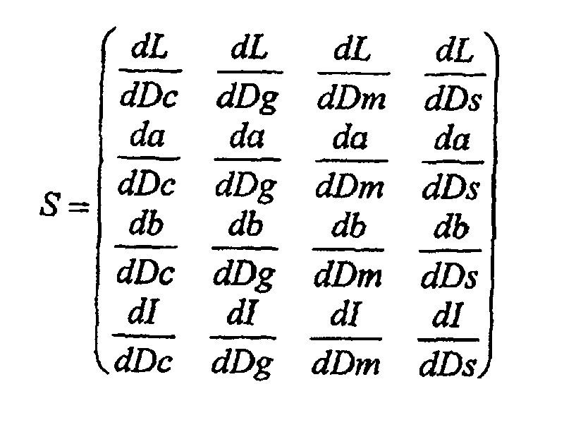
Die Koeffizienten der Sensitivitäts-Matrix S werden üblicherweise als
Farbwertgradienten bezeichnet. In den nachstehenden Ausführungen wird für diese 16
Farbwertgradienten stellvertretend jeweils der summarische Begriff Sensitivitäts-Matrix
verwendet.
Die Sensitivitätsmatrix S ist ein lineares Ersatzmodell für den Zusammenhang
zwischen den Änderungen der Schichtdicken der am Druck beteiligten Druckfarben
und den daraus resultierenden Änderungen des Farbeindrucks des mit den geänderten
Schichtdickenwerten gedruckten Bildelements 4. Die Sensitivitätsmatrix S ist nicht
für alle Farborte im Farbraum gleich, sondern gilt streng genommen jeweils nur in der
unmittelbaren Umgebung eines Farborts, d.h. für jeden gemessenen Farbvektor F der
einzelnen Bildelemente 4 ist in die Gleichung ΔF = S*ΔD streng genommen eine
eigene Sensitivitätsmatrix S einzusetzen. The coefficients of the sensitivity matrix S are usually called
Color value gradients. In the following explanations, 16
Color value gradients each represent the summary term sensitivity matrix
used.
The sensitivity matrix S is a linear replacement model for the relationship
between the changes in the layer thickness of the printing inks involved in the printing
and the resulting changes in the color impression of the with the changed
Layer thickness values of printed
Es sei darauf hingewiesen, daß es möglich ist, die Sensitivitätsmatrix S nur aus den
Komponenten L, a, b eines dreidimensionalen Farbvektors F zu bilden. Auf die
Komponente I kann verzichtet werden, wenn der Bildaufbau bei mehreren
Bildelementen 4 in Bezug auf die Flachendeckung der beteiligten Druckfarben
voneinander unabhängig ist, was in den meisten Fällen gegeben ist.It should be noted that it is possible to select the sensitivity matrix S only from the
To form components L, a, b of a three-dimensional color vector F. On the
Component I can be omitted if there are
Unter der Voraussetzung, dass die Sensitivitäts-Matrizen S bekannt sind, lässt sich die Matrizen-Gleichung ΔF = S*ΔD gemäss den bekannten Regeln des Matrizen-Kalküls nach ΔD auflösen (ΔD = S-1*ΔF). Auf die Bestimmung der Sensitivitäts-Matrizen wird weiter unten noch eingegangen.Provided that the sensitivity matrices S are known, the matrix equation ΔF = S * ΔD can be solved according to the known rules of the matrix calculation according to ΔD (ΔD = S -1 * ΔF). The determination of the sensitivity matrices is discussed further below.
Nach den vorstehenden Ausführungen umfasst jede Druckzone eine grosse Zahl, typischerweise etwa 4000, einzelne Bildelemente. Erfahrungsgemäss wirken sich die beim Druck auftretenden Störeinflüsse in der Regel nicht in gleicher Weise auf die einzelnen Bildelemente aus bzw. sind nicht alle Bildelemente durch dieselben Störeinflüsse betroffen. Die anhand eines Bildelements berechnete Schichtdickenänderung kann daher beispielsweise zwar für das eine Bildelement durchaus zu einer völligen Kompensation der Farbabweichung führen, für die anderen Bildelemente (derselben Zone) aber entweder ungenügend sein oder eine Richtungsänderung oder eine Vergrösserung der Farbabweichung hervorrufen. Da sich für jedes Bildelement in extremis ein anderer Schichtdickenänderungsvektor ΔD ergeben könnte, kann die Matrizen-Gleichung ΔF = S*ΔD nicht für jedes Bildelement unabhängig aufgelöst werden. Die einzelnen Matrizen-Gleichungen für die einzelnen Bildelemente müssen daher zu einem entsprechend der um 1 verminderten Anzahl der Bildelemente überbestimmtem Matrizen-Gleichungssystem zusammengefasst werden, das nach den bekannten Methoden der Ausgleichsrechnung unter Beiziehung einer Rahmen- oder Nebenbedingung zu lösen ist. Im Falle von 4000 Bildelementen ergibt sich also ein System von 4000 Matrizen-Gleichungen bzw. 16000 einfachen algebraischen Gleichungen mit den vier Unbekannten ΔDc, ΔDg, ΔDm und ΔDs. Als Nebenbedingung für die Lösung dieses Gleichungssystems wird praktischerweise gefordert, dass der mittlere quadratische Fehler minimal sein soll. Unter mittlerem quadratischen Fehler wird dabei der Mittelwert der Quadrate der nach der Anwendung der korrigierten Schichtdicken verbleibenden Farbabstände ΔE der einzelnen Bildelemente verstanden.According to the above explanations, each printing zone comprises a large number, typically approximately 4000, individual picture elements. Experience has shown that the interference that occurs during printing generally does not have the same effect on the individual image elements or that not all image elements are affected by the same interference. The change in layer thickness calculated on the basis of one picture element can therefore, for example, lead to a complete compensation of the color deviation for one picture element, but for the other picture elements (in the same zone) either be insufficient or cause a change in direction or an increase in the color deviation. Since a different layer thickness change vector ΔD could result for each picture element in extremis, the matrix equation ΔF = S * ΔD cannot be solved independently for each picture element. The individual matrix equations for the individual picture elements must therefore be combined to form a matrix equation system which is overdetermined according to the reduced number of picture elements and which is to be solved according to the known methods of compensation calculation using a framework or secondary condition. In the case of 4000 picture elements, there is a system of 4000 matrix equations or 16000 simple algebraic equations with the four unknowns ΔD c , ΔD g , ΔD m and ΔD s . As a secondary condition for the solution of this system of equations, it is practically required that the mean quadratic error should be minimal. The mean square error is understood to mean the mean value of the squares of the color distances ΔE of the individual picture elements remaining after the corrected layer thicknesses have been applied.
Die genannten 4000 Matrix-Gleichungen lassen sich übersichtlich wie folgt
zusammenfassen:
Darin bedeutet {ΔF} einen Spaltenvektor mit 16000 Komponenten (ΔL1, Δa1, Δb1,
ΔI1, ΔL2, Δa2, Δb2, ΔI2 ........ΔL4000, Δa4000, Δb4000, ΔI4000), {S} eine Matrix mit 4 Zeilen
und 4000 Spalten und ΔD einen Spaltenvektor mit den vier Unbekannten ΔDc, ΔDg,
ΔDm und ΔDs als Komponenten. Die Indizes der Komponenten von {ΔF} beziehen
sich auf die Bildelemente 4 1-4000, d.h. die Komponenten von {ΔF} sind die
ermittelten Komponenten der Farbabstandsvektoren ΔF der einzelnen Bildelemente 4
gegenüber den jeweils entsprechenden Bildelementen 4 des OK-Bogens. Die
rechteckige Matrix {S} ergibt sich durch eine Nebeneinanderreihung der 4000
Sensitivitäts-Matrizen S der einzelnen Bildelemente 4, also {S} = (S1 S2 .... S4000).Here {ΔF} means a column vector with 16000 components (ΔL 1 , Δa 1 , Δb 1 , ΔI 1 , ΔL 2 , Δa 2 , Δb 2 , ΔI 2 ........ ΔL 4000 , Δa 4000 , Δb 4000 , ΔI 4000 ), {S} a matrix with 4 rows and 4000 columns and ΔD a column vector with the four unknowns ΔD c , ΔD g , ΔD m and ΔD s as components. The indices of the components of {ΔF} relate to the
Nach den Regeln der Ausgleichsrechnung und mit der genannten Nebenbedingung
lässt sich die Lösung dieses Gleichungssystems allgemein wie folgt darstellen:
Darin ist {Q} eine rechteckige Matrix mit 4000 Spalten und 4 Zeilen, die sich
folgendermassen errechnet:
Wie man erkennt, ist die Berechnung des Schichtdickenänderungsvektors ΔD auf
diese Weise zwar prinzipiell möglich, erfordert aber einen enormen Rechenaufwand
und entsprechenden Zeitaufwand, der die Grenzen des praktisch Machbaren weit
übersteigt. Insbesondere ist auf diese Weise eine ausreichend schnelle Regelung, wie
sie in der Praxis insbesondere bei modernen Hochleistungsdruckmaschinen 1
erforderlich ist, nicht realisierbar. Der Rechenaufwand für die Bestimmung der 4000
Sensitivitätsmatrizen (insgesamt 64000 Koeffizienten) für die einzelnen
Bildelemente 4 ist dabei überhaupt noch nicht berücksichtigt und rückt die
Machbarkeit in noch weitere Ferne.As can be seen, the calculation of the layer thickness change vector ΔD is based on
Although this is possible in principle, it requires enormous computing effort
and corresponding expenditure of time that goes far beyond the limits of what is practically possible
exceeds. In particular, a sufficiently fast control, such as
in practice, especially in modern high-performance printing presses 1
is not feasible. The computing effort for determining the 4000
Sensitivity matrices (64,000 coefficients in total) for each
Hier setzt nun die Erfindung an. Der wesentlichste Grundgedanke der Erfindung
besteht darin, dass die einzelnen Bildelemente 4 nach bestimmten Kriterien zu
Gruppen oder Klassen zusammengefasst werden, innerhalb derer die
Farbabstandsvektoren und die Sensitivitäts-Matrizen summiert und gemittelt werden
und nur mit den Mittelwerten weitergerechnet wird. Auf diese Weise lässt sich das
Gleichungssystem für die Berechnung des Schichtdickenänderungsvektors erheblich
vereinfachen (typisch 81 anstatt 4000 Matrizen-Gleichungen pro Druckzone) und mit
vertretbarem Rechenaufwand für die Praxis ausreichend schnell (< 1 Minute für den
gesamten Druckbogen 3) lösen. Näheres dazu ist weiter unten ausgeführt.This is where the invention begins. The most important basic idea of the invention
is that the
Der visuelle Farbeindruck (messtechnisch der Farbwert, Farbort oder Farbvektor)
eines Bildelements 4 ist beim Offset-Raster-Druck durch die prozentualen
Rasterwerte (Flächendeckungen) der beteiligten Druckfarben und, in geringerem
Masse, durch die Schichtdicken der Druckfarben bestimmt. Die Rasterwerte bzw.
Flächendeckungen (0-100%) sind durch die zugrundeliegenden Druckplatten
festgelegt und praktisch unveränderlich. Einfluss auf den Farbeindruck genommen
und damit geregelt kann nur über die Schichtdicken der beteiligten Druckfarben
werden. Die Ausdrücke "Rasterwert" und "Flächendeckung" werden nachstehend
synonym verwendet. Die Gesamtheit aller möglichen Kombinationen R von
prozentualen Rasterwerten der beteiligten Druckfarben (üblicherweise Cyan, Gelb,
Magenta, Schwarz) sei im folgenden als Rasterraum (vierdimensional) bezeichnet.The visual color impression (metrologically the color value, color location or color vector)
of a
Unter gegebenen Druckbedingungen (Kennlinien der Druckmaschine 1, nominelle
Schichtdicken, zu bedruckender Stoff, verwendete Druckfarben etc.) entspricht jede
Rasterwertkombination R einem genau definierten Farbeindruck oder Farbvektor F
des mit dieser Rasterwertkombination R gedruckten Bildelements 4; es besteht also
eine eindeutige Zuordnung von Rasterwertkombination R zu Farbort bzw. Farbvektor
F; der Rasterraum lässt sich eindeutig auf den Farbraum abbilden, wobei allerdings
der Farbraum nicht vollständig belegt wird, da dieser auch nicht druckbare Farborte
enthält. Umgekehrt besteht im allgemeinen keine eindeutige Beziehung. Der zu einer
beliebigen Rasterwertkombination R gehörige Farbvektor F kann empirisch durch
Probedrucke ermittelt oder mittels eines geeigneten Modells, welches das
Druckverfahren unter den gegebenen Druckbedingungen ausreichend genau
beschreibt, errechnet werden. Ein geeignetes Modell ist z.B. durch die bekannten
Neugebauer-Gleichungen für den Offset-Druck gegeben. Das Modell setzt die
Kenntnis der Remissionsspektren von Einzelfarben-Volltönen, einigen
Übereinanderdrucken von Volltönen und einigen Rasterfeldern aller am Druck
beteiligten Druckfarben bei den nominellen Schichtdicken der Druckfarben voraus.
Diese Remissionsspektren lassen sich sehr einfach anhand eines Probedrucks messen.
Wenn die Kennlinien der Druckmaschine 1 bekannt sind, genügen einfache
Messungen an Volltönen.Under given printing conditions (characteristics of printing press 1, nominal
Layer thicknesses, material to be printed, printing inks used etc.) corresponds to each
Raster value combination R a precisely defined color impression or color vector F
the
Mit Hilfe des genannten Modells ist es in an sich bekannter Weise möglich, für jede beliebige Rasterwertkombination R die (16) Koeffizienten der zu dieser Rasterwertkombination gehörigen Sensitivitäts-Matrix S zu bestimmen. Dazu ist lediglich nötig, im Modell die nominellen Schichtdicken der beteiligten Druckfarben vorzugsweise einzeln jeweils um z.B. 1% zu ändern und mit diesen geänderten Schichtdicken die zugehörigen Farbvektoren und entsprechenden Farbabstandsvektoren gegenüber dem sich aus den nominellen Schichtdicken ergebenden Farbvektor zu berechnen. Diese Farbabstandsvektoren ΔF und die zugrundeliegenden Schichtdickenänderungsvektoren ΔD werden in die Gleichung ΔF = S*ΔD eingesetzt und diese nach den Koeffizienten der Sensitivitäts-Matrix S aufgelöst. With the help of the model mentioned, it is possible for everyone in a manner known per se any raster value combination R the (16) coefficients of this To determine the raster value combination belonging to the sensitivity matrix S. Is to only necessary in the model the nominal layer thicknesses of the printing inks involved preferably individually by e.g. 1% change and with these changed Layer thicknesses the corresponding color vectors and corresponding Color difference vectors compared to that resulting from the nominal layer thicknesses to calculate the resulting color vector. These color distance vectors ΔF and the underlying layer thickness change vectors ΔD are included in the equation ΔF = S * ΔD and this according to the coefficients of the sensitivity matrix S dissolved.
Bei der Bestimmung der Koeffizienten der Sensitivitäts-Matrix S können auch die
Flächendeckungswerte der Bildelemente 4 verwendet werden. Sind die
Flächendeckungswerte aus der Druckvorstufe bereits bekannt, so erübrigt sich eine
Messung an Probedrucken (Ausnahme: Volltöne).When determining the coefficients of the sensitivity matrix S, the
Area coverage values of the
Gemäss der Erfindung werden nun zu einer beschränkten Anzahl von möglichen Rasterwertkombinationen R der zugehörige Farbvektor F und die zugehörige Sensitivitäts-Matrix S im Voraus berechnet und in einer Tabelle abgespeichert. Diese die Gesamtheit aller so berechneten Sensitivitäts-Matrizen S und Farbvektoren F enthaltende Tabelle sei im folgenden als Raster-Farb-Tabelle RFT bezeichnet.According to the invention, there are now a limited number of possible Raster value combinations R the associated color vector F and the associated Sensitivity matrix S calculated in advance and stored in a table. This the entirety of all sensitivity matrices S and color vectors F calculated in this way containing table is referred to below as a raster color table RFT.
Für die Berechnung der Schichtdickenänderungsvektoren ΔD aus der Gleichung ΔF = S*ΔD ist, wie vorstehend ausgeführt, die Kenntnis der zum jeweiligen Farbort bzw. Farbvektor F gehörigen Sensitivitäts-Matrix S erforderlich. Um zu dieser zu gelangen, wird gemäss der Erfindung aus dem Farbvektor F des jeweiligen Bildelements nach einem besonders vorteilhaften Berechnungsverfahren, welches weiter unten noch näher erläutert ist, die zugehörige Rasterwertkombination R errechnet und anhand dieser Rasterwertkombination R die zugehörige Sensitivitäts-Matrix S aus der vorausberechneten Raster-Farb-Tabelle RFT entnommen. Auf diese Weise ist es möglich, ohne übermässigen Rechenaufwand schnell die benötigten Sensitivitäts-Matrizen zu bestimmen.For the calculation of the layer thickness change vectors ΔD from the equation As stated above, ΔF = S * ΔD is the knowledge of the respective color location or color vector F associated sensitivity matrix S required. To get to this arrive, according to the invention from the color vector F of the respective Picture element according to a particularly advantageous calculation method, which The associated raster value combination R is explained in more detail below calculates and on the basis of this raster value combination R the associated sensitivity matrix S taken from the pre-calculated raster color table RFT. To this In this way it is possible to quickly get the required without excessive computing effort Determine sensitivity matrices.
Gemäss einem weiteren Gedanken der Erfindung werden dazu im Rasterraum eine
Anzahl von z.B. 1296 gleichabständigen diskreten Rasterwertkombinationen RiR (je 6
diskrete Rasterprozentwerte AC, AG, AM, AS für die Druckfarben Cyan, Gelb,
Magenta, Schwarz) definiert:
Diese 1296 diskreten Rasterwertkombinationen RiR werden gemäss der nachstehenden
Formel mit einem eindeutigen Raster-Index iR numeriert:
Unter i(AC) .... ist dabei der Wert des Index i für den jeweiligen diskreten Rasterwert der jeweiligen Druckfarbe zu verstehen. Für jede dieser 1296 diskreten Rasterwertkombinationen RiR wird eine Sensitivitäts-Matrix SiR berechnet und in der Raster-Farb-Tabelle RFT abgelegt. Der zu den diskreten Rasterwertkombinationen RiR gehörende berechnete Farbvektor FiR wird ebenfalls in der Tabelle RFT abgelegt. Insgesamt enthält die Raster-Farb-Tabelle RFT damit 1296 Farbvektoren FiR und 1296 zugehörige Sensitivitäts-Matrizen SiR.I (A C ) .... is the value of the index i for the respective discrete screen value of the respective printing ink. A sensitivity matrix S iR is calculated for each of these 1296 discrete raster value combinations R iR and stored in the raster color table RFT. The calculated color vector F iR belonging to the discrete raster value combinations R iR is also stored in the table RFT. The raster color table RFT thus contains a total of 1296 color vectors F iR and 1296 associated sensitivity matrices S iR .
Die Quantisierung des Rasterraums erfolgt vorzugsweise in zwei Stufen. In der ersten Stufe werden für nur 256 diskrete Rasterwertkombinationen (entsprechend vier diskreten Rasterprozentwerten 0%, 40%, 80%, 100% für jede der Druckfarben Cyan, Gelb, Magenta, Schwarz) anhand des Offset-Druck-Modells die zugehörigen Farbvektoren und die zugehörigen Sensitivitäts-Matrizen berechnet. In der zweiten Stufe werden dann für die fehlenden Rasterprozentwerte 20% und 60% die zugehörigen Farbvektoren und Sensitivitäts-Matrizen durch lineare Interpolation aus den Farbvektoren und Sensitivitäts-Matrizen der jeweils 16 nächstliegenden diskreten Rasterwertkombinationen berechnet. Damit ergeben sich dann insgesamt wieder 1296 diskrete Rasterwertkombinationen RiR mit 1296 zugehörigen diskreten Farbvektoren FiR und 1296 zugehörigen Sensitivitäts-Matrizen SiR. Selbstverständlich könnte der Rasterraum auch auf eine andere Anzahl von diskreten Rasterkobinationen, beispielsweise etwa 625 oder 2401, reduziert werden, die Anzahl 1296 stellt aber für die Praxis einen optimalen Kompromiss zwischen Genauigkeit und Rechenaufwand dar.The grid space is preferably quantized in two stages. In the first stage, for only 256 discrete halftone value combinations (corresponding to four discrete halftone percentage values 0%, 40%, 80%, 100% for each of the printing colors cyan, yellow, magenta, black), the associated color vectors and the are based on the offset printing model associated sensitivity matrices. In the second stage, the associated color vectors and sensitivity matrices for the missing raster percentage values 20% and 60% are calculated by linear interpolation from the color vectors and sensitivity matrices of the 16 nearest discrete raster value combinations. This again results in a total of 1296 discrete raster value combinations R iR with 1296 associated discrete color vectors F iR and 1296 associated sensitivity matrices S iR . Of course, the grid space could also be reduced to a different number of discrete grid combinations, for example about 625 or 2401, but the number 1296 represents an optimal compromise between accuracy and computing effort in practice.
Einem für ein Bildelement 4 ermittelten Farbvektor F wird nun diejenige
Sensitivitäts-Matrix SiR zugeordnet, deren zugehörige diskrete Rasterwertkombination
RiR der aus dem Farbvektor F berechneten Rasterwertkombination R am nächsten
liegt. Anders ausgedrückt, wird die berechnete Rasterwertkombination R durch die
jeweils nächstliegende diskrete Rasterwertkombination RiR ersetzt und erhält die zu
dieser diskreten Rasterwertkombination RiR vorausberechnete Sensitivitäts-Matrix SiR
zugeordnet.A sensitivity matrix S iR whose associated discrete raster value combination R iR is closest to the raster value combination R calculated from the color vector F is now assigned to a color vector F determined for a
In einer anderen Betrachtungsweise wird der Rasterraum durch Aufteilung in eine
Anzahl von Unterräumen quantisiert. Alle Farbvektoren F, deren berechnete
zugehörigen Rasterwertkombinationen R in ein und denselben dieser Unterräume
fallen, erhalten dieselbe für diesen Unterraum vorausberechnete Sensitivitäts-Matrix
SiR zugeordnet. Die Unterräume sind durch die folgenden sechs Wertebereiche der
prozentualen Rasteranteile (Flächendeckungen) der vier beteiligten Druckfarben
definiert:
0....10, 10....30, 30....50, 50....70, 70....90, 90....100%In another view, the grid space is quantized by dividing it into a number of subspaces. All color vectors F, the calculated associated raster value combinations R of which fall into one and the same of these subspaces, are assigned the same sensitivity matrix S iR previously calculated for this subspace. The subspaces are defined by the following six value ranges of the percentage raster portions (area coverage) of the four printing inks involved:
0 .... 10, 10 .... 30, 30 .... 50, 50 .... 70, 70 .... 90, 90 .... 100%
Gemäss einem weiteren Aspekt der Erfindung wird für die Ermittlung der
Rasterwertkombination R aus dem Farbvektor F auch der (inkl. Infrarot-Wert I
vierdimensionale) Farbraum einer Quantisierung unterworfen, d.h. in eine Anzahl von
Unterräumen aufgeteilt. Dazu werden im Farbraum eine Anzahl von diskreten Farborten
mit jeweils diskreten Koordinatenwerten festgelegt. Die Quantisierung des
vierdimensionalen Farbraums kann beispielsweise so erfolgen, dass jede Dimension
L,a,b,I des Farbraums nur 11 diskrete Werte annehmen kann, wobei sich insgesamt
14641 diskrete Farborte FiF ergeben:
Diese 14641 diskreten Farborte FiF werden gemäss der nachstehenden Formel mit
einem eindeutigen Farbort-Index iF numeriert:
Für diese diskreten Farborte FiF des Farbraums werden nach der weiter unten noch erläuterten speziellen Berechnungsmethode die zugehörigen Rasterwertkombinationen RiF berechnet und, sofern sie nicht mit einer diskreten Rasterwertkombination RiR zusammenfallen, durch die jeweils nächstliegende diskrete Rasterwertkombination RiR ersetzt. Somit ergibt sich eine eindeutige, vorausberechnete Abbildung der 14641 diskreten Farborte FiF des (vierdimensionalen) Farbraums auf die 1296 diskreten Rasterwertkombinationen RiR des Rasterraums. Diese Abbildung wird, wie schon gesagt, vorausberechnet und in einer im folgenden als Raster-Index-Tabelle RIT bezeichneten Zuordnungstabelle abgespeichert.For these discrete color locations F iF of the color space, the associated raster value combinations R iF are calculated using the special calculation method explained below and, if they do not coincide with a discrete raster value combination R iR , are replaced by the closest discrete raster value combination R iR . This results in a clear, pre-calculated mapping of the 14641 discrete color locations F iF of the (four-dimensional) color space onto the 1296 discrete raster value combinations R iR of the raster space. As already mentioned, this mapping is calculated in advance and stored in an assignment table referred to below as the raster index table RIT.
Für die Zwecke der Ermittlung der Rasterwertkombinationen R aus den für die
Bildelemente 4 ermittelten Farbvektoren F wird jeder für ein Bildelement 4 ermittelte
Farbvektor F durch den nächstliegenden diskreten Farbort FiF ersetzt. Aus der Raster-Index-Tabelle
RIT wird dann die diesem diskreten Farbort FiF zugeordnete diskrete
Rasterwertkombination RiR entnommen und anhand dieser aus der Raster-Farb-Tabelle
RFT die entsprechende Sensitivitäts-Matrix SiR ausgelesen und dem
Farbvektor F zugeordnet. Auf diese Weise kann mit vergleichsweise geringem
Rechenaufwand und entsprechend schnell für jeden beliebigen ermittelten Farbvektor
F die Sensitivitäts-Matrix S bestimmt werden, wobei diese allerdings nur aus einer
der 1296 vorberechneten Sensitivitäts-Matrizen SiR ausgewählt werden kann. Für die
Praxis ist dies aber ausreichend.For the purposes of determining the raster value combinations R from the color vectors F determined for the
Für das Vorstehende wurde vorausgesetzt, dass aus den Farbvektoren F die
zugehörigen Rasterwertkombinationen R berechnet werden können. Wie dies gemäss
der Erfindung besonders vorteilhaft durchgeführt werden kann, ist Gegenstand der
nachstehenden Ausführungen.
Zunächst wird dazu der Farbraum in 81 Teilbereiche TiT wie folgt unterteilt:
First, the color space is divided into 81 sub-areas T iT as follows:
Die insgesamt 81 Teilbereiche TiT werden durch einen nach folgender Formel
definierten Teilbereichs-Index iT eindeutig durchnumeriert:
Innerhalb jedes Teilbereichs TiT wird nun der Zusammenhang zwischen dem
Farbvektor F und der zugehörigen, als Rastervektor A geschriebenen
Rasterwertkombination R durch die folgende Matrizen-Gleichung linear angenähert:
Darin bedeutet A den Rastervektor mit den Rasterprozentwerten AC, AG, AM, AS der vier beteiligten Druckfarben als Komponenten und UiT eine Umrechnungsmatrix mit 16 Koeffizienten, welche die partiellen Ableitungen (Gradienten) der Komponenten des Rastervektors nach den Komponenten des Farbvektors sind. Wenn die Umrechnungsmatrizen UiT der einzelnen Teilbereiche TiT bekannt sind, kann somit für jeden Farbvektor F der zugehörige Rastervektor A bzw. die zugehörige Rasterwertkombination R berechnet werden. A means the raster vector with the raster percentage values A C , A G , A M , A S of the four printing inks involved as components, and U iT a conversion matrix with 16 coefficients, which shows the partial derivatives (gradients) of the components of the raster vector according to the components of the color vector are. If the conversion matrices U iT of the individual partial areas T iT are known, the associated raster vector A or the associated raster value combination R can thus be calculated for each color vector F.
Das Problem reduziert sich also auf die Berechnung der Umrechnungsmatrizen UiT für die einzelnen Teilbereiche TiT bzw. genauer für die Farbvektoren FiT von deren Mittelpunkten. Die Berechnung der Umrechnungsmatrizen erfolgt durch eine gewichtete lineare Ausgleichsrechnung mit den Werten der weiter vorne erläuterten Raster-Farb-Tabelle RFT, also den 1296 diskreten Rasterwertkombinatione RiR und den zugehörigen diskreten Farbvektoren FiR. Für die Ausgleichsrechnung ist pro Teilbereich TiT im wesentlichen nur die Inversion einer 4x4-Matrix erforderlich. DasThe problem is therefore reduced to the calculation of the conversion matrices U iT for the individual sub-areas T iT or more precisely for the color vectors F iT from their centers. The conversion matrices are calculated using a weighted linear compensation calculation using the values from the raster-color table RFT explained above, that is to say the 1296 discrete raster value combinations R iR and the associated discrete color vectors F iR . For the compensation calculation, essentially only the inversion of a 4x4 matrix is required for each sub-area T iT . The
Gewicht der Stützstellen, d.h. die diskreten Farborte FiR der Raster-Farb-Tabelle RFT, für die Ausgleichsrechnung wird nach einer geeigneten Funktion mit dem Farbabstand zwischen den Stützstellen und dem jeweiligen Farbvektor FiT als Parameter bestimmt. Die Ausgleichsrechnung ist linear, d.h. an den Übergängen der einzelnen Teilbereiche TiT entstehen Unstetigkeiten, die aber für die Praxis unbedeutend sind.Weight of the support points, ie the discrete color locations F iR of the raster color table RFT, for the compensation calculation is determined according to a suitable function with the color distance between the support points and the respective color vector F iT as parameters. The compensation calculation is linear, ie there are discontinuities at the transitions of the individual sub-areas T iT , which are insignificant in practice.
Im folgenden wird das eigentliche Regelverfahren für die Farbgebung der Druckmaschine 1 näher beschrieben.In the following the actual control procedure for the coloring of the Printing machine 1 described in more detail.
Zu Beginn eines Auflagendrucks werden gemäss den vorstehenden Erläuterungen für
die herrschenden Druckbedingungen die Raster-Farb-Tabelle RFT und die Raster-Index-Tabelle
RIT berechnet und abgespeichert. Falls schon einmal bestimmt und auf
einem Speichermedium abgespeichert, können die Tabellen RFT, RIT natürlich auch
von diesem Speichermedium abgerufen werden. Anhand der beiden Tabellen RFT,
RIT ist es ohne substantiellen Rechenaufwand möglich, den für die einzelnen
Bildelemente 4 ermittelten Farbvektoren F die jeweils zutreffende diskrete
Sensitivitäts-Matrix S zuzuordnen.
Nun wird ein aktueller Druckbogen 3 dem laufenden Druckprozess entnommen und
mittels der Abtasteinrichtung 2 in der beschriebenen Art und Weise bildelementweise
ausgemessen, wobei im Rechner 5 für jedes Bildelement 4 der Farbvektor F und der
Farbabstandsvektor ΔF zum entsprechenden Bildelement 4 eines vorgängig analog
ausgemessenen OK-Bogens 23 bestimmt wird. Die Gesamtanzahl der Bildelemente 4
beträgt beispielsweise rund 130000, so dass bei den üblichen 32 Druckzonen die
Farbvektoren und Farbabstandsvektoren von jeweils rund 4000 Bildelementen 4 pro
Druckzone verarbeitet werden müssen. Die nachstehenden Ausführungen gelten
jeweils für eine Druckzone und für alle Druckzonen gleichermassen.At the start of a production run, the raster color table RFT and the raster index table RIT are calculated and saved in accordance with the above explanations for the prevailing printing conditions. If already determined and saved on a storage medium, the tables RFT, RIT can of course also be called up from this storage medium. On the basis of the two tables RFT, RIT, it is possible without substantial computing effort to assign the color vectors F determined for the
Now, a
Ein ganz wesentlicher Aspekt der vorliegenden Erfindung besteht, wie schon weiter
vorne erwähnt, in der Massnahme, dass die Bildelemente 4 nach bestimmten Kriterien
klassifiziert werden und die Messdaten der zu jeweils einer Klasse gehörenden
Bildelemente 4 gemittelt werden, wobei dann nur die Mittelwerte weiter verarbeitet
werden. Unter Messdaten werden hier die ermittelten Farbvektoren F und
Farbabstandsvektoren ΔF verstanden. Zur Klassifizierung der Bildelemente 4 werden
Sensitivitätsklassen gebildet. Für jede Sensitivitätsklasse sind die Sensitivitäten
(Sensitivitäts-Matrizen S) und auch die Farbvektoren F ähnlich, und daher ist eine
Mittelwertbildung zulässig. Der für die Regelung der Druckmaschine 1 erforderlicheA very important aspect of the present invention, as has been said before
mentioned above, in the measure that the
Schichtdickenänderungsvektor ΔD wird dann so berechnet, dass der mittlere
quadratische Fehler über alle Sensitivitätsklassen minimal sein soll. Unter mittlerem
quadratischen Fehler wird dabei der Mittelwert der Quadrate der nach der
Anwendung der korrigierten Schichtdicken verbleibenden mittleren Farbabstände der
Bildelemente 4 der einzelnen Klassen verstanden.Layer thickness change vector ΔD is then calculated so that the mean
quadratic error should be minimal across all sensitivity classes. Under middle
quadratic error is the mean of the squares according to the
Application of the corrected layer thicknesses remaining mean color distances of the
Die Bereiche der Sensitivitätsklassen werden vorzugsweise im Rasterraum definiert.
Beispielsweise können 16 - 256 Klassen vorgesehen sein. Je mehr Klassen vorliegen,
desto weniger entstehen Fehler durch die Mittelwertbildung, umso mehr steigt aber
der Rechenaufwand. Als praktikabler Kompromiss erweist sich die Definition von 81
Klassen, die sich aus einer Unterteilung des Rasterraums in 81 Unterräume nach dem
folgenden Schema ergeben:
Diese 81 Unterräume bzw. Sensitivitätsklassen KiK werden durch einen Klassen-Index
iK wie folgt eindeutig durchnumeriert:
Der Rasterraum umfasst, wie weiter vorne erläutert, 1296 diskrete Rasterwertkombinationen RiR. Somit fallen in jeden der 81 Unterräume genau 16 Rasterwertkombinationen RiR und dementsprechend in jede Sensitivitätsklasse KiK 16 (ähnliche) Sensitivitäts-Matrizen SiR.As explained further above, the grid space comprises 1296 discrete grid value combinations R iR . Exactly 16 raster value combinations R iR thus fall in each of the 81 subspaces and, accordingly, 16 (similar) sensitivity matrices S iR fall into each sensitivity class K iK .
Für jedes Bildelement 4 wird nun aus dem für dieses ermittelten Farbvektor F nach
der weiter vorne beschriebenen Vorgehensweise mittels der Raster-Index-Tabelle RIT
der zugehörige Raster-Index iR und daraus die Zugehörigkeit zu einer der 81For each
Sensitivitätsklassen KiK ermittelt. Anhand des Raster-Index iR und anhand der Raster-Farb-Tabelle
RFT wird weiter die zum Farbvektor F des Bildelements 4 zugehörige
Sensitivitäts-Matrix S bestimmt. Nach diesen Schritten liegen somit zu jedem der
rund 4000 Bildelemente 4 einer Druckzone der Farbvektor F, der Farbabstandsvektor
ΔF, der Raster-Index iR, die Sensitivitäts-Matrix S und der Klassen-Index iK vor. Der
Raster-Index iR definiert die Rasterwertkombination R, d.h. die prozentualen
Rasteranteile (Flächendeckungen) der beteiligten Druckfarben für das Bildelement 4,
der Klassen-Index iK definiert die Zugehörigkeit des Bildelements 4 zu einer
bestimmten Sensitivitäts-Klasse. Sensitivity classes K iK determined. Using the raster index iR and the raster color table RFT, the sensitivity matrix S associated with the color vector F of the
Als nächstes werden die Bildelemente 4 bzw. ihre Farbabstandsvektoren ΔF einem
Gewichtungsprozess unterzogen, welcher den Einfluss der Flächendeckung und von
Positionierungsfehlern berücksichtigt.Next, the
Für die nachfolgende Mittelwertbildung ist es vorteilhaft, wenn Bildelemente 4 mit
relativ kleinen Flächendeckungswerten weniger oder nicht berücksichtigt werden,
insbesondere sollten Bildelemente 4 mit Flächendeckungswerten unter 10%
unberücksichtigt bleiben. Demzufolge lässt sich ein erster,
flächendeckungsabhängiger Gewichtsfaktor g1 wie folgt definieren:
g1 = 1 für Flächendeckungen >= 10% und g1 = 0 für Flächendeckungen < 10%For the subsequent averaging, it is advantageous if
g1 = 1 for area coverage> = 10% and g1 = 0 for area coverage <10%
Da die Farbwerte L,a,b,I näherungsweise proportional zu den Flächendeckungen sind,
wird der erste Gewichtsfaktor vorzugsweise anhand des Farbabstands ΔE des
Bildelements zu einer unbedruckten Stelle des Druckbogens 3 (Papierweiss) wie folgt
definiert:
g1 = 1 für ΔEp 2 >= 52 und g1 = 0 für ΔEp 2 < 52 Since the color values L, a, b, I are approximately proportional to the area coverage, the first weighting factor is preferably defined as follows on the basis of the color distance ΔE of the picture element to an unprinted location on the printing sheet 3 (paper white):
g1 = 1 for ΔE p 2 > = 5 2 and g1 = 0 for ΔE p 2 <5 2
Darin ist ΔEp 2 das Quadrat des Farbabstands des Bildelements 4 zur unbedruckten
Stelle des Druckbogens 3 (Papierweiss).In it, ΔE p 2 is the square of the color distance of the
Eine andere Variante für die Bestimmung des Gewichtsfaktors g1 besteht darin, daß
dieser als Maximalwert den Wert 1 erhält, wenn die Summe der Flächendeckungen
des jeweiligen Bildelementes 4 einen vorgegebenen Schwellwert, vorzugsweise den
Wert 250 unterschreitet. Andernfalls erhält der Gewichtungsfaktor g1 einen kleineren,
insbesondere den Wert 0. Ebenfalls denkbar ist eine Kombination der beiden oben
genannten Varianten.Another variant for the determination of the weight factor g 1 is that it receives the value 1 as the maximum value if the sum of the area coverings of the
Dem Einfluss von Positionierungsfehlern wird durch einen zweiten Gewichtsfaktor
g2 Rechnung getragen. Es wird dabei davon ausgegangen, dass Bildelemente 4 in
einer homogenen Umgebung relativ unempfindlich auf Positionierungsfehler sind.
Unter homogener Umgebung wird verstanden, dass die Farbabstände des
Bildelements 4 zu seinen 8 benachbarten Bildelementen 4 relativ gering sind. In
diesem Fall wird der zweite Gewichtsfaktor auf g2 = 1 gesetzt. Mit zunehmenden
Farbabständen wird der zweite Gewichtsfaktor reduziert. Der zweite Gewichtsfaktor
g2 kann beispielsweise wie folgt bestimmt werden:
g2 = 1 für ΔEM <= 8 und g2 = (8/ΔEM) für ΔEM > 8The influence of positioning errors is taken into account by a second weighting factor g2. It is assumed that
g2 = 1 for ΔE M <= 8 and g2 = (8 / ΔE M ) for ΔE M > 8
Darin bedeutet ΔEM die Summe der Farbabstände des Bildelements 4 zu seinen 8
benachbarten Bildelementen 4. Eine bevorzugte, weil rechnerisch weniger
aufwendige, Definition des zweiten Gewichtsfaktors g2 ist durch die folgende
Beziehung gegeben:
g2 = 1 für ΔEM2 <= 8 und g2 = (8/ΔEM2)0.5 für ΔEM2 > 8In this, ΔE M means the sum of the color distances between the
g2 = 1 for ΔE M2 <= 8 and g2 = (8 / ΔE M2 ) 0.5 for ΔE M2 > 8
Darin bedeutet ΔEM2 die Summe der Quadrate der Farbabstände des Bildelements 4
zu seinen 8 benachbarten Bildelementen 4.In this, ΔE M2 means the sum of the squares of the color distances of the
Bei der Bestimmung des Gewichtsfaktors g2 kann auch die Differenz der
Flächendeckungswerte zu den benachbarten Bildelementen 4 herangezogen werden,
wobei bei zunehmender Differenz der Gewichtsfaktor g2 ebenfalls einen gegen 0
gehenden kleineren Wert erhält.
Die beiden Gewichtsfaktoren g1 und g2 werden zu einem für jedes Bildelement 4
individuellen kombinierten Gewichtsfaktor g gemäss g = g1*g2 kombiniert. Mit
diesen individuellen kombinierten Gewichtsfaktoren g werden nun die
Farbabstandsvektoren ΔF der einzelnen Bildelemente 4 und die zugehörigen
Sensitivitäts-Matrizen S multiplikativ gewichtet. Die gewichteten
Farbabstandsvektoren und Sensitivitäts-Matrizen der einzelnen Bildelemente 4 sind in
der Folge als ΔFg bzw. Sg bezeichnetWhen determining the weight factor g2, the difference between the area coverage values and the neighboring
The two weight factors g1 and g2 are combined to form an individual combined weight factor g for each
Anschliessend erfolgt für alle Bildelemente 4 jeweils einer Sensitivitätsklasse die
Mittelwertbildung und Normierung gemäss folgenden Formeln:
Die Summenbildung erfolgt dabei jeweils über alle Bildelemente einer Klasse. The totals are generated across all picture elements in a class.
Nach dieser Mittelwertbildung stehen pro Druckzone 81 mittlere Farbabstandsvektoren ΔFMK und 81 mittlere Sensitivitäts-Matrizen SMK zur Verfügung. Diese werden wie vorstehend beschrieben in die grundsätzliche Beziehung ΔF = S*ΔD eingesetzt und führen zu einem System von 81 Matrizen-Gleichungen, das nach dem unbekannten Schichtdickenänderungsvektor ΔD aufgelöst werden muss. Die Auflösung erfolgt wiederum mittels einer gewichteten linearen Ausgleichsrechnung mit der Nebenbedingung, dass der mittlere quadratische Fehler minimal sein soll, wobei unter dem mittleren quadratischen Fehler der Mittelwert der Quadrate der nach der Anwendung der durch ΔD korrigierten Schichtdicken verbleibenden mittleren Farbabstände ΔEMK der einzelnen Sensitivitätsklassen verstanden wird.After this averaging, 81 average color distance vectors ΔF MK and 81 average sensitivity matrices S MK are available per printing zone. As described above, these are inserted into the basic relationship ΔF = S * ΔD and lead to a system of 81 matrix equations, which must be solved for the unknown layer thickness change vector ΔD. The resolution is again carried out by means of a weighted linear compensation calculation with the additional condition that the mean square error should be minimal, whereby the mean square error means the mean value of the squares of the mean color distances ΔE MK of the individual sensitivity classes remaining after application of the layer thicknesses corrected by ΔD becomes.
Das Gleichungssystem stellt sich wie folgt dar:
Darin bedeutet {ΔFz} einen Spaltenvektor mit 4x81 Komponenten, der sich durch Untereinanderstellung der 81 Vektoren ΔFMK mit ihren je 4 Komponenten ergibt. {Sz} ist eine Matrix mit 4 Zeilen und 81 Spalten, die sich durch horizontale Nebeneinanderreihung der 81 Sensitivitäts-Matrizen SMK ergibt. ΔD ist ein Spaltenvektor mit den vier Unbekannten ΔDc, ΔDg, ΔDm und ΔDs als Komponenten.Here {ΔF z } means a column vector with 4x81 components, which results from the stacking of the 81 vectors ΔF MK with their 4 components each. {S z } is a matrix with 4 rows and 81 columns, which results from the 81 sensitivity matrices S MK being arranged horizontally side by side. ΔD is a column vector with the four unknowns ΔD c , ΔD g , ΔD m and ΔD s as components.
Nach den Regeln der Ausgleichsrechnung und mit der genannten Nebenbedingung
lässt sich die Lösung dieses Gleichungssystems allgemein wie folgt darstellen:
Darin ist {Qz} eine rechteckige Matrix mit 81 Spalten und 4 Zeilen, die sich
folgendermassen errechnet:
Als Ergebnis all dieser Berechnungen erhält man für jede Druckzone den gesuchten
Schichtdickenänderungsvektor ΔD mit seinen Komponenten ΔDc, ΔDg, ΔDm und ΔDs,
welche als Eingangsgrössen der Steuereinrichtung 9 zugeführt werden und die
erforderliche Verstellung der Farbgebungsorgane der Druckmaschine 1 in dem Sinne
hervorrufen, dass der genannte mittlere quadratische Fehler in jeder Druckzone
minimal wird.As a result of all these calculations, the desired layer thickness change vector ΔD with its components ΔD c , ΔD g , ΔD m and ΔD s are obtained for each printing zone, which are fed to the
Claims (14)
- Method for controlling the application of ink in a printing machine, in which a printed sheet (3) printed by the printing machine (1) is measured colorimetrically in a number of image elements (4) with respect to a selected colour coordinate system, the colour vectors (F) obtained in the process for each image element are used to calculate colour difference vectors (ΔF) in relation to desired colour vectors based on the same colour coordinate system and predefined or determined from a reference printed sheet, these colour difference vectors (ΔF) are converted with the aid of sensitivity matrices (S) into input variables, in particular layer thickness change vectors (ΔD), for a control device (9) for the inking elements of the printing machine (1), and the control of the inking of the printing machine (1) is performed on the basis of the input variables, in particular layer thickness change vectors (ΔD), converted from the colour difference vectors (ΔF), characterized in that, for each image element (4) measured on the printed sheet (3), its own sensitivity matrix (S) is determined, in that the image elements (4) are classified in accordance with sensitivity classes (KiK), in that the colour difference vectors (ΔF) and the sensitivity matrices (S) of the image elements (4) respectively belonging to a sensitivity class are averaged for each sensitivity class (KiK), and in that the aforementioned input variables, in particular layer thickness change vectors (ΔD), are calculated from the averaged colour difference vectors (ΔFMK) and the averaged sensitivity matrices (SMK) of all the sensitivity classes (KiK).
- Method according to Claim 1, characterized in that the sensitivity matrices (S) are determined from previously known area coverage values.
- Method according to Claim 1, characterized in that, for each image element (4), at least one measured value (I) is obtained in the near infrared region, in that the colour vector (F) determined for each image element (4) is four-dimensional, three components of the colour vector (F) being the coordinate values of an approximately equal-interval colour space and the fourth component being formed from the at least one measured value (I) in the near infrared region, in that the colour difference vector (ΔF) determined for each image element (4) is correspondingly four-dimensional, and in that the sensitivity matrix (S) determined for each image element (4) is formed by the gradients of the four components of the four-dimensional colour vector (F) in accordance with the printing inks involved in the print.
- Method according to Claim 1, characterized in that, for each image element (4), at least one measured value (I) is obtained in the near infrared region, in that the colour vector (F) determined for each image element (4) is four-dimensional, three components of the colour vector (F) being the coordinate values of an approximately equal-interval colour space and the fourth component being formed from the at least one measured value (I) in the near infrared region, in that the colour difference vector (ΔF) determined for each image element (4) is three-dimensional, and in that the sensitivity matrix (S) determined for each image element (4) is formed by the gradients of the three components of the three-dimensional colour vector (F) in accordance with the printing inks involved in the print.
- Method according to one of the preceding claims, characterized in that the colour difference vectors (ΔF) and the sensitivity matrices (S) of the image elements (4) respectively belonging to a sensitivity class (KiK) are averaged in a weighted fashion for each sensitivity class, each image element (4) being assigned weighting factors (g1; g2), which are determined from the area coverage of the image element (4) and/or the colour differences of the image element (4) in relation to its adjacent image elements (4).
- Method according to Claim 5, characterized in that the area coverages of each image element with respect to the printing inks involved are determined, in that one of the weighting factors (g1) of an image element (4) is given the value 1 if the average or one of the area coverages of the image element (4) is equal to a predefined first threshold value, in particular the value 10%, or exceeds this value, and in that the one of the weighting factors (g1) is otherwise given a smaller value, in particular the value 0.
- Method according to Claim 5, characterized in that the area coverages of each image element (4) with respect to the printing inks involved are determined, in that one of the weighting factors (g1) of an image element (4) is given a maximum value, in particular the value 1, if the sum of the area coverages of the respective image element (4) falls below a predefined threshold value, in particular the value 250, and in that the one of the weighting factors (g1) is otherwise given a smaller value, in particular the value 0.
- Method according to Claim 6 or 7, characterized in that, instead of the area coverages for each image element (4), the colour difference from an unprinted point on the printed sheet (3) is determined, in that the one of the weighting factors (g1) of an image element (4) is given the value 1 if the square of the colour difference of the image element is equal to a predefined second threshold value, in particular the value 52, or exceeds this value, and in that the one of the weighting factors (g1) is otherwise given a smaller value, in particular the value 0.
- Method according to Claim 5, characterized in that, for each image element (4), the colour differences from its immediately adjacent image elements (4) are determined, in that a further one of the weighting factors (g2) of an image element (4) is given the value 1 if the sum of the colour differences is equal to a predefined third threshold value, in particular the value 8, or falls below this value, and in that the further of the weighting factors (g2) is otherwise given a smaller value, which approaches 0 as the sum of the colour differences increases or as the difference of the area coverage in relation to the adjacent image elements (4) increases.
- Method according to Claim 9 and one of Claims 6 and 8, characterized in that, for each image element (4), a weighting factor (g) is determined, which results from a multiplicative combination of the further weighting factor (g2) calculated on the basis of the colour differences of the image element (4) from its adjacent image elements (4) and the one weighting factor (g1) calculated on the basis of the area coverages or the colour difference of the image element (4) in relation to an unprinted point on the printed sheet (3).
- Method according to one of the preceding claims, characterized in that, for a predefined first number of discrete raster value combinations (RiR) of the printing inks involved in the print, an associated sensitivity matrix (SiR) is calculated and stored in a raster colour table (RCT), in that for each image element (4) the associated raster value combination (R) is calculated from the colour vector (F) determined for this element, and in that the image element (4) is assigned that sensitivity matrix (SiR) from the raster colour table (RCT) whose associated discrete raster value combination (RiR) lies closest to the raster value combination (R) calculated for the image element (4).
- Method according to Claim 11, characterized in that, in the colour space expanded to four dimensions by the infrared component (I), a second number of discrete colour loci (FiF) is defined, in that for each of these discrete colour loci the associated raster value combination of the printing inks involved in the print is calculated, in that for each discrete colour locus the associated calculated raster value combination is replaced by the discrete raster value combination (RiR) located closest to it, and in that the associations between the discrete colour loci (FiF) and the discrete raster value combination (RiR) are stored in a raster index table (RIT).
- Method according to Claim 12, characterized in that, for the determination of the sensitivity matrix of an image element (4), the four-dimensional colour vector (F) determined for each element is replaced by the closest discrete colour locus (FiF), in that the raster value combination (RiR) associated with this discrete colour locus is taken from the raster index table (RIT), in that the sensitivity matrix (SiR) belonging to this raster value combination (RiR) is taken from the raster colour table (RCT), and in that this sensitivity matrix (SiR) is assigned to the image element (4).
- Method according to one of the preceding claims, characterized in that the sensitivity matrices (SiR) are calculated, with the aid of a mathematical model of the printing machine (1) used as a basis, from measured values on full-tone areas printed by the printing machine (1) and also taking into account the characteristic curves of the printing machine.
Applications Claiming Priority (2)
| Application Number | Priority Date | Filing Date | Title |
|---|---|---|---|
| DE19749066A DE19749066A1 (en) | 1997-11-06 | 1997-11-06 | Process for regulating the color application in a printing press |
| DE19749066 | 1997-11-06 |
Publications (3)
| Publication Number | Publication Date |
|---|---|
| EP0914945A2 EP0914945A2 (en) | 1999-05-12 |
| EP0914945A3 EP0914945A3 (en) | 1999-11-03 |
| EP0914945B1 true EP0914945B1 (en) | 2002-07-31 |
Family
ID=7847816
Family Applications (1)
| Application Number | Title | Priority Date | Filing Date |
|---|---|---|---|
| EP98119006A Expired - Lifetime EP0914945B1 (en) | 1997-11-06 | 1998-10-08 | Process for regulating the inking in a printing machine |
Country Status (4)
| Country | Link |
|---|---|
| US (1) | US5957049A (en) |
| EP (1) | EP0914945B1 (en) |
| JP (1) | JPH11216848A (en) |
| DE (2) | DE19749066A1 (en) |
Families Citing this family (23)
| Publication number | Priority date | Publication date | Assignee | Title |
|---|---|---|---|---|
| DE19749063A1 (en) * | 1997-11-06 | 1999-05-12 | Heidelberger Druckmasch Ag | Process for achieving color measurements for ink printers |
| US5967050A (en) * | 1998-10-02 | 1999-10-19 | Quad/Tech, Inc. | Markless color control in a printing press |
| DE10103555B4 (en) * | 2001-01-26 | 2019-12-19 | Volkswagen Ag | Procedure for assessing a layer of paint |
| CN1505564A (en) * | 2001-03-02 | 2004-06-16 | ������������˹��˾Dba Mgi���� | Printing adjustment system and method |
| MXPA04000988A (en) * | 2001-07-30 | 2005-02-17 | Ackley Martinez Company Dba Mg | Color management processing system and method. |
| MXPA04000987A (en) | 2001-07-30 | 2005-02-17 | Ackley Martinez Company Dba Mg | System admixture compensation system and method. |
| EP1433308A2 (en) * | 2001-10-04 | 2004-06-30 | E.I. Du Pont De Nemours And Company | Ink jet printing |
| US6938550B2 (en) * | 2002-10-31 | 2005-09-06 | R. R. Donnelley & Sons, Co. | System and method for print screen tonal control and compensation |
| US7437000B1 (en) * | 2003-03-14 | 2008-10-14 | Eric Rosenthal | Full spectrum color detecting pixel camera |
| DE50305862D1 (en) | 2003-10-23 | 2007-01-11 | Gretag Macbeth Ag | Color quality assessment and color control in color reproduction |
| DE102004061469A1 (en) * | 2004-12-18 | 2006-07-13 | Man Roland Druckmaschinen Ag | Method for controlling the color in an offset printing machine |
| US7605959B2 (en) | 2005-01-05 | 2009-10-20 | The Ackley Martinez Company | System and method of color image transformation |
| DE102005007780A1 (en) * | 2005-02-19 | 2006-08-31 | Man Roland Druckmaschinen Ag | Apparatus and method for measuring zonal coloring |
| JP2007030348A (en) * | 2005-07-27 | 2007-02-08 | Komori Corp | Method/device for adjusting ink supply to printing machine |
| US7252360B2 (en) * | 2005-10-25 | 2007-08-07 | Ecole polytechnique fédérale de Lausanne (EPFL) | Ink thickness variations for the control of color printers |
| US7652792B2 (en) | 2006-03-15 | 2010-01-26 | Quad/Tech, Inc. | Virtual ink desk and method of using same |
| DE102006025898A1 (en) | 2006-06-02 | 2007-12-06 | Heidelberger Druckmaschinen Ag | Method for calculating correction values in a color control or color control for a printing machine |
| DE102006048539A1 (en) * | 2006-10-13 | 2008-04-17 | Heidelberger Druckmaschinen Ag | Color measuring head positioning device |
| CN101186145B (en) * | 2006-11-20 | 2012-07-18 | 海德堡印刷机械股份公司 | Operating method of a device for the optical measurement of a printed sheet |
| DE102007029211A1 (en) * | 2007-06-25 | 2009-01-08 | Heidelberger Druckmaschinen Ag | Improved print control strip for color measurement on substrates |
| DE102009002822A1 (en) * | 2008-05-28 | 2009-12-03 | Manroland Ag | Operation of a cold foil unit with adhesive application |
| DE102010009226B4 (en) * | 2009-03-13 | 2024-02-15 | Heidelberger Druckmaschinen Ag | Method for controlling the ink application in a printing press |
| AT509239B1 (en) | 2009-12-17 | 2013-03-15 | Trumpf Maschinen Austria Gmbh | DRIVE DEVICE FOR A BEND PRESS |
Family Cites Families (15)
| Publication number | Priority date | Publication date | Assignee | Title |
|---|---|---|---|---|
| US4649502A (en) * | 1983-11-04 | 1987-03-10 | Gretag Aktiengesellschaft | Process and apparatus for evaluating printing quality and for regulating the ink feed controls in an offset printing machine |
| ATE47564T1 (en) * | 1985-12-10 | 1989-11-15 | Heidelberger Druckmasch Ag | PROCEDURE FOR INK ORDER CONTROL IN A PRINTING PRESS, APPROPRIATELY EQUIPPED PRINTING SYSTEM AND MEASURING DEVICE FOR SUCH PRINTING SYSTEM. |
| US4884221A (en) * | 1986-04-14 | 1989-11-28 | Minolta Camera Kabushiki Kaisha | Color measuring apparatus |
| DE3812099C2 (en) * | 1988-04-12 | 1995-01-26 | Heidelberger Druckmasch Ag | Process for color control of an offset printing press |
| DE4142481A1 (en) * | 1991-08-12 | 1993-02-18 | Koenig & Bauer Ag | QUALITY CONTROL OF AN IMAGE, FOR example A PRINTED PATTERN |
| DE59208384D1 (en) * | 1991-08-12 | 1997-05-28 | Koenig & Bauer Ag | Quality control of an image template e.g. B. a printed pattern |
| DE4308857A1 (en) * | 1993-03-19 | 1994-09-29 | Polygraph Contacta Gmbh | Method for controlling the application of ink in a printer |
| DE4335229C2 (en) * | 1993-10-15 | 1998-07-16 | Heidelberger Druckmasch Ag | Method for producing color samples produced on an offset printing press |
| EP0649743B1 (en) * | 1993-10-21 | 1997-04-09 | MAN Roland Druckmaschinen AG | Method for controlling the ink supply in a halftone printing machine |
| DE4431270C2 (en) * | 1993-10-21 | 1997-01-16 | Roland Man Druckmasch | Process for controlling the ink flow of an autotypically working printing machine |
| DE4343905C2 (en) * | 1993-12-22 | 1996-02-15 | Roland Man Druckmasch | Process for controlling the ink flow in a printing press |
| DE4415486C2 (en) * | 1994-05-03 | 1998-06-04 | Heidelberger Druckmasch Ag | Process for determining the permissible tolerances for the control or regulation of the coloring on a printing press |
| DE19515499C2 (en) * | 1995-04-27 | 1997-03-06 | Heidelberger Druckmasch Ag | Process for simultaneous multi-color control during printing |
| US5903712A (en) * | 1995-10-05 | 1999-05-11 | Goss Graphic Systems, Inc. | Ink separation device for printing press ink feed control |
| DE19650223A1 (en) * | 1996-12-04 | 1998-06-10 | Heidelberger Druckmasch Ag | Scanning device for pixel-by-pixel photoelectric measurement of a measurement object |
-
1997
- 1997-11-06 DE DE19749066A patent/DE19749066A1/en not_active Withdrawn
-
1998
- 1998-10-08 EP EP98119006A patent/EP0914945B1/en not_active Expired - Lifetime
- 1998-10-08 DE DE59804980T patent/DE59804980D1/en not_active Expired - Lifetime
- 1998-11-05 JP JP10314563A patent/JPH11216848A/en active Pending
- 1998-11-05 US US09/186,858 patent/US5957049A/en not_active Expired - Lifetime
Also Published As
| Publication number | Publication date |
|---|---|
| US5957049A (en) | 1999-09-28 |
| DE19749066A1 (en) | 1999-05-12 |
| DE59804980D1 (en) | 2002-09-05 |
| JPH11216848A (en) | 1999-08-10 |
| EP0914945A2 (en) | 1999-05-12 |
| EP0914945A3 (en) | 1999-11-03 |
Similar Documents
| Publication | Publication Date | Title |
|---|---|---|
| EP0914945B1 (en) | Process for regulating the inking in a printing machine | |
| EP0143744B1 (en) | Method and device for rating the printing quality and/or controlling the ink supply in an offset printing machine, and offset printing machine with such a device | |
| EP0324718B1 (en) | Method and device for ink monitoring in a printing machine | |
| EP0228347B2 (en) | Process for controlling the application of colours in a printing machine, printing device equipped therewith and measuring device for such a printing device | |
| EP0255924B1 (en) | Method and device for acting upon the inking of an inked surface in printing | |
| DE4431270C2 (en) | Process for controlling the ink flow of an autotypically working printing machine | |
| EP0142470A1 (en) | Method and device for judging the printing quality of a printed object, preferably printed by an offset printing machine, and offset printing machine provided with such a device | |
| EP0836941B1 (en) | Measuring field group and method for detecting quality data in multicolour printing editions | |
| EP0676285B1 (en) | Colour management in a sheet-fed rotary offset printing machine | |
| EP1525981A1 (en) | Color quality evaluation and inking regulating in color reproduction | |
| EP0659559A2 (en) | Method of controlling the ink supply in a printing machine | |
| EP0505323B1 (en) | Method of adjusting the screendot sizes of a rotary offset printing machine | |
| EP0916491B1 (en) | Method for the determination of colorimetric gradients | |
| EP0920994B1 (en) | Method of determination of colour values | |
| DE19830487B4 (en) | Method for determining area coverage in a printed image | |
| EP0668164B1 (en) | Quality data acquisition in a sheet-fed rotary offset printing machine | |
| DE19638967C2 (en) | Measuring field group and method for recording optical printing parameters in multi-color edition printing | |
| CH693533A5 (en) | Measuring field block and method for detecting Qualitotsdaten in multicolor print run. | |
| DE19738923A1 (en) | Measuring field block for detection of print quality | |
| DE19639014A1 (en) | Measurement field group for detecting quality data in multicolour overlay printing | |
| EP1033247B1 (en) | Method for controlling colour in a printing machine | |
| EP0649743A1 (en) | Method for controlling the ink supply in a halftone printing machine | |
| WO2023104966A1 (en) | Method for spectral colour density measurement in colour printing | |
| WO2024156674A1 (en) | Method for the inline monitoring of the mode of operation of at least one printhead |
Legal Events
| Date | Code | Title | Description |
|---|---|---|---|
| PUAI | Public reference made under article 153(3) epc to a published international application that has entered the european phase |
Free format text: ORIGINAL CODE: 0009012 |
|
| 17P | Request for examination filed |
Effective date: 19981008 |
|
| AK | Designated contracting states |
Kind code of ref document: A2 Designated state(s): BE CH DE FR GB IT LI NL |
|
| AX | Request for extension of the european patent |
Free format text: AL;LT;LV;MK;RO;SI |
|
| PUAL | Search report despatched |
Free format text: ORIGINAL CODE: 0009013 |
|
| AK | Designated contracting states |
Kind code of ref document: A3 Designated state(s): AT BE CH CY DE DK ES FI FR GB GR IE IT LI LU MC NL PT SE |
|
| AX | Request for extension of the european patent |
Free format text: AL;LT;LV;MK;RO;SI |
|
| AKX | Designation fees paid |
Free format text: BE CH DE FR GB IT LI NL |
|
| GRAG | Despatch of communication of intention to grant |
Free format text: ORIGINAL CODE: EPIDOS AGRA |
|
| GRAG | Despatch of communication of intention to grant |
Free format text: ORIGINAL CODE: EPIDOS AGRA |
|
| GRAH | Despatch of communication of intention to grant a patent |
Free format text: ORIGINAL CODE: EPIDOS IGRA |
|
| 17Q | First examination report despatched |
Effective date: 20020121 |
|
| GRAH | Despatch of communication of intention to grant a patent |
Free format text: ORIGINAL CODE: EPIDOS IGRA |
|
| GRAA | (expected) grant |
Free format text: ORIGINAL CODE: 0009210 |
|
| AK | Designated contracting states |
Kind code of ref document: B1 Designated state(s): BE CH DE FR GB IT LI NL |
|
| PG25 | Lapsed in a contracting state [announced via postgrant information from national office to epo] |
Ref country code: NL Free format text: LAPSE BECAUSE OF FAILURE TO SUBMIT A TRANSLATION OF THE DESCRIPTION OR TO PAY THE FEE WITHIN THE PRESCRIBED TIME-LIMIT Effective date: 20020731 Ref country code: IT Free format text: LAPSE BECAUSE OF FAILURE TO SUBMIT A TRANSLATION OF THE DESCRIPTION OR TO PAY THE FEE WITHIN THE PRESCRIBED TIME-LIMIT;WARNING: LAPSES OF ITALIAN PATENTS WITH EFFECTIVE DATE BEFORE 2007 MAY HAVE OCCURRED AT ANY TIME BEFORE 2007. THE CORRECT EFFECTIVE DATE MAY BE DIFFERENT FROM THE ONE RECORDED. Effective date: 20020731 |
|
| REG | Reference to a national code |
Ref country code: GB Ref legal event code: FG4D Free format text: NOT ENGLISH Ref country code: CH Ref legal event code: EP |
|
| REF | Corresponds to: |
Ref document number: 59804980 Country of ref document: DE Date of ref document: 20020905 |
|
| GBT | Gb: translation of ep patent filed (gb section 77(6)(a)/1977) |
Effective date: 20021008 |
|
| PG25 | Lapsed in a contracting state [announced via postgrant information from national office to epo] |
Ref country code: BE Free format text: LAPSE BECAUSE OF NON-PAYMENT OF DUE FEES Effective date: 20021031 |
|
| ET | Fr: translation filed | ||
| NLV1 | Nl: lapsed or annulled due to failure to fulfill the requirements of art. 29p and 29m of the patents act | ||
| BERE | Be: lapsed |
Owner name: *HEIDELBERGER DRUCKMASCHINEN A.G. Effective date: 20021031 |
|
| PLBE | No opposition filed within time limit |
Free format text: ORIGINAL CODE: 0009261 |
|
| STAA | Information on the status of an ep patent application or granted ep patent |
Free format text: STATUS: NO OPPOSITION FILED WITHIN TIME LIMIT |
|
| 26N | No opposition filed |
Effective date: 20030506 |
|
| PGFP | Annual fee paid to national office [announced via postgrant information from national office to epo] |
Ref country code: FR Payment date: 20101028 Year of fee payment: 13 |
|
| PGFP | Annual fee paid to national office [announced via postgrant information from national office to epo] |
Ref country code: GB Payment date: 20101025 Year of fee payment: 13 |
|
| GBPC | Gb: european patent ceased through non-payment of renewal fee |
Effective date: 20111008 |
|
| REG | Reference to a national code |
Ref country code: FR Ref legal event code: ST Effective date: 20120629 |
|
| PG25 | Lapsed in a contracting state [announced via postgrant information from national office to epo] |
Ref country code: GB Free format text: LAPSE BECAUSE OF NON-PAYMENT OF DUE FEES Effective date: 20111008 Ref country code: FR Free format text: LAPSE BECAUSE OF NON-PAYMENT OF DUE FEES Effective date: 20111102 |
|
| PGFP | Annual fee paid to national office [announced via postgrant information from national office to epo] |
Ref country code: DE Payment date: 20121211 Year of fee payment: 15 Ref country code: CH Payment date: 20121025 Year of fee payment: 15 |
|
| REG | Reference to a national code |
Ref country code: CH Ref legal event code: PL |
|
| PG25 | Lapsed in a contracting state [announced via postgrant information from national office to epo] |
Ref country code: LI Free format text: LAPSE BECAUSE OF NON-PAYMENT OF DUE FEES Effective date: 20131031 Ref country code: CH Free format text: LAPSE BECAUSE OF NON-PAYMENT OF DUE FEES Effective date: 20131031 |
|
| REG | Reference to a national code |
Ref country code: DE Ref legal event code: R119 Ref document number: 59804980 Country of ref document: DE Effective date: 20140501 |
|
| PG25 | Lapsed in a contracting state [announced via postgrant information from national office to epo] |
Ref country code: DE Free format text: LAPSE BECAUSE OF NON-PAYMENT OF DUE FEES Effective date: 20140501 |