EP0676285B1 - Colour management in a sheet-fed rotary offset printing machine - Google Patents
Colour management in a sheet-fed rotary offset printing machine Download PDFInfo
- Publication number
- EP0676285B1 EP0676285B1 EP95810055A EP95810055A EP0676285B1 EP 0676285 B1 EP0676285 B1 EP 0676285B1 EP 95810055 A EP95810055 A EP 95810055A EP 95810055 A EP95810055 A EP 95810055A EP 0676285 B1 EP0676285 B1 EP 0676285B1
- Authority
- EP
- European Patent Office
- Prior art keywords
- colour
- fields
- color
- variation
- tone
- Prior art date
- Legal status (The legal status is an assumption and is not a legal conclusion. Google has not performed a legal analysis and makes no representation as to the accuracy of the status listed.)
- Expired - Lifetime
Links
- 238000007645 offset printing Methods 0.000 title abstract description 10
- 238000000034 method Methods 0.000 claims abstract description 58
- 239000003086 colorant Substances 0.000 claims abstract description 39
- 238000007639 printing Methods 0.000 claims description 52
- 238000005259 measurement Methods 0.000 claims description 35
- 239000013598 vector Substances 0.000 claims description 35
- 230000009466 transformation Effects 0.000 claims description 26
- 230000008859 change Effects 0.000 claims description 14
- 238000000926 separation method Methods 0.000 claims description 14
- 238000004519 manufacturing process Methods 0.000 claims description 13
- 230000009897 systematic effect Effects 0.000 claims description 11
- 238000000326 densiometry Methods 0.000 claims description 8
- 230000000694 effects Effects 0.000 claims description 5
- 230000002301 combined effect Effects 0.000 claims description 4
- 230000008569 process Effects 0.000 abstract description 10
- 239000000976 ink Substances 0.000 description 46
- 239000000047 product Substances 0.000 description 32
- 239000007787 solid Substances 0.000 description 30
- 239000011159 matrix material Substances 0.000 description 7
- 230000008901 benefit Effects 0.000 description 6
- 238000012937 correction Methods 0.000 description 6
- 239000000463 material Substances 0.000 description 4
- 238000011156 evaluation Methods 0.000 description 3
- 230000003993 interaction Effects 0.000 description 3
- 230000003287 optical effect Effects 0.000 description 3
- 239000000523 sample Substances 0.000 description 3
- 238000004040 coloring Methods 0.000 description 2
- 238000000354 decomposition reaction Methods 0.000 description 2
- 238000001739 density measurement Methods 0.000 description 2
- 238000013461 design Methods 0.000 description 2
- 238000000844 transformation Methods 0.000 description 2
- 241001136792 Alle Species 0.000 description 1
- 241001295925 Gegenes Species 0.000 description 1
- 239000006227 byproduct Substances 0.000 description 1
- 230000007812 deficiency Effects 0.000 description 1
- 230000006872 improvement Effects 0.000 description 1
- 238000000691 measurement method Methods 0.000 description 1
- 238000012544 monitoring process Methods 0.000 description 1
- 238000005457 optimization Methods 0.000 description 1
- 238000004886 process control Methods 0.000 description 1
- 238000005070 sampling Methods 0.000 description 1
- 230000035945 sensitivity Effects 0.000 description 1
- 210000002023 somite Anatomy 0.000 description 1
- 238000010998 test method Methods 0.000 description 1
Images
Classifications
-
- B—PERFORMING OPERATIONS; TRANSPORTING
- B41—PRINTING; LINING MACHINES; TYPEWRITERS; STAMPS
- B41F—PRINTING MACHINES OR PRESSES
- B41F33/00—Indicating, counting, warning, control or safety devices
- B41F33/0036—Devices for scanning or checking the printed matter for quality control
- B41F33/0045—Devices for scanning or checking the printed matter for quality control for automatically regulating the ink supply
Definitions
- color management is that color templates in digital prepress are defined independently of output devices and materials. The colors are therefore described in a colorimetric coordinate system standardized by the Commission Internationale de l'Eclairage (CIE), such as XYZ, CIELAB or CIELUV. If multicolored images of this type are output on paper using a system calibrated in terms of color management, this ensures that the color appearance of the output is always the same, regardless of the output process used.
- CIE Commission Internationale de l'Eclairage
- EP 0 196 431 B1 describes a method and a device for achieving a uniform printing result on a multi-color offset printing machine that works in an autotypical manner.
- This solution is characterized by the measurement of ink layer thicknesses (solid ink densities) and halftone dot sizes (area coverage) at measuring fields, which are also printed for each printing ink in each inking zone of the press.
- the ink guide actuators on the printing press are set automatically on the basis of these densitometric measured values.
- EP 0 196 431 B1 has a further disadvantageous property in that features which have no direct relation to the color appearance of the printed product are measured with the solid and screen density of the individual colors.
- This deficiency can be countered by the fact that so-called combination measuring fields, i.e. Measuring fields in which the primary colors involved in the printing are printed on one another in a raster tone, provided and measured colorimetrically.
- Colorimetric measurement values obtained in this way can refer to the XYZ color space, which is based on the sensitivity function of the average human eye, or to the color spaces CIELUV or CIELAB derived from the XYZ system, all of which have been standardized by the CIE (Commission Internationale de l'Eclairage) .
- the colorimetric measurement on combination measuring fields has the advantage that it enables a statement about the interaction of all colors involved in a multicolor printing.
- the colorimetric measurement values directly say something about how the combination measuring field or the printed product appears in color to the human viewer.
- Another advantage is that the combination measuring fields can be replaced by image locations with a suitable image structure, if necessary.
- the disadvantage of colorimetric measurement methods is that they do not provide direct information about the process control. A deviation in the color location, for example, does not allow any conclusions to be drawn about how the ink guide on the printing press has to be corrected in order to reduce the deviation.
- EP 0 321 402 A1 and EP 0 408 507 A1 describe linear transformations for converting variations in full tone or screen density into variations in the color location of combination measuring fields in the CIELUV or CIELAB color spaces.
- the object of the invention is to provide measuring fields for recording color data of a printed product which are suitable for color management in web offset production and whose use in color management in particular enables a method which satisfies individual, several and preferably all of the requirements set out above .
- the method and the measuring fields developed for this purpose, or the measuring field group or arrangement, should also be usable in newspaper offset print runs.
- measuring fields and / or image points serving as measuring fields are also printed and optically scanned after printing.
- the returned light is evaluated.
- the printed product to be checked and a number of calibration prints produced with specifically different ink layer thicknesses each have a first combination measuring field, in which the basic colors, usually the three colors cyan, magenta and yellow, are overprinted with the nominal area coverage (F c1 , F m1 , F g1 ) are.
- at least one other primary color is varied, for example the first primary color by the value ⁇ F c2 in the second, the second primary color by the value ⁇ F m3 in the third and the third primary color by the value ⁇ F g4 in the fourth field.
- the number of additional combination measuring fields and the number of colors per combination measuring field preferably corresponds to the number of basic colors.
- the calibration prints additionally have at least one individual color grid in the basic colors for each basic color, which in its respective color has an area coverage that corresponds to that of the same color in the first combination measuring field. They preferably additionally have at least one different individual color grid for each primary color. The area coverage of the other single-color grid corresponds to the varied area coverage of the corresponding additional combination measurement area.
- the individual color grid fields in the preferred embodiment thus have the areas of coverage F c1 , F c2 , F m1 , F m3 , F g1 and F g4 .
- the calibration prints additionally contain at least one each Single-color full-tone field per basic color; preferably exactly one per basic color.
- the calibration print or prints can be printed separately or also in the printed product.
- the measuring fields form a measuring field group, which is preferably arranged in the form of a measuring field block.
- the color locus vectors R 1 , R 2 , R 3 and R 4 can be determined in a selected colorimetric coordinate system on these calibration prints by measurement with a color measuring device on the combination measuring fields.
- the effective area coverage in the pressure F ec1 , F ec2 , F em1 , F em3 , F eg1 , F eg4 and likewise in the single color full tone fields by densitometric measurement with a filter characteristic corresponding to the individual field can also be determined by densitometric or other measurements Vc1 , D Vm1 , D Vg1 can be determined.
- the color locus vectors, the solid color densities and the effective area coverage of the calibration prints are used according to the invention to determine two transformation functions A and B, which are a variation ⁇ D V1 of the solid color in the individual color solid tone fields caused by a change in the color layer thicknesses or a variation ⁇ F e1 of the effective area coverage in the individual areas Convert single color grid fields with the nominal area coverage F c1 , F m1 and F g1 into variations of the color locus vector of the first combination measuring field with the nominal area coverage (F c1 , F m1 , F g1 ).
- the color locus vector in the selected coordinate system is repeatedly determined on the printed product to be checked by measurement with a color measuring device on the first combination measuring field, and for that one predefined target color locus vector-related deviation of the color locus vector ⁇ R 11 determined on the printed product, a combination of a variation ⁇ D V11 of the solid color in existing or imagined single color solid color fields caused by changing the ink layer thicknesses and a variation ⁇ F e11 of the effective area coverage in existing or imaginary single color grid area fields with the nominal nominal area independent of this calculated.
- the deviation ⁇ R 11 of the color locus vector corresponds exactly to the combined effect of the variations ⁇ D V11 and ⁇ F e11 via the transformation functions A and B.
- the invention is further characterized in that the deviation of the color locus vector ⁇ R 11 on the printed product is corrected in the sense that on the one hand the calculated variation ⁇ D V11 of the solid ink densities by adjusting the ink guide actuators on the printing press and on the other hand the calculated variation ⁇ F e11 of the effective area coverage a change in the area coverage when the color separations are made to disappear; further in that the
- ⁇ R 11 ⁇ A ⁇ ⁇ ⁇ D V11 ⁇ + B ⁇ ⁇ ⁇ F e11 ⁇ applies.
- ⁇ R 11 ⁇ A ⁇ ⁇ ⁇ D V11 ⁇ + B ⁇ ⁇ ⁇ F e11 ⁇ applies where A ⁇ D V11 corresponds to the random part of ⁇ R 11 and B ⁇ F e11 represents the systematic part of ⁇ R 11 , ie constant part of ⁇ R 11 over several successive print jobs.
- a variation ⁇ F e11 of the effective area coverage in existing or imagined individual color grid fields with the nominal area coverage degrees F c1 , F m1 , and F g1 is calculated, independent of changes in the ink layer thicknesses , wherein the variation ⁇ R 11 corresponds exactly to the effect of the variation ⁇ F e11 via the transformation function B alone and that the deviation of the color location vector ⁇ R 11 on the printed product is corrected in the sense that the calculated variation ⁇ F e11 of the effective area coverage is compensated for as a result of a change in the area coverage independent of variations in the ink layer thickness when producing the color separations.
- the invention can be used with advantage in web offset printing.
- a measuring field group for recording color data of a printed product in particular for color management in web offset production printing, has a plurality of measuring fields, which can be optically scanned on a printed product to be checked or on Calibration print are printed.
- this measurement field group includes a first combination measurement field in which the basic colors with their nominal area coverage are printed one on top of the other, additional combination measurement fields in which the basic colors are printed with different nominal area coverage, each basic color being varied at least once in every additional combination measurement field, Furthermore, additional single-color grids in the primary colors, the first single-color grids in their respective primary colors having an area coverage that corresponds to that of the same color in the first combination measurement area.
- second individual color grid fields are provided, which have an area coverage in their respective primary color that corresponds to the varied area coverage of the same color in the additional combination measurement areas and finally additionally at least one individual color solid field for each primary color.
- the printed product 30 to be checked and optimized in the edition contains at least the combination measuring field 1 of the measuring fields described, in which the basic colors cyan, magenta and yellow with the nominal area coverage (F c1 , F m1 , F g1 ) are overprinted .
- an image point with an identical image structure can also serve as a combination measuring field.
- the calibration print 20 is used in particular with regard to the color material, the color layer thickness and the dot gain, i.e. the enlargement of the area coverage from the film template or the printing plate to the print, printed under standardized conditions. These conditions were set for the print run, for example by UGRA in Switzerland or FOGRA in Germany. It does not matter for the principle of operation whether the method according to the invention is used in newspaper or commercial web offset. The only essential is the requirement that the calibration print 20 according to the same standard as the edition, i.e. the printed product to be checked and optimized is produced.
- Further calibration prints 21, 22 and 23 also contain a measuring field block.
- the measuring field blocks of the calibration prints 20 to 23 are identical.
- the calibration prints 21, 22 and 23 are produced in a way that deviates from the applicable printing standard in that the color layer thickness of exactly one of the basic colors cyan, magenta and yellow is varied for each calibration print compared to the calibration print 20.
- the color layer thickness differs from cyan, that of magenta on the calibration print and that of yellow on the calibration print 23. In principle, the deviations can go in the positive or negative direction.
- the calibration prints 20 to 23 must also have other areas printed with all primary colors, so that sufficient color acceptance is guaranteed at the location of the measuring field block in the paper running direction. The design of these areas is free. Analogous considerations apply with regard to the ink acceptance for the printed product 30.
- the influence of the ink layer thickness is expressed in the differences between colorimetric and densitometric measurement values between the different calibration prints.
- the influence of the variations in the degree of surface coverage, which are independent of changes in the ink layer thicknesses, however, is noticeable in the differences in the measured values between the different measuring fields on one and the same calibration print.
- the transformation functions A and B are non-linear. Since we usually deal with relatively small variations around a standardized operating point in printing practice, it is permissible to linearize the relationships. In the interest of clarity, the method according to the invention is explained below using a linearized model. This does the generalizing wording in the claims to linear and non-linear systems does not break.
- the matrix B is calculated on the basis of the matrices ⁇ R Fe and ⁇ F e .
- ⁇ R Fe and ⁇ F e are defined by measured values that originate from calibration pressure 20 alone. This means that the matrix B can be determined completely on the basis of a single calibration pressure. In an extension of the method, it would be possible to determine a separate matrix B for several calibration prints and then to average the B over all B's . This measure could reduce the influence of random measurement errors.
- the transformation functions obtained from the calibration prints can now be used to advantage if the quality of production prints is to be monitored and optimized.
- the prerequisite for this is that the combination measuring field 1 is also printed in the printed product with the same nominal area coverage for cyan, magenta and yellow.
- the color locus vector R 11 in the combination measuring field 1 is measured on samples of the printed product 30 taken by sampling by measurement with a color measuring device.
- the target color locus vector can either be a measurement value originating from a given template or come directly from the digital prepress.
- ⁇ R 11M If one follows ⁇ R 11 over a longer period of time, ie over several productions, and forms the mean value ⁇ R 11M , in most cases ⁇ R 11M will differ from zero.
- ⁇ R 11M In conventional processes for controlling the color in offset printing, ⁇ R 11M would now be compensated for in every edition by adjusting the ink guide actuators on the printing press. If we now adopt the basic idea of color management in offset printing, we do not compensate for the systematic color locus deviation ⁇ R 11M by setting the printing press but by producing the color separations in the prepress stage by specifically influencing the area coverage.
- the method according to the invention makes it possible to use an image location with a suitable image structure instead of the combination measuring field 1 on the printed product 30.
- the space occupied by the combination measuring field 1 on the printed product can thereby be saved.
- the measurement data is collected with.
- densitometric values are determined using a densitometer, a spectrophotometer, a video camera or any other suitable device.
- colorimetric measurements with spectrophotometers, three-range color measuring devices, video cameras or other suitable devices are possible without breaking the invention.
- tools are used to further process the measurement data.
- the method according to the invention can also be extended in the direction of four-color overprinting, in that a proportion of the printing ink black is also permitted in the combination measuring fields on the calibration prints 20 to 23 and the printed product 30.
- the only condition is that the nominal area coverage of black is the same in all four combination measuring fields.
Abstract
Description
Die Grundidee des Color-Managements besteht darin, dass Farbvorlagen in der digitalen Druckvorstufe unabhängig von Ausgabegeräten und Materialien festgelegt werden. Die Farben werden demnach in einem durch die Commission Internationale de l'Eclairage (CIE) genormten farbmetrischen Koordinatensystem, wie XYZ, CIELAB oder CIELUV, beschrieben. Erfolgt die Ausgabe derart definierter mehrfarbiger Bilder auf Papier über ein im Sinne des Color-Managements kalibriertes System, so ist gewährleistet, dass die farbliche Erscheinung des Outputs immer gleich ist, ganz unabhängig vom verwendeten Ausgabeprozess.The basic idea of color management is that color templates in digital prepress are defined independently of output devices and materials. The colors are therefore described in a colorimetric coordinate system standardized by the Commission Internationale de l'Eclairage (CIE), such as XYZ, CIELAB or CIELUV. If multicolored images of this type are output on paper using a system calibrated in terms of color management, this ensures that the color appearance of the output is always the same, regardless of the output process used.
Als kalibrierbare Ausgabesysteme sind heute u.a. Computer-Farbdrucker, Digitalfarbkopierer und Digitalproofgeräte im Einsatz. Es ist vorteilhaft, das Konzept des Color-Managements auch auf konventionelle Druckverfahren wie den Zeitunsgsoffset auszudehnen. Dabei wird die aus Druckformherstellung und Druckprozess bestehende Wirkungskette wie irgend ein anderes kalibrierbares Ausgabegerät behandelt. Bis es so weit ist, müssen allerdings noch die Voraussetzungen dafür geschaffen werden, dass
- die farbliche Erscheinung mehrfarbig gedruckter Bilder auch im Zeitungsoffset-Auflagendruck systematisch erfasst,
- zufällige Abweichungen unterdrückt oder ausgeregelt und
- systematische Abweichungen kompensiert werden können.
- the color appearance of multicolor printed images is also systematically recorded in newspaper offset production,
- random deviations suppressed or corrected and
- systematic deviations can be compensated.
Für die Überwachung und Steuerung der Farbgebung im mehrfarbigen Offsetdruck sind heute zahlreiche Lösungen bekannt.Numerous solutions are known today for monitoring and controlling the coloring in multicolor offset printing.
Die EP 0 196 431 B1 beispielsweise beschreibt ein Verfahren und eine Vorrichtung zur Erzielung eines gleichförmigen Druckresultats an einer autotypisch arbeitenden Mehrfarbenoffsetdruckmaschine. Kennzeichnend für diese Lösung ist das Messen von Farbschichtdicken (Volltondichten) und Rasterpunktgrössen (Flächendeckungsgraden) an Messfeldern, die für jede Druckfarbe in jeder Farbstellzone der Druckmaschine mitgedruckt werden. Aufgrund dieser densitometrischen Messwerte werden die Farbführungsstellglieder an der Druckmaschine automatisch eingestellt.EP 0 196 431 B1, for example, describes a method and a device for achieving a uniform printing result on a multi-color offset printing machine that works in an autotypical manner. This solution is characterized by the measurement of ink layer thicknesses (solid ink densities) and halftone dot sizes (area coverage) at measuring fields, which are also printed for each printing ink in each inking zone of the press. The ink guide actuators on the printing press are set automatically on the basis of these densitometric measured values.
Die Notwendigkeit, in jeder Farbstellzone mehrere Messfelder mitzudrucken, hat dazu geführt, dass das erwähnte Verfahren bisher ausschliesslich im Akzidenzoffsetdruck zum Einsatz kam. Im Akzidenzoffsetdruck können die Messfelder nämlich ausserhalb des Satzspiegels, d.h. auf einem Rand mitgedruckt werden, welcher zum Schluss weggeschnitten wird. Diese Voraussetzung ist im Zeitungsoffset nicht erfüllt. Hier wird kein Rand weggeschnitten, allfällig mitgedruckte Messfelder müssen innerhalb des Satzspiegels untergebracht werden und nehmen so Platz in Anspruch, der sonst durch Inserate oder redaktionelle Beiträge genutzt werden könnte. Die Zeitungsverleger akzeptieren deshalb die Messfelder nur ungern.The need to print several measuring fields in each inking zone has meant that the above-mentioned method has so far only been used in commercial offset printing. In commercial offset printing, the measuring fields can be printed outside the type area, ie on an edge, which is then cut away. This requirement is not met in newspaper offset. No margin is cut away here, any measuring fields that are also printed must be accommodated within the type area and thus take up space that could otherwise be used by advertisements or editorial contributions. Newspaper publishers are therefore reluctant to accept the measuring fields.
Ein weiteres Hindernis für den Einsatz des obigen Verfahrens im Zeitungsoffset ist im hohen gerätemässigen und personellen Aufwand zu sehen, der bei dem Ausmessen der Messfelder entsteht. Soll das Ausmessen im Rollenoffset online, d.h. automatisch an der laufenden Bahn geschehen, so ist für jede Bahnseite ein optischer Messkopf mit automatischer Positionierung notwendig. Würde das Ausmessen stattdessen mit handelsüblichen Handdensitometern oder Handspektralphotometern vorgenommen, so müsste in Anbetracht der grossen Anzahl von Messfeldern und dem Zeitbedarf der manuellen Messgerätepositionierung eigens zum Zweck der Qualitätsdatenerfassung zusätzliches Personal eingestellt werden. Eine systematisch durchgeführte Qualitätsdatenerfassung kann sich im Zeitungsoffset-Auflagendruck nicht durchsetzen, solange sie mit hohen Investitionskosten oder grossem zusätzlichem Personalbedarf verbunden ist.Another obstacle to the use of the above method in newspaper offset is the high level of equipment and manpower that arises when measuring the measuring fields. Should the web offset measurement be online, i.e. happen automatically on the running web, an optical measuring head with automatic positioning is necessary for each web side. If the measurement were instead carried out with commercially available hand-held densitometers or hand-held spectrophotometers, additional personnel would have to be employed in view of the large number of measuring fields and the time required for manual measuring device positioning, especially for the purpose of quality data acquisition. A systematically carried out quality data acquisition cannot prevail in newspaper offset print run, as long as it is associated with high investment costs or large additional personnel requirements.
Das in EP 0 196 431 B1 beschriebene Verfahren weist eine weitere nachteilige Eigenschaft auf, indem mit den Vollton- und Rastertondichten der Einzelfarben Merkmale gemessen werden, welche keinen direkten Bezug zur farblichen Erscheinung des Druckerzeugnisses aufweisen. Diesem Mangel kann dadurch begegnet werden, dass auch sogenannte Kombinationsmessfelder, d.h. Messfelder in denen die am Druck beteiligten Grundfarben in einem Rasterton übereinandergedruckt sind, vorgesehen und farbmetrisch ausgemessen werden.The method described in EP 0 196 431 B1 has a further disadvantageous property in that features which have no direct relation to the color appearance of the printed product are measured with the solid and screen density of the individual colors. This deficiency can be countered by the fact that so-called combination measuring fields, i.e. Measuring fields in which the primary colors involved in the printing are printed on one another in a raster tone, provided and measured colorimetrically.
Solcherart gewonnene farbmetrische Messwerte können sich auf den an der Empfindlichkeitsfunktion des durchschnittlichen menschlichen Auges orientierten XYZ-Farbraum oder auf die vom XYZ-System abgeleiteten empfindungsgemäss gleichabständigen Farbräume CIELUV oder CIELAB beziehen, welche alle durch die CIE (Commission Internationale de l'Eclairage) genormt wurden.Colorimetric measurement values obtained in this way can refer to the XYZ color space, which is based on the sensitivity function of the average human eye, or to the color spaces CIELUV or CIELAB derived from the XYZ system, all of which have been standardized by the CIE (Commission Internationale de l'Eclairage) .
Die farbmetrische Messung an Kombinationsmessfeldern hat den Vorteil, dass sie eine Aussage über das Zusammenwirken aller an einem Mehrfarbendruck beteiligten Farben ermöglicht. Die farbmetrischen Messwerte sagen unmittelbar etwas darüber aus, wie das Kombinationsmessfeld bzw. das Druckerzeugnis dem menschlichen Betrachter farblich erscheint. Ein weiterer Vorteil besteht darin, dass die Kombinationsmessfelder gegebenenfalls durch Bildstellen mit einem geeigneten Bildaufbau ersetzt werden können. Im Gegensatz zu densitometrischen Verfahren wirkt sich an den farbmetrischen Messmethoden nachteilig aus, dass sie keine direkte Information zur Prozessführung liefern. Eine Abweichung des Farborts lässt beispielsweise keinen Schluss darüber zu, wie die Farbführung an der Druckmaschine korrigiert werden muss, um die Abweichung zu reduzieren.The colorimetric measurement on combination measuring fields has the advantage that it enables a statement about the interaction of all colors involved in a multicolor printing. The colorimetric measurement values directly say something about how the combination measuring field or the printed product appears in color to the human viewer. Another advantage is that the combination measuring fields can be replaced by image locations with a suitable image structure, if necessary. In contrast to densitometric methods, the disadvantage of colorimetric measurement methods is that they do not provide direct information about the process control. A deviation in the color location, for example, does not allow any conclusions to be drawn about how the ink guide on the printing press has to be corrected in order to reduce the deviation.
Es sind Methoden entwickelt worden, mit deren Hilfe Abweichungen des Farborts in Variationen der Schichtdicken oder der Dichten der am Druck beteiligten Einzelfarben umgerechnet werden können. So beschreiben die EP 0 321 402 A1 und EP 0 408 507 A1 lineare Transformationen zur Umrechnung von Variationen der Vollton- oder Rastertondichten in Variationen des Farborts von Kombinationsmessfeldern in den Farbräumen CIELUV oder CIELAB.Methods have been developed by means of which deviations in the color location can be converted into variations in the layer thicknesses or the densities of the individual colors involved in the printing. For example, EP 0 321 402 A1 and EP 0 408 507 A1 describe linear transformations for converting variations in full tone or screen density into variations in the color location of combination measuring fields in the CIELUV or CIELAB color spaces.
Diese Transformationen machen es möglich, beispielsweise aus einer Abweichung des Farborts von einem Kombinationsmessfeld an einem Probebogen die Änderung der Volltondichten von Einzelfarbenmessfeldern zu berechnen, die notwendig ist, um die Abweichung des Farborts im Kombinationsmessfeld zu kompensieren. Die verfolgte Strategie besteht demnach darin, unerwünschte Abweichungen des Farborts von Kombinationsmessfeldern ausschliesslich durch geeignete Veränderungen der Farbschichtdicken der am Druckprozess beteiligten Farben zu korrigieren.These transformations make it possible, for example, to calculate, from a deviation of the color location from a combination measuring field on a sample sheet, the change in the solid density of individual color measuring fields, which is necessary to compensate for the deviation of the color location in the combination measuring field. The strategy pursued is therefore to correct undesirable deviations in the color location of combination measuring fields exclusively by suitable changes in the ink layer thicknesses of the colors involved in the printing process.
Die Beschränkung auf Veränderungen der Farbschichtdicken in EP 0 408 507 A1 erscheint etwas willkürlich. Grundsätzlich ist nämlich die Korrektur von Farbortsabweichungen auch über eine passende Veränderung der Flächendeckungsgrade der einzelnen Druckfarben zu erreichen. Dies kann beispielsweise in der digitalen Druckvorstufe geschehen, wenn die Farbauszüge berechnet werden. Diese Möglichkeit ist besonders interessant, wenn die für ein bestimmtes Kombinationsmessfeld beobachteten Farbortsabweichungen zu einem wesentlichen Teil systematischer, d.h. nicht ausschliesslich zufälliger Natur sind. Ein weiterer Vorteil besteht darin, dass eine Veränderung der Flächendeckungsgrade der Druckfarben beim Berechnen der Farbauszüge oft leichter zu beherrschen ist als eine Veränderung der an der Druckmaschine geführten Farbschichtdicken. Die Idee, individuelle Druckkennlinien einzelner Farbwerke bei der Berechnung der Farbauszüge zu berücksichtigen, ist bereits aus der DE 42 09 165 A1 bekannt. Allerdings wird dort kein Bezug zu farbmetrischen Messwerten an Kombinationsmessfeldern oder Bildstellen hergestellt.The limitation to changes in the color layer thicknesses in EP 0 408 507 A1 appears somewhat arbitrary. Basically, the correction of color location deviations can also be achieved by a suitable change in the area coverage of the individual printing inks. This can be done, for example, in digital prepress when the color separations are calculated. This possibility is particularly interesting if the color location deviations observed for a specific combination measuring field are to a large extent systematic, ie not exclusively random. Another advantage is that a change in the area coverage of the printing inks is often easier to master when calculating the color separations than a change in the ink layer thicknesses carried out on the printing press. The idea of taking individual printing characteristics of individual inking units into account when calculating the color separations is already known from DE 42 09 165 A1. However, there is no reference to colorimetric measurement values at combination measuring fields or image points.
Aus den bisherigen Ausführungen folgt der Schluss, dass die heute bekannten und vornehmlich für den Akzidenzoffset-Auflagendruck bestimmten Verfahren zur Qualitätsdatenerfassung und zur Prozessoptimierung nicht unverändert auf den Zeitungsoffset-Auflagendruck übertragen werden können. Dies erklärt, warum heute im Zeitungsoffset noch immer die Praxis üblich ist, die Farbgebung durch das zwar geschulte aber eben subjektive Auge des Druckers zu überwachen und zu steuern. Für einen Einsatz im Zeitungsoffset-Auflagendruck ist eine Verbesserung der vorstehend besprochenen objektiven Verfahren erstrebenswert, insbesondere in folgender Hinsicht:
- Die notwendige Anzahl der Messfelder sollte reduziert werden, damit die Messfelder im Satzspiegel der Zeitung weniger Platz beanspruchen.
- Der gerätemässige und personelle Aufwand zum Ausmessen der Messfelder soll verkleinert werden.
- Die Verfahren sollten in Zukunft auf einer statistischen Kontrolle aufbauen. Messfelder werden dann nur in wenigen repräsentativen Farbzonen mitgedruckt und die Ergebnisse auf den gesamten Druckprozess extrapoliert. Dies kommt beiden vorhin aufgeführten Forderungen entgegen.
- Das Messen an Bildstellen mit einem geeigneten Bildaufbau soll das Mitdrucken und Ausmessen von speziellen Messfeldern so weit wie möglich unnötig machen.
- Aus derselben Messung sollten sowohl farbmetrische als auch densitometrische Messwerte resultieren. Dadurch kann gleichzeitig eine Aussage über die farbliche Erscheinung des Druckerzeugnisses und über die Möglichkeiten zu ihrer Korrektur sowohl in der Druckvorstufe wie an der Druckmaschine abgeleitet werden.
- The necessary number of measuring fields should be reduced so that the measuring fields in the type area of the newspaper take up less space.
- The device-related and personnel expenditure for measuring the measuring fields should be reduced.
- In the future, the procedures should be based on statistical control. Measuring fields are then only printed in a few representative color zones and the results are extrapolated to the entire printing process. This complies with both of the above requirements.
- Measuring at image points with a suitable image structure should make the printing and measuring of special measuring fields as unnecessary as possible.
- Both colorimetric and densitometric measurements should result from the same measurement. As a result, a statement about the color appearance of the printed product and about the possibilities for its correction can be derived both in the prepress stage and on the printing press.
Aufgabe der Erfindung ist es, Messfelder zur Erfassung von Farbdaten eines Druckerzeugnisses zu schaffen, die zum Color-Management im Rollenoffset-Auflagendruck geeignet sind und deren Einsatz beim Color-Management insbesondere ein Verfahren ermöglicht, daß einzelnen, mehreren und bevorzugt allen vorstehend aufgestellten Forderungen genügt. Das Verfahren und die dazu entwickelten Messfelder bzw. die Messfeldgruppe oder -anordnung sollen auch im Zeitungsoffset-Auflagendruck einsetzbar sein.The object of the invention is to provide measuring fields for recording color data of a printed product which are suitable for color management in web offset production and whose use in color management in particular enables a method which satisfies individual, several and preferably all of the requirements set out above . The method and the measuring fields developed for this purpose, or the measuring field group or arrangement, should also be usable in newspaper offset print runs.
Diese Aufgabe wird durch eine Messfeldgruppe nach dem Anspruch 1 und ein Verfahren nach den Ansprüchen 2 oder 3 gelöst. Die Unteransprüche stellen zweckmässige, nicht platt selbstverständliche Ausgestaltungen dazu dar. Die Lösung ist zwar durch die speziellen Anforderungen des Zeitungsdrucks geprägt, dies schliesst jedoch eine nutzbringende Anwendung auf andern Gebieten, wie dem Rollenakzidenzoffset keineswegs aus.This object is achieved by a measuring field group according to
Das erfindungsgemässe Verfahren beruht auf folgenden Überlegungen:
- Die farbliche Erscheinung einer im mehrfarbigen Übereinanderdruck bedruckten Fläche ist bei gegebenem Papier und Farbmaterial durch das Zusammenwirken der Farbschichtdicke und des effektiven Flächendeckungsgrades aller übereinanderliegenden Druckfarben bestimmt.
- Durch farbmetrische Messung an einem Kombinationsmessfeld, d.h. an einem Messfeld, in welchem mehrere Faden in Raster- oder Volltönen übereinandergedruckt sind, wird die kombinierte Wirkung der beteiligten Druckfarben durch eine einzige optische Antastung erfasst.
- Der Beitrag der einzelnen Farbe kann am besten durch ihre Schichtdicke und die Rasterpunktgrösse charakterisiert werden. Das densitometrische Äquivalent dazu sind die Volltondichte und der effektive Flächendeckungsgrad im Druck. Diese zwei Kenngrössen werden in Herkömmlichen Prüfverfahren pro beteiligte Druckfarbe durch Dichtemessung je an einem einfarbigen Kontrollfeld im Voll-und Rasterton gemessen. Die Berechnung des Flächendeckungsgrades aus Voll-und Rastertondichte geschieht üblicherweise nach der allgemeinbekannten Formel von Murray-Davies.
- Basiert die Qualitätsdatenerfassung im Offset-Auflagendruck ausschliesslich auf densitometrischen Messungen, so müssen pro Druckfarbe also mindestens zwei einfarbige Messfelder mitgedruckt werden. Diese Messfelder sind einzeln einer Dichtemessung zu unterziehen. Will man zusätzlich auch noch über das Zusammenwirken der Farbschichten Auskunft bekommen, so sind zur Bestimmung der Farbannahme zusätzliche densitometrische Messungen an weiteren zwei- und dreifarbigen Kombinationsmessfeldern notwendig. Im dreifarbigen Übereinanderdruck ergibt dies beispielsweise mindestens zehn optische Antastungen.
- Eine Verkleinerung des Aufwandes ergibt sich, wenn anstelle der Volltondichte und des Flächendeckungsgrades einer Farbe ihre Rastertondichte betrachtet wird. Die Rastertondichte gibt die kombinierte Wirkung der beiden anderen Einflussgrössen wieder. Allerdings ist dann eine differenzierte Betrachtung nach den Ursachen von Variationen schwieriger.
- Zwischen den an einem Kombinationsmessfeld ermittelten farbmetrischen Werten auf der einen Seite sowie den densitometrischen Kennwerten Volltondichte und Flächendeckungsgrad der Einzelfarben auf der anderen Seite besteht ein gesetzmässiger Zusammenhang. Dieser Zusammenhang ist generell kompliziert. Er lässt sich jedoch vereinfachen, wenn nur Variationen der interessierenden Grössen um einen bestimmten Arbeitspunkt betrachtet werden, was in der Druckereipraxis in Anbetracht der einschlägigen Standardisierungsanstrengungen meistens genügt.
- The color appearance of a surface printed in multicolored overprint is determined for a given paper and color material by the interaction of the ink layer thickness and the effective area coverage of all superimposed printing inks.
- By colorimetric measurement on a combination measuring field, ie on a measuring field in which several threads are printed one above the other in halftone or full tones, the combined effect of the printing inks involved is recorded by a single optical probe.
- The contribution of the individual color can best be characterized by its layer thickness and the dot size. The densitometric equivalent to this is the solid color density and the effective area coverage in the print. These two parameters are measured in conventional test methods for each printing ink involved by density measurement on a single-color control field in full tone and screen tone. The calculation of the area coverage from full and grid density is usually done according to the well-known Murray-Davies formula.
- If the quality data acquisition in offset production is based exclusively on densitometric measurements, at least two monochrome measuring fields must be printed with each printing ink. These measuring fields are to be individually subjected to a density measurement. If you also want to get information about the interaction of the color layers, additional densitometric measurements on further two and three-color combination measuring fields are necessary to determine the color acceptance. In three-color overprinting, this results in at least ten optical probes, for example.
- The effort is reduced if instead of the solid color density and the area coverage of a color its grid density is considered. The grid density reflects the combined effect of the two other influencing variables. However, it is then more difficult to differentiate between the causes of variations.
- Between the colorimetric values determined on a combination measuring field Values on the one hand and the densitometric parameters of solid color density and area coverage of the individual colors on the other hand are legally related. This relationship is generally complicated. However, it can be simplified if only variations of the sizes of interest around a certain working point are considered, which is usually sufficient in printing practice in view of the relevant standardization efforts.
Das folgende Vorgehen wird vorgeschlagen:
- Der systematische Zusammenhang zwischen den Variationen von farbmetrischen Kennwerten an Kombinationsmessfeldern und Variationen von Volltondichte und Flächendeckungsgrad der Einzelfarben wird an Eichdrucken für gegebenes Papier, Farbmaterial, eine bestimmte Druckmaschine und einen Arbeitspunkt empirisch bestimmt. Der Arbeitspunkt charakterisiert sich zweckmässigerweise durch die nominellen Flächendeckungsgrade der Einzelfärben im Kombinationsmessfeld, d.h. die Flächendeckungsgrade, welche das Kombinationsmessfeld auf den Filmvorlagen oder den Druckplatten aufweist.
- Das Ergebnis der Auswertung der Eichdrucke bildet somit pro Arbeitspunkt eine Transformationsfunktion, welche Variationen der Volltondichte in den Einzelfarbenvolltonfeldern und Variationen der effektiven Flächendeckungsgrade in den Einzelfarbenrasterfeldern in Variationen des Farbortsvektors des Kombinationsmessfeldes umrechnet.
- Ein Nebenergebnis der Auswertung der Eichdrucke ist eine Zerlegung der Variationen des Farbortsvektors nach den sie erzeugenden Ursachen, d.h. nach den Variationen der Volltondichte in den Einzelfarbenvolltonfeldern und den Variationen der effektiven Flächendeckungsgrade in den Einzelfarbenrasterfeldern. Aus dieser Zerlegung kann weiter das statistische Verhältnis der ursachenbezogenen Beiträge der Variationen des Farbortsvektors abgeleitet werden.
- Auf dem hinsichtlich seiner farblichen Erscheinung zu kontrollierenden und zu optimierenden Druckerzeugnis wird sodann lediglich das Kombinationsmessfeld mitgedruckt und farbmetrisch ausgemessen. Aus diesem gemessenen Ist-Farbort wird durch Subtraktion eines vorgegebenen Soll-Farbortes die Farborts-Abweichung oder Farborts-Variation berechnet.
- Die Farborts-Variation am Druckerzeugnis wird nun einerseits durch eine Verstellung der Farbführungsstellglieder an der Druckmaschine und andererseits durch eine Veränderung der Flächendeckungsgrade beim Herstellen der Farbauszüge kompensiert. Die Verstellung der Farbführungsstellglieder eignet sich dabei vorzugsweise zur Kompensation der zufälligen Anteile der Farborts-Variation, während sich die Veränderung der Flächendeckungsgrade beim Herstellen der Farbauszüge ausschliesslich zur Kompensation der systematischen, d.h. über mehrere Druckaufträge unveränderlichen, Anteile der Farborts-Variation anbietet.
- The systematic relationship between the variations in colorimetric parameters on combination measuring fields and variations in solid color density and area coverage of the individual colors is empirically determined on calibration prints for given paper, ink material, a specific printing machine and a working point. The operating point is expediently characterized by the nominal areas of coverage of the individual colors in the combination measurement field, ie the areas of coverage which the combination measurement area has on the film templates or the printing plates.
- The result of the evaluation of the calibration prints therefore forms a transformation function for each working point, which converts variations of the solid color density in the single-color full-tone fields and variations of the effective area coverage in the single-color grid fields into variations of the color locus vector of the combination measuring field.
- A by-product of the evaluation of the calibration prints is a decomposition of the variations of the color locus vector according to the causes that generated it, ie according to the variations of the solid color density in the single color solid tone fields and the variations of the effective area coverage in the single color halftone fields. The statistical relationship of the cause-related contributions of the variations in the color locus vector can also be derived from this decomposition.
- On the printed product to be checked and optimized with regard to its color appearance, only the combination measuring field is then also printed and measured colorimetrically. From this measured actual color location, the color location deviation or color location variation is calculated by subtracting a predetermined target color location.
- The color location variation on the printed product is now compensated on the one hand by adjusting the ink guide actuators on the printing press and on the other hand by changing the area coverage when producing the color separations. The adjustment of the ink guide actuators is preferably suitable for compensating for the random proportions of the color location variation, while the change in the area coverage when producing the color separations is only suitable for compensating for the systematic portions of the color location variation, ie unchangeable over several print jobs.
Zum Color-Management werden Messfelder und/oder als Messfelder dienende Bildstellen mitgedruckt und nach dem Drucken optisch abgetastet. Das remittierte Licht wird ausgewertet.For color management, measuring fields and / or image points serving as measuring fields are also printed and optically scanned after printing. The returned light is evaluated.
Erfindungsgemäß weisen das zu kontrollierende Druckerzeugnis und mehrere mit gezielt unterschiedlichen Farbschichtdicken hergestellte Eichdrucke je ein erstes Kombinationsmessfeld auf, in welchem die Grundfarben, üblicherweise die drei Farben Cyan, Magenta und Gelb, mit den nominellen Flächendeckungsgraden (Fc1, Fm1, Fg1) übereinandergedruckt sind.According to the invention, the printed product to be checked and a number of calibration prints produced with specifically different ink layer thicknesses each have a first combination measuring field, in which the basic colors, usually the three colors cyan, magenta and yellow, are overprinted with the nominal area coverage (F c1 , F m1 , F g1 ) are.
Die Eichdrucke weisen zusätzlich Kombinationsmessfelder auf, in welchen die Grundfarben mit den nominellen Flächendeckungsgraden (![]()
![]()
![]()
![]()
![]()
![]()
Die Eichdrucke weisen zusätzlich pro Grundfarbe zumindest je ein Einzelfarbenrasterfeld in den Grundfarben auf, das in seiner jeweiligen Farbe einen Flächendeckungsgrad besitzt, der dem der gleichen Farbe im ersten Kombinationsmessfeld entspricht. Bevorzugt weisen sie zusätzlich pro Grundfarbe zumindest noch je ein anderes Einzelfarbenrasterfeld auf. Der Flächendeckungsgrad des anderen Einzelfarbenrasterfeldes entspricht dem variierten Flächendeckungsgrad des entsprechenden zusätzlichen Kombinationsmessfeldes. In obiger Nomenklatur weisen die Einzelfarbenrasterfelder in der bevorzugten Ausführungsform somit die Flächendeckungsgrade Fc1, Fc2, Fm1, Fm3, Fg1 und Fg4 auf.The calibration prints additionally have at least one individual color grid in the basic colors for each basic color, which in its respective color has an area coverage that corresponds to that of the same color in the first combination measuring field. They preferably additionally have at least one different individual color grid for each primary color. The area coverage of the other single-color grid corresponds to the varied area coverage of the corresponding additional combination measurement area. In the above nomenclature, the individual color grid fields in the preferred embodiment thus have the areas of coverage F c1 , F c2 , F m1 , F m3 , F g1 and F g4 .
Weiterhin enthalten die Eichdrucke zusätzlich zumindest je ein Einzelfarbenvolltonfeld pro Grundfarbe; bevorzugterweise genau eines pro Grundfarbe.Furthermore, the calibration prints additionally contain at least one each Single-color full-tone field per basic color; preferably exactly one per basic color.
Der oder die Eichdrucke können gesondert oder auch in dem Druckerzeugnis mitgedruckt werden. Die Meßfelder bilden eine Meßfeldgruppe, die bevorzugterweise in Form eines Meßfeldblocks angeordnet ist.The calibration print or prints can be printed separately or also in the printed product. The measuring fields form a measuring field group, which is preferably arranged in the form of a measuring field block.
Vorteilhafterweise können an diesen Eichdrucken durch Messung mit einem Farbmeßgerät auf den Kombinationsmeßfeldern je die Farbortsvektoren R 1, R 2, R 3 und R 4 in einem gewählten farbmetrischen Koordinatensystem bestimmt werden. In den Einzelfarbenrasterfeldern können ferner durch densitometrische oder andere Messungen die effektiven Flächendeckungsgrade im Druck Fec1, Fec2, Fem1, Fem3, Feg1, Feg4 und ebenso in den Einzelfarbenvolltonfeldern durch densitometrische Messung mit einer dem einzelnen Feld entsprechenden Filtercharakteristik die Volltondichtewerte DVc1, DVm1, DVg1 bestimmt werden.Advantageously, the color locus vectors R 1 , R 2 , R 3 and R 4 can be determined in a selected colorimetric coordinate system on these calibration prints by measurement with a color measuring device on the combination measuring fields. In the individual color raster fields , the effective area coverage in the pressure F ec1 , F ec2 , F em1 , F em3 , F eg1 , F eg4 and likewise in the single color full tone fields by densitometric measurement with a filter characteristic corresponding to the individual field can also be determined by densitometric or other measurements Vc1 , D Vm1 , D Vg1 can be determined.
Die Farbortsvektoren, die Volltondichten und die effektiven Flächendeckungsgrade der Eichdrucke werden erfindungsgemäß zur Bestimmung zweier Transformationsfuntionen A und B verwendet, die eine durch Änderung der Farbschichtdicken bedingte Variation ΔD V1 der Volltondichte in den Einzelfarbenvolltonfeldern bzw. eine davon unabhängige Variation ΔF e1 der effektiven Flächendeckungsgrade in den Einzelfarbenrasterfeldern mit den nominellen Flächendeckungsgraden Fc1, Fm1 und Fg1 in Variationen des Farbortsvektors des ersten Kombinationsmessfeldes mit den nominellen Flächendeckungsgraden (Fc1, Fm1, Fg1) umrechnen.The color locus vectors, the solid color densities and the effective area coverage of the calibration prints are used according to the invention to determine two transformation functions A and B, which are a variation ΔD V1 of the solid color in the individual color solid tone fields caused by a change in the color layer thicknesses or a variation ΔF e1 of the effective area coverage in the individual areas Convert single color grid fields with the nominal area coverage F c1 , F m1 and F g1 into variations of the color locus vector of the first combination measuring field with the nominal area coverage (F c1 , F m1 , F g1 ).
Bei dem Verfahren nach der Erfindung wird an dem zu kontrollierenden Druckerzeugnis durch Messung mit einem Farbmessgerät auf dem ersten Kombinationsmessfeld wiederholt der Farbortsvektor in dem gewählten Koordinatensystem bestimmt und für die auf einen vorgegebenen Soll-Farbortsvektor bezogene Abweichung des am Druckerzeugnis ermittelten Farbortsvektors ΔR 11 eine Kombination einer durch Änderung der Farbschichtdicken bedingten Variation ΔD V11 der Volltondichte in vorhandenen oder gedachten Einzelfarbenvolltonfeldern und einer davon unabhängigen Variation ΔF e11 der effektivenen Flächendeckungsgrade in vorhandenen oder gedachten Einzelfarbenrasterfeldern mit den nominellen Flächendeckungsgraden berechnet.In the method according to the invention, the color locus vector in the selected coordinate system is repeatedly determined on the printed product to be checked by measurement with a color measuring device on the first combination measuring field, and for that one predefined target color locus vector-related deviation of the color locus vector ΔR 11 determined on the printed product, a combination of a variation ΔD V11 of the solid color in existing or imagined single color solid color fields caused by changing the ink layer thicknesses and a variation ΔF e11 of the effective area coverage in existing or imaginary single color grid area fields with the nominal nominal area independent of this calculated.
Die Abweichung ΔR 11 des Farbortsvektors entspricht erfindungsgemäß genau der kombinierten Wirkung der Variationen ΔD V11 und ΔF e11 über die Transformationsfunktionen A und B.According to the invention, the deviation ΔR 11 of the color locus vector corresponds exactly to the combined effect of the variations ΔD V11 and ΔF e11 via the transformation functions A and B.
Die Erfindung zeichnet sich ferner dadurch aus, daß die Abweichung des Farbortsvektors ΔR 11 am Druckerzeugnis in dem Sinne korrigiert wird, dass einerseits die berechnete Variation ΔD V11 der Volltondichten durch Verstellung der Farbführungsstellglieder an der Druckmaschine und andererseits die berechnete Variation ΔF e11 der effektiven Flächendeckungsgrade durch eine Veränderung der Flächendeckungsgrade beim Herstellen der Farbauszüge zum Verschwinden gebracht werden; ferner dadurch, daß dieThe invention is further characterized in that the deviation of the color locus vector ΔR 11 on the printed product is corrected in the sense that on the one hand the calculated variation ΔD V11 of the solid ink densities by adjusting the ink guide actuators on the printing press and on the other hand the calculated variation ΔF e11 of the effective area coverage a change in the area coverage when the color separations are made to disappear; further in that the
Transformationsfunktionen A und B linear, d.h. durch zwei 3x3-Matrizen A und B gekennzeichnet sind und dass die Beziehung ![]()
![]()
![]()
![]()
Weiterhin ist vorteilhaft, daß für eine Abweichung ΔR 11 des am Druckerzeugnis ermittelten Farbortsvektors eine Kombination einer durch Änderung der Farbschichtdicken bedingten Variation ΔD V11 der Volltondichten und einer davon unabhängigen Variation ΔF e11 der Flächendeckungsgrade derart berechnet wird, dass gleichzeitig ![]()
![]()
Weiterhin ist vorteilhaft, daß für eine Abweichung ΔR 11 des am Druckerzeugnis ermittelten Farbortsvektors eine durch Änderung der Farbschichtdicken bedingte Variation ΔD V11 der Volltondichten berechnet wird, wobei die Variation ΔR 11 genau der Wirkung der Variation ΔD V11 über die Transformationsfunktion A entspricht und dass die Abweichung des Farbortsvektors ΔR 11 am Druckerzeugnis in dem Sinne korrigiert wird, dass die berechnete Variation ΔD V11 der Volltondichten durch Verstellung der Farbführungsstellglieder an der Druckmaschine zum Verschwinden gebracht wird.It is also advantageous that for a deviation ΔR 11 of the color locus vector determined on the printed product, a variation ΔD V11 of the solid densities caused by a change in the ink layer thicknesses is calculated, the variation ΔR 11 corresponding exactly to the effect of the variation ΔD V11 via the transformation function A and that the deviation of the color locus vector ΔR 11 on the printed product is corrected in the sense that the calculated variation ΔD V11 of the solid densities is made to disappear by adjusting the ink guide actuators on the printing press.
Schließlich ist noch von Vorteil, daß für eine Abweichung ΔR 11 des am Druckerzeugnis ermittelten Farbortsvektors eine von Änderungen der Farbschichtdicken unabhängige Variation ΔF e11 der effektiven Flächendeckungsgrade in vorhandenen oder gedachten Einzelfarbenrasterfeldem mit den nominellen Flächendeckungsgraden Fc1, Fm1, und Fg1 berechnet wird, wobei die Variation ΔR 11 genau der Wirkung der Variation ΔF e11 über die Transformationsfunktion B allein entspricht und dass
die Abweichung des Farbortsvektors ΔR 11 am Druckerzeugnis in dem Sinne korrigiert wird, dass die berechnete Variation ΔF e11 der effektiven Flächendeckungsgrade infolge einer von Variationen der Farbschichtdicke unabhängigen Veränderung der Flächendeckungsgrade beim Herstellen der Farbauszüge kompensiert wird.Finally, it is also advantageous that for a deviation ΔR 11 of the color locus vector determined on the printed product, a variation ΔF e11 of the effective area coverage in existing or imagined individual color grid fields with the nominal area coverage degrees F c1 , F m1 , and F g1 is calculated, independent of changes in the ink layer thicknesses , wherein the variation ΔR 11 corresponds exactly to the effect of the variation ΔF e11 via the transformation function B alone and that
the deviation of the color location vector ΔR 11 on the printed product is corrected in the sense that the calculated variation ΔF e11 of the effective area coverage is compensated for as a result of a change in the area coverage independent of variations in the ink layer thickness when producing the color separations.
Die Erfindung kann mit Vorteil im Rollenoffset-Auflagedruck Verwendung finden.The invention can be used with advantage in web offset printing.
Eine Messfeldgruppe zur Erfassung von Farbdaten eines Druckerzeugnisses, insbesondere zum Color-Management im Rollenoffset-Auflagendruck weist mehrere Messfelder auf, die optisch abtastbar auf einem zu kontrollierenden Druckerzeugnis oder einem Eichdruck aufgedruckt sind.A measuring field group for recording color data of a printed product, in particular for color management in web offset production printing, has a plurality of measuring fields, which can be optically scanned on a printed product to be checked or on Calibration print are printed.
Erfindungsgemäss gehören zu dieser Messfeldgruppe ein erstes Kombinationsmessfeld, in welchem die Grundfarben mit ihren nominellen Flächendeckungsgraden übereinandergedruckt sind, zusätzliche Kombinationsmessfelder, in denen die Grundfarben mit variierten nominellen Flächendeckungsgraden übereinandergedruckt sind, wobei jede Grundfarbe zumindest einmal in jedem zusätzlichen Kombinationsmessfeld zumindest eine andere Grundfarbe variiert ist, ferner zusätzliche Einzelfarbenrasterfelder in den Grundfarben, wobei erste Einzelfarbenrasterfelder in ihrer jeweiligen Grundfarbe einen Flächendeckungsgrad besitzen, der dem der gleichen Farbe im ersten Kombinationsmessfeld entspricht. Vorzugsweise sind zweite Einzelfarbenrasterfelder vorgesehen, die in ihrer jeweiligen Grundfarbe einen Flächendeckungsgrad besitzen, der dem variierten Flächendeckungsgrad der gleichen Farbe in den zusätzlich Kombinationsmessfeldern entspricht und schliesslich zusätzlich mindestens ein Einzelfarbvolltonfeld für jede Grundfarbe.According to the invention, this measurement field group includes a first combination measurement field in which the basic colors with their nominal area coverage are printed one on top of the other, additional combination measurement fields in which the basic colors are printed with different nominal area coverage, each basic color being varied at least once in every additional combination measurement field, Furthermore, additional single-color grids in the primary colors, the first single-color grids in their respective primary colors having an area coverage that corresponds to that of the same color in the first combination measurement area. Preferably, second individual color grid fields are provided, which have an area coverage in their respective primary color that corresponds to the varied area coverage of the same color in the additional combination measurement areas and finally additionally at least one individual color solid field for each primary color.
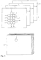
Die Funktionsweise des erfindungsgemässen Verfahrens wird nun anhand der Fig. 1 erklärt.The functioning of the method according to the invention will now be explained with reference to FIG. 1.
Ein Eichdruck 20 enthält einen aus 13 Messfeldern bestehenden Messfeldblock:
- In einem ersten dreifarbigen Kombinationsmessfeld 1 sind die Grundfarben Cyan, Magenta und Gelb mit den nominellen Flächendeckungsgraden (Fc1, Fm1, Fg1) übereinandergedruckt. In drei weiteren Kombinationsmessfeldern 2, 3 und 4 sind ebenfalls die Grundfarben Cyan, Magenta und Gelb übereinander gedruckt und zwar mit den nominellen Flächendeckungsgraden (


Bezogen auf Kombinationsmessfeld 1 ist also in jedem der Kombinationsmessfelder 2, 3 und 4 der nominelle Flächendeckungsgrad genau einer Grundfarbe variiert, d.h. in Kombinationsmessfeld 2 derjenige von Cyan um ΔFc2, in Kombinationsmessfeld 3 derjenige von Magenta um ΔFm3 und in Kombinationsmessfeld 4 derjenige von Gelb um ΔFg4. ΔFc2, ΔFm3 und ΔFg4 dürfen dabei sowohl positives wie negatives Vorzeichen aufweisen. - Drei weitere Einzelfarbenfelder 5, 6 und 7 enthalten die Volltöne von Cyan, Magente und Gelb.
- Sechs Einzelfarbenfelder sind mit Rastertönen bedruckt, und zwar Feld 8
und 11 in Cyan mit den nominellen Flächendeckungsgraden Fc1 und Fc2,Feld 9und 12 in Magenta mit den nominellen Flächendeckungsgraden Fm1 und Fm3 sowie Feld 10und 13 in Gelb mit den nominellen Flächendeckungsgraden Fg1 und Fg4.
- In a first three-color
combination measuring field 1, the basic colors cyan, magenta and yellow are printed with the nominal area coverage (F c1 , F m1 , F g1 ). In three further combination measuring fields 2, 3 and 4, the basic colors cyan, magenta and yellow are also printed on top of each other, with the nominal area coverage (combination measuring field 1, the nominal area coverage of exactly one basic color is varied in each of combination measuring fields 2, 3 and 4, i.e. in combination measuring field 2 that of cyan by ΔF c2 , in combination measuring field 3 that of magenta by ΔF m3 and in combination measuring field 4 that of yellow by ΔF g4 . ΔF c2 , ΔF m3 and ΔF g4 may have both positive and negative signs. - Three further single color fields 5, 6 and 7 contain the full tones of cyan, magente and yellow.
- Six single-color fields are printed with halftone tones, namely fields 8 and 11 in cyan with the nominal area coverage levels F c1 and F c2 , fields 9 and 12 in magenta with the nominal area coverage levels F m1 and F m3 as well as
field
Das in der Auflage zu kontrollierende und zu optimierende Druckerzeugnis 30 enthält von den beschriebenen Messfeldern mindestens das Kombinationsmessfeld 1, in welchem die Grundfarben Cyan, Magenta und Gelb mit den nominellen Flächendeckungsgraden (Fc1, Fm1, Fg1) übereinandergedruckt sind. Als Kombinationsmessfeld kann im, Prinzip auch eine Bildstelle mit identischem Bildaufbau dienen.The printed
Der Eichdruck 20 wird insbesondere in Bezug auf das Farbmaterial, die Farbschichtdicke und die Tonwertzunahme, d.h. die Vergrösserung des Flächendeckungsgrades von der Filmvorlage oder der Druckplatte zum Druck, unter standardisierten Bedingungen gedruckt. Diese Bedingungen wurden für den Auflagendruck beispielsweise durch die UGRA in der Schweiz oder die FOGRA in Deutschland festgelegt. Hierbei spielt es für die prinzipielle Funktionsweise keine Rolle, ob das erfindungsgemässe Verfahren im Zeitungs- oder aber im Akzidenzrollenoffset angewendet wird. Wesentlich ist einzig die Forderung, dass der Eichdruck 20 nach demselben Standard wie die Auflage, d.h. das zu kontrollierende und zu optimierende Druckerzeugnis, hergestellt wird.The
Weitere Eichdrucke 21, 22 und 23 enthalten ebenfalls einen Messfeldblock. In Bezug auf die Anordnung der Messfelder und deren Bildaufbau sind die Messfeldblöcke der Eichdrucke 20 bis 23 identisch. Die Eichdrucke 21, 22 und 23 werden insofern abweichend vom geltenden Druckstandard hergestellt, als pro Eichdruck verglichen mit dem Eichdruck 20 jeweils die Farbschichtdicke von genau einer der Grundfarben Cyan, Magenta und Gelb variiert wird. Auf dem Eichdruck 21 weicht die Farbschichtdicke von Cyan ab, auf dem Eichdruck 22 diejenige von Magenta und auf dem Eichdruck 23 diejenige von Gelb. Prinzipiell dürfen die Abweichungen in positive oder negative Richtung gehen.Further calibration prints 21, 22 and 23 also contain a measuring field block. With regard to the arrangement of the measuring fields and their image structure, the measuring field blocks of the calibration prints 20 to 23 are identical. The calibration prints 21, 22 and 23 are produced in a way that deviates from the applicable printing standard in that the color layer thickness of exactly one of the basic colors cyan, magenta and yellow is varied for each calibration print compared to the
Beim Herstellen der Eichdrucke 20 bis 23 ist eine weitere Bedingung einzuhalten. Nebst den Messfeldblöcken müssen die Eichdrucke nämlich noch weitere mit allen Grundfarben bedruckte Flächen aufweisen, damit am Ort des Messfeldblocks in Papierlaufrichtung eine genügende Farbabnahme garantiert ist. Die Gestaltung dieser Flächen ist frei. Analoge Überlegungen gelten in Bezug auf die Farbabnahme für das Druckerzeugnis 30.A further condition must be observed when producing the calibration prints 20 to 23. In addition to the measuring field blocks, the calibration prints must also have other areas printed with all primary colors, so that sufficient color acceptance is guaranteed at the location of the measuring field block in the paper running direction. The design of these areas is free. Analogous considerations apply with regard to the ink acceptance for the printed
Mithilfe der Eichdrucke 20 bis 23 können nun die zwei wichtigsten Einflüsse auf die farbliche Erscheinung des Kombinationsmessfeldes 1 quantitativ bestimmt werden. Es sind dies
- die mit Änderungen der Farbschichtdicken verbundenen Variationen der Volltondichte von Cyan, Magenta und Gelb sowie
- die von Änderungen der Farbschichtdicken unabhängigen Variationen der effektiven Flächendeckungsgrade von Cyan, Magenta und Gelb im Druck.
- the variations in solid ink density of cyan, magenta and yellow associated with changes in the color layer thicknesses as well
- the variations of the effective area coverage of cyan, magenta and yellow in the print independent of changes in the ink layer thickness.
Der Einfluss der Farbschichtdicken äussert sich hierbei in den Unterschieden von farbmetrischen und densitometrischen Messwerten zwischen den verschiedenen Eichdrucken. Der Einfluss der von Änderungen der Farbschichtdicken unabhängigen Variationen der Flächendeckungsgrade macht sich hingegen in den Unterschieden der Messwerte zwischen den verschiedenen Messfeldern auf ein und demselben Eichdruck bemerkbar.The influence of the ink layer thickness is expressed in the differences between colorimetric and densitometric measurement values between the different calibration prints. The influence of the variations in the degree of surface coverage, which are independent of changes in the ink layer thicknesses, however, is noticeable in the differences in the measured values between the different measuring fields on one and the same calibration print.
Bei der Bestimmung der Abhängigkeit der farblichen Erscheinung des Kombinationsmessfeldes 1 von den Volltondichten und den Flächendeckungsgraden der Grundfarben geht es darum, zwei Transformationsfunktionen zu bestimmen, und zwar:
- eine erste Transformationsfunktion A, welche eine durch Änderung der Farbschichtdicken bedingte Variation der Volltondichten in die dadurch resultierende Variation des Farbortes des Kombinationsmessfeldes umrechnet sowie
- eine zweite Transformationsfunktion B, welche eine von Änderungen der Farbschichtdicken unabhängige Variation der effektiven Flächendeckungsgrade in die dadurch resultierende Variation des Farbortes des Kombinationsmessfeldes abbildet.
- a first transformation function A, which converts a variation in the solid densities caused by changing the ink layer thicknesses into the resulting variation in the color location of the combination measuring field and
- a second transformation function B, which maps a variation of the effective area coverage independent of changes in the ink layer thicknesses into the resulting variation in the color location of the combination measuring field.
Im allgemeinen Fall sind die Transformationsfunktionen A und B nichtlinear. Da wir es in der Druckpraxis meist mit relativ kleinen Variationen um einen standardisierten Betriebspunkt zu tun haben, ist es zulässig, die Zusammenhänge zu linearisieren. Im Interesse der Übersichtlichkeit wird im folgenden das erfindungsgemässe Verfahren anhand eines linearisierten Modells erklärt. Dies tut der verallgemeinernden Formulierung in den Ansprüchen auf lineare und nichtlineare Systeme keinen Abbruch.In general, the transformation functions A and B are non-linear. Since we usually deal with relatively small variations around a standardized operating point in printing practice, it is permissible to linearize the relationships. In the interest of clarity, the method according to the invention is explained below using a linearized model. This does the generalizing wording in the claims to linear and non-linear systems does not break.
Zum Bestimmen der Transformationsfunktionen A und B bietet sich folgendes Vorgehen an:
- Es wird ein farbmetrisches Koordinatensystem, vorzugsweise XYZ, für die farbmetrischen Messungen festgelegt. Prinzipiell sind auch CIELAB oder CIELUV möglich. Wichtig ist, dass für die Angabe aller farbmetrischen Messwerte immer dasselbe System benutzt wird. Der Einfachheit halber basieren die weiteren Ausführungen beispielhaft auf Normfarbwerten XYZ.
- An
den Kombinationsmessfeldern 1 bis 4von Eichdruck 20 werden die Normfarbwerte XYZ gemessen. Es resultieren vier Farbortsvektoren
- An den Einzelfarbenfeldern 5
bis 13von Eichdruck 20 werden Farbdichten gemessen und mithilfe der allgemein bekannten Gleichung von Murray-Davies die effektiven Flächendeckungsgrade in den Messfeldern 8bis 13 berechnet. Es resultieren dabei drei Volltondichtewerte, und zwar DVc1 für Messfeld 5, DVm1 für Messfeld 6 und DVg1 für Messfeld 7. Weiter ergeben sich sechs Werte für den effektiven Flächendeckungsgrad im Druck, und zwar Fec1 für Messfeld 8, Fec2 für Messfeld 11, Fem1 für Messfeld 9, Fem2 für Messfeld 12, Feg1 für Messfeld 10 und Feg4 für Messfeld 13. Am Kombinationsmessfeld 1der Eichdrucke 21 bis 23 werden die Normfarbwerte XYZ gemessen. Es resultieren drei Farbortsvektoren
- Am Einzelfarbenfeld 5 des Eichdrucks 21 wird die Volltondichte für Cyan gemessen. Es resultiert der Wert DVc2.
- Am Einzelfarbenfeld 6 des Eichdrucks 22 wird die Volltondichte für Magenta gemessen. Es resultiert der Wert DVm3.
Am Einzelfarbenfeld 7 des Eichdrucks 23 wird die Volltondichte für Gelb gemessen. Es resultiert der Wert DVg4.- Mit den Definitionen


- Hier stehen die beiden 3x3-Matrizen A und B für die gesuchten Transformationsfunktionen A und B. Um zu den Transformationsfunktionen zu gelangen, müssen wir also die beiden letzten Gleichungen nur noch nach A und B auflösen:

- A colorimetric coordinate system, preferably XYZ, is defined for the colorimetric measurements. In principle, CIELAB or CIELUV are also possible. It is important that the same system is used for all colorimetric measurements. For the sake of simplicity, the further explanations are based, for example, on standard color values XYZ.
- The standard color values XYZ are measured on the
combination measuring fields 1 to 4 ofcalibration print 20. Four color locus vectors resultfield 1, R 2 for measuring field 2, R 3 for measuring field 3 and R 4 for measuring field 4. - Color densities are measured on the individual color fields 5 to 13 of
calibration print 20 and the effective area coverage in the measuring fields 8 to 13 is calculated using the generally known Murray-Davies equation. This results in three full-tone density values , namely D Vc1 for measuring field 5, D Vm1 for measuring field 6 and D Vg1 for measuringfield 7. There are also six values for the effective area coverage in the print, namely F ec1 for measuring field 8, F ec2 for measuringfield 11, F em1 for measuringfield 9, F em2 for measuringfield 12, F eg1 for measuringfield 10 and F eg4 for measuringfield 13. - The standard color values XYZ are measured on the
combination measuring field 1 of the calibration prints 21 to 23. The result is three color locus vectorscalibration pressure 21, R 22 for calibration pressure 22 and R 23 for calibration pressure 23. - The solid color density for cyan is measured on the individual color field 5 of the
calibration print 21. The result is D Vc2 . - The solid color density for magenta is measured on the individual color field 6 of the calibration print 22. The result is D Vm3 .
- The solid color density for yellow is measured on the
individual color field 7 of the calibration print 23. The result is D Vg4 . - With the definitions
- Here the two 3x3 matrices A and B stand for the transformation functions A and B we are looking for. To get to the transformation functions, we only have to solve the last two equations for A and B :
Durch Auswerten der Eichdrucke 20 bis 23 haben wir nun den quantitativen Zusammenhang zwischen Variationen der Volltondichte der Grundfarben, welche durch Änderungen der Farbschichtdicken bedingt sind und Variationen des Flächendeckungsgrades der Grundfarben, welche von Änderungen der Farbschichtdicken unabhängig sind auf der einen Seite und Variationen des Farbortsvektors im Kombinationsmessfeld 1 bestimmt.By evaluating the calibration prints 20 to 23, we now have the quantitative relationship between variations in the solid density of the primary colors, which are caused by changes in the ink layer thicknesses, and variations in the area coverage of the primary colors, which are independent of changes in the ink layer thicknesses, on the one hand, and variations in the color locus vector in the
Nach dem soeben beschriebenen Verfahren wird die Matrix B aufgrund der Matrizen ΔR Fe und ΔF e berechnet. ΔR Fe und ΔF e sind dabei durch Messwerte definiert, welche allein vom Eichdruck 20 stammen. Das bedeutet, dass die Matrix B vollständig aufgrund eines einzigen Eichdrucks bestimmt werden kann. In einer Erweiterung des Verfahrens wäre es möglich, für mehrere Eichdrucke je eine eigene Matrix B zu bestimmen und anschliessend über alle B den Mittelwert zu bilden. Durch diese Massnahme könnte der Einfluss von zufälligen Messfehlern reduziert werden.According to the method just described, the matrix B is calculated on the basis of the matrices ΔR Fe and ΔF e . ΔR Fe and ΔF e are defined by measured values that originate from
Die an den Eichdrucken gewonnenen Transformationsfunktionen können nun nutzbringend angewendet werden, wenn die Qualität von Auflagendrucken überwacht und optimiert werden soll. Voraussetzung dazu ist, dass im Druckerzeugnis das Kombinationsmessfeld 1 mit denselben nominellen Flächendeckungsgraden für Cyan, Magenta und Gelb mitgedruckt wird.The transformation functions obtained from the calibration prints can now be used to advantage if the quality of production prints is to be monitored and optimized. The prerequisite for this is that the
An stichprobenweise gezogenen Exemplaren des Druckerzeugnisses 30 wird durch Messung mit einem Farbmessgerät der Farbortsvektor R 11 im Kombinationsmessfeld 1 gemessen. Durch Bezug auf einen vorgegebenen Soll-Farbortsvektor R 0 errechnet sich anschliessend die Farbortsabweichung ![]()
![]()
Verfolgt man ΔR 11 nun über längere Zeit, d.h. über mehrere Produktionen und bildet den Mittelwert ΔR 11M , so wird ΔR 11M in den allermeisten Fällen von null verschieden sein. In herkömmlichen Verfahren zur Steuerung der Farbgebung im Offsetdruck würde ΔR 11M nun in jeder Auflage durch Verstellen der Farbführungsstellglieder an der Druckmaschine kompensiert. Übernehmen wir nun den Grundgedanken des Color-Managements in den Offsetdruck, so kompensieren wir die systematische Farbortsabweichung ΔR 11M nicht über die Einstellung der Druckmaschine sondern über die Herstellung der Farbauszüge in der Druckvorstufe, indem wir die Flächendeckungsgrade gezielt beeinflussen.If one follows ΔR 11 over a longer period of time, ie over several productions, and forms the mean value ΔR 11M , in most cases ΔR 11M will differ from zero. In conventional processes for controlling the color in offset printing, ΔR 11M would now be compensated for in every edition by adjusting the ink guide actuators on the printing press. If we now adopt the basic idea of color management in offset printing, we do not compensate for the systematic color locus deviation ΔR 11M by setting the printing press but by producing the color separations in the prepress stage by specifically influencing the area coverage.
Dazu eignet sich das folgende Verfahren:
- Man bestimmt mithilfe der Transformationsfunktion B eine von Änderungen der Farbschichtdicke unabhängige Variation


- Mithilfe der für den Druckprozess gültigen Druckkennlinien lassen such dann die Änderungen der nominellen Flächendeckungsgrade von Cyan, Magenta und Gelb im Farbauszug bestimmen, welche notwendig sind, um die systematische Farbortsabweichung ΔR 11M zu kompensieren.
- The transformation function B is used to determine a variation which is independent of changes in the ink layer thickness
- With the help of the printing characteristics that are valid for the printing process, we can then determine the changes in the nominal area coverage of cyan, magenta and yellow in the color separation, which are necessary to compensate for the systematic color location deviation ΔR 11M .
Wenn die systematische Farbortsabweichung kompensiert ist, bleiben immer noch zufällige Farbortsabweichungen ![]()
- Man bestimmt mithilfe der Transformationsfunktion A eine durch Änderungen der Farbschichtdicke bedingte Variation


- Durch Verstellung der Farbführungsstellglieder an der Druckmaschine werden die Farbschichtdicken so geregelt, dass ΔD v11 gegen null geht. Für das Ausregeln von ΔD v11 sind zwei Lösungen denkbar:
- Falls die Volltondichten von Cyan, Magenta und Gelb auf
dem Druckerzeugnis 30 direkt gemessen werden können, so brauchen nur die Volltondichte-Sollwerte um -ΔDvc11, -ΔDvm11 bzw. -ΔDvg11 verändert zu werden. Eine manuelle oder automatische Regelung auf die neuen Volltondichte-Sollwerte bringt dann ΔD v11 zum Verschwinden. - Falls
auf dem Druckerzeugnis 30 keine Volltondichten gemessen werden können, werden die Volltondichtevariationen ΔDvc11, ΔDvm11 bzw. ΔDvg11 mit den auf die Farbzone, welchedas Kombinationsmessfeld 1 enthält, bezogenen Flächendeckungssummen von Cyan, Magenta bzw. Gelb gewichtet. Dies ergibt ein direktes Mass für die Veränderung der in der Farbzone geführten Farbmengen der Grundfarben, welche zur Kompensation der Volltondichtevariation ΔD v11 führt. Die Veränderung der Farbmengen kann wiederum durch einen manuellen Eingriff oder durch automatische Steuerung erfolgen.
- Falls die Volltondichten von Cyan, Magenta und Gelb auf
- With the help of the transformation function A, a variation due to changes in the color layer thickness is determined
- By adjusting the ink guide actuators on the printing press, the ink layer thicknesses are controlled so that ΔD v11 goes to zero. Two solutions are conceivable for the correction of ΔD v11 :
- If the full tone densities of cyan, magenta and yellow can be measured directly on the printed
product 30, then only the full tone density setpoints need to be changed by -ΔD vc11 , -ΔD vm11 or -ΔD vg11 . Manual or automatic control to the new full-tone density setpoints then causes ΔD v11 to disappear. - If no full-tone densities can be measured on the printed product 30 , the full-tone density variations ΔD vc11 , ΔD vm11 or ΔD vg11 are weighted with the area coverage amounts of cyan, magenta or yellow related to the ink zone which contains the combination measuring field 1. This gives a direct measure of the change in the amount of color of the primary colors, which leads to the compensation of the solid density variation ΔD v11 . The change in the amount of color can again be done by manual intervention or by automatic control.
- If the full tone densities of cyan, magenta and yellow can be measured directly on the printed
Mit der soeben beschriebenen Anwendung des erfindungsgemässen Verfahrens wurde gezeigt, dass Variationen des Farbortsvektors R 11 im Kombinationsmessfeld 1 auf dem Druckerzeugnis 30 durch eine Kombination von Änderungen der Farbschichtdicken der Grundfarben Cyan, Magenta und Gelb sowie von Änderungen der nominellen Flächendeckungsgrade beim Herstellen der Farbauszüge in der Druckvorstufe kompensiert werden können.With the application of the method according to the invention that has just been described, it has been shown that variations in the color location vector R 11 in the
Bisher bekannte Verfahren zur Kompensation der Farbortsvariationen stützen sich demgegenüber allein auf die Beeinflussung der Farbführung an der Druckmaschine ab. Dies hat gegenüber dem erfindungsgemässen Verfahren einen entscheidenden Nachteil, der hier noch etwas ausgeleuchtet werden soll:
- Auf praxisüblichen mehrfarbigen Druckerzeugnissen gibt es in derselben Farbzone immer mehrere sich durch die nominellen Flächendeckungsgrade der Grundfarben unterscheidende Mischfarbtöne zu drucken. Diese Situation ist gleichwertig damit, dass
das Druckerzeugnis 30 in derselben Farbzone mehrere Messfelder mit unterschiedlichem Bildaufbau hat. - Für alle diese Messfelder wird nun gefordert, dass die Farbortsvariationen durch Verstellen der Farbführungsstellglieder an der Druckmaschine ausgeregelt werden. Im Normalfall wird jedes Messfeld eine andere Farbortsvariation aufweisen und deshalb eine andere Korrektur der Maschineneinstellung verlangen. Diese Bedingung kann nie erfüllt werden, so dass schlussendlich ein Kompromiss gefunden werden muss, durch den zwar die Farbortsvariationen in allen Kombinationsmessfeldern etwas reduziert aber niemals gleichzeitig zum verschwinden gebracht werden.
- In dieser Beziehung weist nun das erfindungsgemässe Verfahren einen bedeutenden Vorteil auf, indem es über die Veränderung der nominellen Flächendeckungsgrade beim Herstellen der Farbauzszüge individuelle Korrekturen für jedes Messefeld oder jede Bildstelle entsprechend dem Bildaufbau erlaubt. Auf diese Weise können die systematischen Anteile der Farbortsvariation vollständig kompensiert werden.
- There are always several mixed colors to be printed in the same color zone on standard multicolored printed products, which differ by the nominal area coverage of the primary colors. This situation is equivalent to the fact that the printed
product 30 has several measurement fields with different image structures in the same color zone. - For all of these measuring fields, it is now required that the color location variations are corrected by adjusting the ink guide actuators on the printing press. Normally, each measuring field will have a different color location variation and therefore require a different correction of the machine setting. This condition can never be met, so that ultimately a compromise has to be found by which the color location variations in all combination measuring fields are somewhat reduced, but never made to disappear at the same time.
- In this regard, the method according to the invention has an important advantage in that it allows individual corrections for each measuring field or each image location in accordance with the image structure by changing the nominal area coverage when producing the color separations. In this way, the systematic parts of the color location variation can be fully compensated.
Die Kompensation der systematischen Farbortsvariationen durch Änderungen der nominellen Flächendeckungsgrade beim Herstellen der Farbauszüge in der Druckvorstufe ist besonders interessant im Zusammenhang mit neueren farbzonelosen Druckmaschinenkonzepten. Diese Druckmaschinen verhalten sich in Bezug auf die Konstanz der Farbführung über mehrere Auflagen stabil, sind aber durch das Verstellen von Farbführungsstellgliedern kaum zu steuern. Hier ist die Korrektur von Farbortsabweichungen durch die Beeinflussung der nominellen Flächendeckungsgrade in der Druckvorstufe die Methode der Wahl.The compensation of the systematic color location variations by changing the nominal area coverage when producing the color separations in the prepress is particularly interesting in connection with newer color zone-less printing press concepts. These printing presses are stable with regard to the consistency of the ink guide over several runs, but can hardly be controlled by adjusting the ink guide actuators. Correction of color location deviations by influencing the nominal area coverage in prepress is the method of choice here.
Das erfindungsgemässe Verfahren erlaubt es, anstelle des Kombinationsmessfeldes 1 auf dem Druckerzeugnis 30 eine Bildstelle mit geeignetern Bildaufbau zu benutzen. Dadurch kann der durch das Kombinationsmessfeld 1 beanspruchte Raum auf dem Druckerzeugnis eingespart werden.The method according to the invention makes it possible to use an image location with a suitable image structure instead of the
Eine weitere sinnvolle Anwendung des erfindungsgemässen Verfahrens besteht darin, dass in dem Druckerzeugnis 30 der komplette Messfeldblock der Eichdrucke 20 bis 23 mitgedruckt wird, so dass auf die eigentlichen Eichdrucke verzichtet werden kann.
- Es ist problemlos möglich, zur Bestimmung der Transformationsfunktion B beispielsweise das erste gute Exemplar der Auflage anstelle des Eichdrucks 20 zu verwenden.
- Die Transformationsfunktion A lässt sich dann ebenfalls aufgrund von weiteren drei Exemplaren, die der Auflage entnommen werden, ermitteln, sofern über die Auflage genügend grosse Schwankungen der Volltondichte der Grundfarben vorkommen. Die Auswertung erfolgt durch eine Verallgemeinerung des oben angegebenen Rechenschemas, welche darin besteht, dass die Matrix ΔD v keine Diagonalmatrix ist, sondern in allen Spalten je eine Variation der Volltondichten von Cyan, Magenta und Gelb enthält:

- It is easily possible to use, for example, the first good copy of the edition instead of the
calibration print 20 to determine the transformation function B. - The transformation function A can then also be determined on the basis of a further three copies taken from the edition, provided that there are sufficiently large fluctuations in the solid color density of the primary colors over the edition. The evaluation is carried out by a generalization of the above-mentioned calculation scheme , which consists in that the matrix ΔD v is not a diagonal matrix, but contains a variation of the full tone densities of cyan, magenta and yellow in all columns:
Für das erfindungsgemässe Verfahren spielt es keine Rolle, mit welcher Art von Messgeräten die Messdaten erhoben werden. Beispielsweise ist es prinzipiell offen, ob densitometrische Werte mithilfe eines Densitometers, eines Spektralphotometers, einer Videokamera oder irgend einer anderen dazu geeigneten Vorrichtung bestimmt werden. Analog sind farbmetrische Messungen mit Spektralphotometern, Dreibereichsfarbmessgeräten, Videokameras oder andern passenden Geräten möglich, ohne der Erfindung Abbruch zu tun. Ferner ist es nicht von Belang, mit welchen Hilfsmitteln die Weiterverarbeitung der Messdaten besorgt wird.For the method according to the invention, it does not matter what type of measuring device the measurement data is collected with. For example, it is in principle open whether densitometric values are determined using a densitometer, a spectrophotometer, a video camera or any other suitable device. Analogously, colorimetric measurements with spectrophotometers, three-range color measuring devices, video cameras or other suitable devices are possible without breaking the invention. Furthermore, it does not matter which tools are used to further process the measurement data.
Das erfindungsgemässe Verfahren lässt sich auch in Richtung auf den vierfarbigen Übereinanderdruck erweitern, indem in den Kombinationsmessfeldern auf den Eichdrucken 20 bis 23 und dem Druckerzeugnis 30 auch ein Anteil der Druckfarbe Schwarz zugelassen ist. Einzige Bedingung ist die, dass der nominelle Flächendeckungsgrad von Schwarz auf allen vier Kombinationsmessfeldern derselbe ist.The method according to the invention can also be extended in the direction of four-color overprinting, in that a proportion of the printing ink black is also permitted in the combination measuring fields on the calibration prints 20 to 23 and the printed
Claims (17)
- A group of measuring fields for the acquisition of colour data on a printed product, in particular for colour management in rotary offset production printing, having a plurality of measuring fields which are printed, so as to be capable of being optically scanned, on a printed product to be checked or a calibration print,
characterised bya) a first combination measuring field (1) in which the primary colours are overprinted with their nominal dot percentages (Pc1, Pm1, Py1),b) additional combination measuring fields (2, 3, 4) in which the primary colours are overprinted with varied nominal dot percentages {(

 c) additionally at least one single-colour full-tone field (5, 6, 7) for each primary colour andd) additionally at least one single-colour halftone field (8,11; 9,12; 10,13) for each primary colour, first single halftone colour fields [sic] (8, 9, 10) possessing in their respective primary colour a dot percentage (Pc1, Pm1, Py1) which corresponds to that of the same colour in the first combination measuring field (1) and/or second single halftone colour fields [sic] (11, 12, 13) possessing in their respective primary colour a dot percentage (Pc2, Pm3, Py4) which corresponds to the varied dot percentage of the same colour in the additional combination measuring fields (2, 3, 4).
 - A method for colour management in rotary offset production printing, in whicha) measuring fields and/or image areas serving as measuring fields are concomitantly printed andb) optically scanned after the printing operation andc) the reflected light is evaluated,
characterised in thatd) a group of measuring fields according to Claim 1 is used. - A method for colour management in rotary offset production printing, in whicha) measuring fields and/or image areas serving as measuring fields are concomitantly printed andb) optically scanned after the printing operation andc) the reflected light is evaluated,
characterised in thatd) the printed product (30) to be checked and a plurality of calibration prints (20, 21, 22, 23) produced with specifically different ink film thicknesses each contain a first combination measuring field (1) in which the primary colours, in particular the three colours cyan, magenta and yellow, are overprinted with their nominal dot percentages Pc1, Pm1, Py1,e) the calibration prints (20, 21, 22, 23) additionally have combination measuring fields (2, 3, 4) in which the primary colours are overprinted with the nominal dot percentages (

 f) the calibration prints (20, 21, 22, 23) additionally have, for each primary colour, at least one single-colour full-tone field (5, 6, 7) andg) the calibration prints (20, 21, 22, 23) additionally have, for each primary colour at least one single-colour halftone field (8,11; 9,12; 10,13), first single halftone colour fields [sic] possessing in their respective primary colour a dot percentage (Pc1, Pm1, Py1) which corresponds to that of the same colour in the first combination measuring field (1) and/or second single halftone colour fields [sic] (11, 12, 13) possessing in their respective primary colour a dot percentage (Pc2, Pm3, Py4) which corresponds to the varied dot percentage of the same colour in the additional combination measuring fields (2, 3, 4).
 - A method according to Claim 3, characterised in that the calibration prints (20, 21, 22, 23) are useda) to determine, by measurement with a colour-measuring instrument, on the combination measuring fields (1, 2, 3, 4) in each case the colour location vectors R 1, R 2, R 3 and R 4 in a chosen colorimetric coordinate system,b) to determine, in the single-colour full-tone fields, the full-tone density values Dfc1, Dfm1, Dfy1 by densitometric measurement using a filter characteristic corresponding to the individual field andc) to determine, in the single-colour halftone fields (8,11; 9,12; 10,13), the effective dot percentages in the print Pec1, Pec2, Pem1, Pem3, Pey1 and Pey4 by densitometric or other measurements.
- A method according to Claim 4, characterised in that the colour location vectors (R 1, R 2, R 3 and R 4), the full-tone densities (Dfc1, Dfm1, Dfy1) and the effective dot percentages (Pec1, Pec2, Pem1, Pem3, Pey1, Pey4) of the calibration prints (20, 21, 22, 23) are used to determine two transformation functions A and B which respectively convert a variation


- A method according to Claim 5, characterised in thata) the printed product (30) to be checked is used repeatedly to determine, by measurement with a colour-measuring instrument, on the first combination measuring field (1) the colour location vector R 11 in a chosen coordinate system andb) for the deviation, in relation to a preset desired colour location vector R 0, of the colour location vector


- A method according to Claim 6, characterised in that the deviation ΔR 11 corresponds exactly to the combined effect of the variations ΔD f11 and ΔP e11 via the transformation functions A and B.
- A method according to Claim 6 or 7, characterised in that the deviation of the colour location vector ΔR 11 on the printed product is corrected in a way that, on the one hand, the calculated variation ΔD f11 of the full-tone densities is made to disappear by adjustment of the ink supply actuators on the printing machine and, on the other hand, the calculated variation ΔP e11 of the effective dot percentages is made to disappear by a change of the dot percentages during the production of the colour separations.
- A method according to one of Claims 3 to 8, characterised in that the transformation functions A and B are linear, i.e. characterised by two 3x3 matrices A and B, and in that, respectively the relation


- A method according to Claim 9, characterised in that, for a deviation ΔR 11 of the colour location vector determined on the printed product, a combination of a variation ΔD f11 of the full-tone densities which is caused by changing the ink layer thicknesses and a variation ΔP e11 of the dot percentages which is independent thereof is calculated in such a way that simultaneously

- A method according to one of Claims 3 to 8, characterised in that, for a deviation ΔR 11 of the colour location vector determined on the printed product, a variation ΔD f11 of the full-tone densities which is caused by changing the ink film thicknesses is calculated, where the variation ΔR 11 corresponds exactly to the effect of the variation ΔD f11 via the transformation function A, and in that
the deviation of the colour location vector ΔR 11 on the printed product is corrected in a way that the calculated variation ΔD f11 of the full-tone densities is made to disappear by adjustment of the ink supply actuators on the printing machine. - A method according to one of Claims 3 to 8, characterised in that, for a deviation ΔR 11 of the colour location vector determined on the printed product, a variation ΔP e11 of the effective dot percentages in existing or imaginary single-colour halftone fields with the nominal dot percentages Pc1, Pm1 and Py1 which is independent of changes of the ink film thicknesses is calculated, where the variation ΔR 11 corresponds exactly to the effect of the variation ΔP e11 via the transformation function B alone, and in that
the deviation of the colour location vector ΔR 11 on the printed product is corrected in a way that the calculated variation ΔP e11 of the effective dot percentages is compensated during the production of the colour separations as a result of a change of the dot percentages which is independent of a change of the ink film thickness. - A method according to one of Claims 3 to 12, characterised in that the combination measuring field on the printed product is an image area.
- A method according to one of Claims 3 to 13, characterised in that the combination measuring fields on the calibration prints and the printed product are also printed with a halftone in black, in addition to cyan, magenta and yellow, the nominal dot percentage of black being the same in all the combination measuring fields.
- A method according to one of Claims 3 to 14, characterised in that the colorimetric and/or densitometric measurements are carried out using a spectrophotometer.
- A method according to one of Claims 3 to 14, characterised in that the densitometric measurements are carried out using a densitometer.
- A method according to one of Claims 3 to 14, characterised in that the colorimetric measurements are carried out using a three-colour colorimeter.
Applications Claiming Priority (2)
| Application Number | Priority Date | Filing Date | Title |
|---|---|---|---|
| DE4402828A DE4402828C2 (en) | 1994-01-31 | 1994-01-31 | Measuring field group and method for quality data acquisition using the measuring field group |
| DE4402828 | 1994-01-31 |
Publications (3)
| Publication Number | Publication Date |
|---|---|
| EP0676285A1 EP0676285A1 (en) | 1995-10-11 |
| EP0676285B1 true EP0676285B1 (en) | 1997-11-12 |
| EP0676285B2 EP0676285B2 (en) | 2001-11-14 |
Family
ID=6509083
Family Applications (1)
| Application Number | Title | Priority Date | Filing Date |
|---|---|---|---|
| EP95810055A Expired - Lifetime EP0676285B2 (en) | 1994-01-31 | 1995-01-30 | Colour management in a sheet-fed rotary offset printing machine |
Country Status (7)
| Country | Link |
|---|---|
| US (1) | US5761327A (en) |
| EP (1) | EP0676285B2 (en) |
| AT (1) | ATE160110T1 (en) |
| DE (2) | DE4402828C2 (en) |
| DK (1) | DK0676285T4 (en) |
| ES (1) | ES2112031T5 (en) |
| FI (1) | FI110175B (en) |
Families Citing this family (14)
| Publication number | Priority date | Publication date | Assignee | Title |
|---|---|---|---|---|
| US5978506A (en) * | 1995-12-28 | 1999-11-02 | Ricoh & Company, Ltd. | Colorant-independent color balancing methods and systems |
| DE19639014C2 (en) * | 1996-09-23 | 1998-12-03 | Wifag Maschf | Measuring field group and method for recording optical printing parameters in multi-color edition printing |
| ES2169342T3 (en) * | 1996-09-23 | 2002-07-01 | Wifag Maschf | MEASUREMENT BLOCK AND METHOD FOR OBTAINING QUALITY DATA IN MULTICOLOR PRINTING MACHINES. |
| DE19638967C2 (en) * | 1996-09-23 | 1998-12-17 | Empa | Measuring field group and method for recording optical printing parameters in multi-color edition printing |
| DE19738923A1 (en) * | 1997-09-05 | 1999-03-11 | Wifag Maschf | Measuring field block for detection of print quality |
| US6038374A (en) * | 1997-06-04 | 2000-03-14 | Hewlett-Packard Company | System and method for constructing calibrated color tables in color image reproduction systems using stochastic supersampling |
| DE19738992A1 (en) * | 1997-09-05 | 1999-03-11 | Empa | Measuring field block for detection of print quality |
| DE19844495B4 (en) | 1998-09-29 | 2005-04-07 | Man Roland Druckmaschinen Ag | Method for color calibration by means of color management for a digitally controllable printing press with a rewritable printing form |
| JP3781941B2 (en) * | 2000-03-13 | 2006-06-07 | 大日本スクリーン製造株式会社 | Printing device |
| BR0207825A (en) * | 2001-03-02 | 2004-04-27 | Ackley Martinez Company Dba Mg | Print Adjustment System and Method |
| MXPA04000988A (en) * | 2001-07-30 | 2005-02-17 | Ackley Martinez Company Dba Mg | Color management processing system and method. |
| BR0211137A (en) | 2001-07-30 | 2004-06-29 | Ackley Martinez Company Dba Mg | System and method for system mix compensation |
| US7605959B2 (en) | 2005-01-05 | 2009-10-20 | The Ackley Martinez Company | System and method of color image transformation |
| KR100679052B1 (en) * | 2006-01-04 | 2007-02-06 | 삼성전자주식회사 | Apparatus and method for editing optimized preference color |
Family Cites Families (20)
| Publication number | Priority date | Publication date | Assignee | Title |
|---|---|---|---|---|
| NL7902713A (en) * | 1979-04-06 | 1980-10-08 | Nl Omroep Stichting | COLOR SYSTEM. |
| US4310248A (en) * | 1980-04-24 | 1982-01-12 | Meredith Nolan J | Color control system |
| DE3127381A1 (en) * | 1981-07-10 | 1983-01-27 | Salvat Editores, S.A., Barcelona | MEASURING INSTRUMENTS FOR CLOSED WORKING SYSTEMS FOR MONITORING AND CORRECTING PRINTING ON OFFSET PRINTING MACHINES |
| US4706206A (en) * | 1983-09-20 | 1987-11-10 | Kollmorgen Technologies Corporation | Color printing control using halftone control areas |
| EP0143744B1 (en) * | 1983-11-04 | 1988-01-13 | GRETAG Aktiengesellschaft | Method and device for rating the printing quality and/or controlling the ink supply in an offset printing machine, and offset printing machine with such a device |
| DE3687074D1 (en) * | 1985-03-21 | 1992-12-17 | Felix Brunner | METHOD, CONTROL DEVICE AND AUXILIARY TO ACHIEVE A UNIFORM PRINT RESULT ON AN AUTOTYPICAL MULTICOLOR OFFSET PRINTING MACHINE. |
| US5182721A (en) † | 1985-12-10 | 1993-01-26 | Heidelberger Druckmaschinen Aktiengesellschaft | Process and apparatus for controlling the inking process in a printing machine |
| DE3600200A1 (en) * | 1986-01-07 | 1987-10-22 | Michael M Micklei | Colour table for the reproducible determination of colours |
| DE3626423A1 (en) * | 1986-08-05 | 1988-02-11 | Deutsche Forsch Druck Reprod | METHOD AND DEVICE FOR INFLUENCING THE COLOR APPEARANCE OF A COLOR AREA IN A PRINTING PROCESS |
| DE3643721A1 (en) * | 1986-12-20 | 1988-06-30 | Heidelberger Druckmasch Ag | PRINT CONTROL STRIP |
| US4967379A (en) * | 1987-12-16 | 1990-10-30 | Gretag Aktiengesellschaft | Process for the ink control or regulation of a printing machine by comparing desired color to obtainable color data |
| US4975862A (en) * | 1988-01-14 | 1990-12-04 | Gretag Aktiengesellschaft | Process and apparatus for the ink control of a printing machine |
| DE3830732C2 (en) * | 1988-09-09 | 2000-05-25 | Heidelberger Druckmasch Ag | Process for dampening solution control in an offset printing machine |
| DE3903981C2 (en) * | 1989-02-10 | 1998-04-09 | Heidelberger Druckmasch Ag | Process for controlling ink filling in a printing press |
| DE59003421D1 (en) * | 1989-07-14 | 1993-12-16 | Gretag Ag | Method for determining the color difference between two grid fields printed with the aid of a printing machine, and method for color control or color regulation of the printing of a printing machine. |
| EP0421003B1 (en) * | 1989-10-02 | 1994-12-07 | grapho metronic Mess- und Regeltechnik GmbH & Co. | Method of controlling the ink supply in a printing machine |
| DE59101912D1 (en) * | 1990-04-06 | 1994-07-21 | Gretag Ag | Device for the analysis of pressure control fields. |
| DE9017770U1 (en) * | 1990-07-06 | 1991-12-12 | Krzyminski, Harald, Dr., 6240 Koenigstein, De | |
| DE59208787D1 (en) * | 1991-03-21 | 1997-09-18 | Wifag Maschf | Process for setting the screen dot sizes for an offset rotary printing press |
| US5317425A (en) * | 1992-02-10 | 1994-05-31 | Eastman Kodak Company | Technique for use in conjunction with an imaging system for providing an appearance match between two images and for calibrating the system thereto |
-
1994
- 1994-01-31 DE DE4402828A patent/DE4402828C2/en not_active Expired - Fee Related
-
1995
- 1995-01-30 ES ES95810055T patent/ES2112031T5/en not_active Expired - Lifetime
- 1995-01-30 EP EP95810055A patent/EP0676285B2/en not_active Expired - Lifetime
- 1995-01-30 FI FI950393A patent/FI110175B/en not_active IP Right Cessation
- 1995-01-30 US US08/380,360 patent/US5761327A/en not_active Expired - Fee Related
- 1995-01-30 DK DK95810055T patent/DK0676285T4/en active
- 1995-01-30 AT AT95810055T patent/ATE160110T1/en not_active IP Right Cessation
- 1995-01-30 DE DE59500965T patent/DE59500965D1/en not_active Expired - Fee Related
Also Published As
| Publication number | Publication date |
|---|---|
| EP0676285B2 (en) | 2001-11-14 |
| EP0676285A1 (en) | 1995-10-11 |
| FI950393A0 (en) | 1995-01-30 |
| US5761327A (en) | 1998-06-02 |
| ES2112031T3 (en) | 1998-03-16 |
| DE4402828A1 (en) | 1995-08-10 |
| DK0676285T3 (en) | 1998-07-27 |
| ES2112031T5 (en) | 2002-05-16 |
| FI110175B (en) | 2002-12-13 |
| ATE160110T1 (en) | 1997-11-15 |
| DE4402828C2 (en) | 2001-07-12 |
| DE59500965D1 (en) | 1997-12-18 |
| DK0676285T4 (en) | 2002-02-18 |
| FI950393A (en) | 1995-08-01 |
Similar Documents
| Publication | Publication Date | Title |
|---|---|---|
| EP0196431B1 (en) | Method, control device and auxiliary means for obtaining uniform printing results from a multicolour half-tone offset printing machine | |
| EP0272468B1 (en) | Print checking bars | |
| EP0255586B1 (en) | Method and device for influencing the inking of an inked surface in a printing process | |
| DE19844495B4 (en) | Method for color calibration by means of color management for a digitally controllable printing press with a rewritable printing form | |
| EP0914945B1 (en) | Process for regulating the inking in a printing machine | |
| EP0676285B1 (en) | Colour management in a sheet-fed rotary offset printing machine | |
| EP0659559B1 (en) | Method of controlling the ink supply in a printing machine | |
| EP0836941B1 (en) | Measuring field group and method for detecting quality data in multicolour printing editions | |
| EP0505323B1 (en) | Method of adjusting the screendot sizes of a rotary offset printing machine | |
| EP0668164B1 (en) | Quality data acquisition in a sheet-fed rotary offset printing machine | |
| EP0916491B1 (en) | Method for the determination of colorimetric gradients | |
| DE4338976C3 (en) | Arrangement of several control fields | |
| EP1275502A1 (en) | Control patches for multi-colour gravure printing | |
| DE19830487B4 (en) | Method for determining area coverage in a printed image | |
| DE4232434A1 (en) | Print control strips for controlling and monitoring the printing process | |
| DE102008045661A1 (en) | Color dosage regulating method for offset printing machine, involves regulating color dosage in inking systems of printing machine by attribution of influencing variables of regulating process of uniform controlled variable | |
| EP1839854A1 (en) | Method and device for the optimal position adjustment in a rotary flexographic printing machine comprising several printing groups | |
| DE4038574C1 (en) | ||
| CH693533A5 (en) | Measuring field block and method for detecting Qualitotsdaten in multicolor print run. | |
| DE19738923A1 (en) | Measuring field block for detection of print quality | |
| EP1033247B1 (en) | Method for controlling colour in a printing machine | |
| EP3851282A1 (en) | Method for operating an offset printing machine |
Legal Events
| Date | Code | Title | Description |
|---|---|---|---|
| PUAI | Public reference made under article 153(3) epc to a published international application that has entered the european phase |
Free format text: ORIGINAL CODE: 0009012 |
|
| AK | Designated contracting states |
Kind code of ref document: A1 Designated state(s): AT BE CH DE DK ES FR GB IT LI LU NL SE |
|
| 17P | Request for examination filed |
Effective date: 19960312 |
|
| GRAG | Despatch of communication of intention to grant |
Free format text: ORIGINAL CODE: EPIDOS AGRA |
|
| GRAH | Despatch of communication of intention to grant a patent |
Free format text: ORIGINAL CODE: EPIDOS IGRA |
|
| 17Q | First examination report despatched |
Effective date: 19970313 |
|
| GRAH | Despatch of communication of intention to grant a patent |
Free format text: ORIGINAL CODE: EPIDOS IGRA |
|
| GRAA | (expected) grant |
Free format text: ORIGINAL CODE: 0009210 |
|
| AK | Designated contracting states |
Kind code of ref document: B1 Designated state(s): AT BE CH DE DK ES FR GB IT LI LU NL SE |
|
| REF | Corresponds to: |
Ref document number: 160110 Country of ref document: AT Date of ref document: 19971115 Kind code of ref document: T |
|
| REG | Reference to a national code |
Ref country code: CH Ref legal event code: EP |
|
| GBT | Gb: translation of ep patent filed (gb section 77(6)(a)/1977) |
Effective date: 19971117 |
|
| REF | Corresponds to: |
Ref document number: 59500965 Country of ref document: DE Date of ref document: 19971218 |
|
| ET | Fr: translation filed | ||
| ITF | It: translation for a ep patent filed |
Owner name: SOCIETA' ITALIANA BREVETTI S.P.A. |
|
| REG | Reference to a national code |
Ref country code: ES Ref legal event code: FG2A Ref document number: 2112031 Country of ref document: ES Kind code of ref document: T3 |
|
| REG | Reference to a national code |
Ref country code: DK Ref legal event code: T3 |
|
| PLBI | Opposition filed |
Free format text: ORIGINAL CODE: 0009260 |
|
| PLBF | Reply of patent proprietor to notice(s) of opposition |
Free format text: ORIGINAL CODE: EPIDOS OBSO |
|
| 26 | Opposition filed |
Opponent name: HEIDELBERGER DRUCKMASCHINEN AG, HEIDELBERG, Z.H. D Effective date: 19980811 |
|
| NLR1 | Nl: opposition has been filed with the epo |
Opponent name: HEIDELBERGER DRUCKMASCHINEN AG, HEIDELBERG, Z.H. D |
|
| PLBF | Reply of patent proprietor to notice(s) of opposition |
Free format text: ORIGINAL CODE: EPIDOS OBSO |
|
| PLAW | Interlocutory decision in opposition |
Free format text: ORIGINAL CODE: EPIDOS IDOP |
|
| APAC | Appeal dossier modified |
Free format text: ORIGINAL CODE: EPIDOS NOAPO |
|
| APAE | Appeal reference modified |
Free format text: ORIGINAL CODE: EPIDOS REFNO |
|
| APAC | Appeal dossier modified |
Free format text: ORIGINAL CODE: EPIDOS NOAPO |
|
| PLAW | Interlocutory decision in opposition |
Free format text: ORIGINAL CODE: EPIDOS IDOP |
|
| PUAH | Patent maintained in amended form |
Free format text: ORIGINAL CODE: 0009272 |
|
| STAA | Information on the status of an ep patent application or granted ep patent |
Free format text: STATUS: PATENT MAINTAINED AS AMENDED |
|
| 27A | Patent maintained in amended form |
Effective date: 20011114 |
|
| AK | Designated contracting states |
Kind code of ref document: B2 Designated state(s): AT BE CH DE DK ES FR GB IT LI LU NL SE |
|
| REG | Reference to a national code |
Ref country code: CH Ref legal event code: AEN Free format text: AUFRECHTERHALTUNG DES PATENTES IN GEAENDERTER FORM |
|
| REG | Reference to a national code |
Ref country code: GB Ref legal event code: IF02 |
|
| GBTA | Gb: translation of amended ep patent filed (gb section 77(6)(b)/1977) |
Effective date: 20011205 |
|
| NLR2 | Nl: decision of opposition | ||
| ET3 | Fr: translation filed ** decision concerning opposition | ||
| REG | Reference to a national code |
Ref country code: DK Ref legal event code: T4 |
|
| NLR3 | Nl: receipt of modified translations in the netherlands language after an opposition procedure | ||
| REG | Reference to a national code |
Ref country code: ES Ref legal event code: DC2A Kind code of ref document: T5 Effective date: 20020208 |
|
| PGFP | Annual fee paid to national office [announced via postgrant information from national office to epo] |
Ref country code: GB Payment date: 20031231 Year of fee payment: 10 |
|
| PGFP | Annual fee paid to national office [announced via postgrant information from national office to epo] |
Ref country code: FR Payment date: 20040122 Year of fee payment: 10 |
|
| PGFP | Annual fee paid to national office [announced via postgrant information from national office to epo] |
Ref country code: DK Payment date: 20040123 Year of fee payment: 10 |
|
| PGFP | Annual fee paid to national office [announced via postgrant information from national office to epo] |
Ref country code: NL Payment date: 20040126 Year of fee payment: 10 Ref country code: LU Payment date: 20040126 Year of fee payment: 10 Ref country code: AT Payment date: 20040126 Year of fee payment: 10 |
|
| PGFP | Annual fee paid to national office [announced via postgrant information from national office to epo] |
Ref country code: SE Payment date: 20040127 Year of fee payment: 10 Ref country code: BE Payment date: 20040127 Year of fee payment: 10 |
|
| PGFP | Annual fee paid to national office [announced via postgrant information from national office to epo] |
Ref country code: ES Payment date: 20040129 Year of fee payment: 10 |
|
| PGFP | Annual fee paid to national office [announced via postgrant information from national office to epo] |
Ref country code: DE Payment date: 20040227 Year of fee payment: 10 |
|
| PGFP | Annual fee paid to national office [announced via postgrant information from national office to epo] |
Ref country code: CH Payment date: 20040421 Year of fee payment: 10 |
|
| PG25 | Lapsed in a contracting state [announced via postgrant information from national office to epo] |
Ref country code: LU Free format text: LAPSE BECAUSE OF NON-PAYMENT OF DUE FEES Effective date: 20050130 Ref country code: IT Free format text: LAPSE BECAUSE OF NON-PAYMENT OF DUE FEES;WARNING: LAPSES OF ITALIAN PATENTS WITH EFFECTIVE DATE BEFORE 2007 MAY HAVE OCCURRED AT ANY TIME BEFORE 2007. THE CORRECT EFFECTIVE DATE MAY BE DIFFERENT FROM THE ONE RECORDED. Effective date: 20050130 Ref country code: GB Free format text: LAPSE BECAUSE OF NON-PAYMENT OF DUE FEES Effective date: 20050130 Ref country code: AT Free format text: LAPSE BECAUSE OF NON-PAYMENT OF DUE FEES Effective date: 20050130 |
|
| PG25 | Lapsed in a contracting state [announced via postgrant information from national office to epo] |
Ref country code: SE Free format text: LAPSE BECAUSE OF NON-PAYMENT OF DUE FEES Effective date: 20050131 Ref country code: LI Free format text: LAPSE BECAUSE OF NON-PAYMENT OF DUE FEES Effective date: 20050131 Ref country code: ES Free format text: LAPSE BECAUSE OF NON-PAYMENT OF DUE FEES Effective date: 20050131 Ref country code: DK Free format text: LAPSE BECAUSE OF NON-PAYMENT OF DUE FEES Effective date: 20050131 Ref country code: CH Free format text: LAPSE BECAUSE OF NON-PAYMENT OF DUE FEES Effective date: 20050131 Ref country code: BE Free format text: LAPSE BECAUSE OF NON-PAYMENT OF DUE FEES Effective date: 20050131 |
|
| BERE | Be: lapsed |
Owner name: MASCHINENFABRIK *WIFAG Effective date: 20050131 |
|
| PG25 | Lapsed in a contracting state [announced via postgrant information from national office to epo] |
Ref country code: NL Free format text: LAPSE BECAUSE OF NON-PAYMENT OF DUE FEES Effective date: 20050801 |
|
| PG25 | Lapsed in a contracting state [announced via postgrant information from national office to epo] |
Ref country code: DE Free format text: LAPSE BECAUSE OF NON-PAYMENT OF DUE FEES Effective date: 20050802 |
|
| EUG | Se: european patent has lapsed | ||
| REG | Reference to a national code |
Ref country code: DK Ref legal event code: EBP |
|
| REG | Reference to a national code |
Ref country code: CH Ref legal event code: PL |
|
| GBPC | Gb: european patent ceased through non-payment of renewal fee |
Effective date: 20050130 |
|
| PG25 | Lapsed in a contracting state [announced via postgrant information from national office to epo] |
Ref country code: FR Free format text: LAPSE BECAUSE OF NON-PAYMENT OF DUE FEES Effective date: 20050930 |
|
| NLV4 | Nl: lapsed or anulled due to non-payment of the annual fee |
Effective date: 20050801 |
|
| APAH | Appeal reference modified |
Free format text: ORIGINAL CODE: EPIDOSCREFNO |
|
| REG | Reference to a national code |
Ref country code: FR Ref legal event code: ST |
|
| REG | Reference to a national code |
Ref country code: ES Ref legal event code: FD2A Effective date: 20050131 |
|
| BERE | Be: lapsed |
Owner name: MASCHINENFABRIK *WIFAG Effective date: 20050131 |