EP0914763B1 - Soc à disques pour semoirs - Google Patents
Soc à disques pour semoirs Download PDFInfo
- Publication number
- EP0914763B1 EP0914763B1 EP98440247A EP98440247A EP0914763B1 EP 0914763 B1 EP0914763 B1 EP 0914763B1 EP 98440247 A EP98440247 A EP 98440247A EP 98440247 A EP98440247 A EP 98440247A EP 0914763 B1 EP0914763 B1 EP 0914763B1
- Authority
- EP
- European Patent Office
- Prior art keywords
- disc
- coulter according
- main
- disc coulter
- discs
- Prior art date
- Legal status (The legal status is an assumption and is not a legal conclusion. Google has not performed a legal analysis and makes no representation as to the accuracy of the status listed.)
- Expired - Lifetime
Links
- 239000000463 material Substances 0.000 claims description 15
- 238000005299 abrasion Methods 0.000 claims description 6
- 238000007789 sealing Methods 0.000 abstract description 3
- 238000009331 sowing Methods 0.000 description 14
- 238000010276 construction Methods 0.000 description 6
- 239000002689 soil Substances 0.000 description 6
- 238000002513 implantation Methods 0.000 description 3
- 230000000903 blocking effect Effects 0.000 description 2
- 230000035515 penetration Effects 0.000 description 2
- 230000002093 peripheral effect Effects 0.000 description 2
- 238000004073 vulcanization Methods 0.000 description 2
- 230000006978 adaptation Effects 0.000 description 1
- 238000004026 adhesive bonding Methods 0.000 description 1
- 238000004140 cleaning Methods 0.000 description 1
- 230000003247 decreasing effect Effects 0.000 description 1
- 230000002950 deficient Effects 0.000 description 1
- 230000000694 effects Effects 0.000 description 1
- 229920001971 elastomer Polymers 0.000 description 1
- 239000000806 elastomer Substances 0.000 description 1
- 238000010899 nucleation Methods 0.000 description 1
- 210000000056 organ Anatomy 0.000 description 1
- 229920002635 polyurethane Polymers 0.000 description 1
- 239000004814 polyurethane Substances 0.000 description 1
- 238000002360 preparation method Methods 0.000 description 1
- 230000002441 reversible effect Effects 0.000 description 1
Images



Classifications
-
- A—HUMAN NECESSITIES
- A01—AGRICULTURE; FORESTRY; ANIMAL HUSBANDRY; HUNTING; TRAPPING; FISHING
- A01C—PLANTING; SOWING; FERTILISING
- A01C5/00—Making or covering furrows or holes for sowing, planting or manuring
- A01C5/06—Machines for making or covering drills or furrows for sowing or planting
- A01C5/062—Devices for making drills or furrows
- A01C5/064—Devices for making drills or furrows with rotating tools
Definitions
- the present invention relates to the general technical field of agricultural machines such as seeders, or any other type of machine, working the soil and provided with a sowing device, or combined with such a device.
- the invention relates more particularly to a seed drill provided with coulters to discs used for sowing operations.
- Such disc coulters are either integrated directly into the seed drill, or produced as an auxiliary device, possibly removable, attached to a seed drill, or to a suitable machine to carry out sowing operations.
- the invention therefore applies to various types of machines, and therefore with special sowing conditions or varied.
- a sowing disc provided with a share attachment, which supports two discs of a partly inclined to the vertical and partly free to rotate in a oblique position with respect to the direction of movement of the sowing disc.
- This last therefore comprises a main disc, produced as a concave disc in which, a second disc at least partially engages.
- the second disc is made with a flexible material, so as to absorb the deformations of the main disc during work and thus avoid any disturbance of the operation.
- the object of the present invention therefore aims to overcome the drawbacks encountered in the state of the art and to produce a disc coulter for seeders, likely to dig an optimal and homogeneous furrow for any type of sowing and under various conditions of use, related to the nature or humidity of the soil, all by retaining said sowing coulter reliability and durability over time acceptable.
- Another object of the invention is to make a disc share little subject to jamming and / or blocking phenomena.
- a disc coulter characterized in that it is provided, on the main disc and / or on the secondary disc, a sealing member intended to close at least in the in the vicinity of zone (A), the slot existing between said main disc and said secondary disc.
- the mounting means of the secondary disc include elastic means allowing said secondary disc to deviate elastically from the disc main.
- said (said) element (s) or said part (s) of the conforming machine or device (s) to the invention bear (s) the same name and, is (are) assigned (s) a reference increased or decreased by a number multiple of 100.
- Direction F indicated in the figures corresponds to the direction of advance of the machine during work and therefore the disc coulter according to the invention.
- the direction G represents the direction going towards the ground where the seeds are planted during sowing operations.
- FIG. 1 represents for example a part of a seed drill comprising a device for planting seeds in the soil.
- This device is fitted with coulters discs according to the invention.
- the device comprises a frame (1), consisting a crosspiece (2), on which are hung, by any known means, tubes feed (3) for conveying the seeds from a hopper (not shown) towards implantation organs (3a) of said seeds.
- Each feed tube (3) is further connected to a part of the frame (1) at using a spring (4) which is for example extended by a chain (5), attached to hooking means (6).
- a spring (4) which is for example extended by a chain (5), attached to hooking means (6).
- the hooking means (6) are advantageously arranged under the supply tubes (3).
- Figure 1 also shows a support member (7) supporting a disc primary (8; 108; 208; 308; 408) and a secondary disk (9; 109; 209; 309; 409; 509; 609).
- Figure 1 advantageously shows two disc coulters conforming to the invention, the mounting of the main disc (8) of which is reversed when passing from one share to another. If we move in the direction of advance (F), we meet first a share with the secondary disc (9) on the left, and then a share the secondary disc (9) of which is on the right (dashed line in the figure).
- the corresponding support member (7) is of course arranged and oriented in result.
- Such alternate mounting can be used for understanding and illustration.
- agricultural machines have either a unique assembly to facilitate the replacement of defective parts, i.e. alternate mounting of the different coulters.
- the support member (7) is made with a flange fixed by any means under the feed tube (3).
- the main disc (8; 108; 208; 308; 408) and the secondary disc (9; 109; 209; 309; 409; 509; 609) are mounted free in rotation on the support member (7), which has axes for this purpose materializing main axes of rotation (8a; 108a; 208a; 308a; 408a) and secondary (9a; 109a; 209a; 309a; 409a; 509a; 609a) for said discs.
- the main axis of rotation (8a; 108a; 208a; 308a; 408a) extends for example perpendicular to the support member (7). The latter presents for this purpose a particular orientation, giving the main disc (8; 108; 208; 308; 408) a optimal orientation for digging a groove (11).
- the main disc (8; 108; 208; 308; 408) preferably extends in a oblique plane, oriented angularly with respect to a vertical imaginary plane containing the direction of travel (F) ( Figures 2 to 6).
- the angular orientation presents advantageously a horizontal component, perpendicular to the direction advancement (F), and representing an inclination (i) of about 5 °.
- the extension plane of the main disk (8; 108; 208; 308; 408) is inclined with respect to an axis (h-h ') parallel to the direction advancement (F).
- the secondary disc (9; 109; 209; 309; 409; 509; 609) has a inclination opposite to that of the main disc (8; 108; 208; 308; 408) of so as to form a zone (A) corresponding to the part of the ploughshare used for digging the groove (11).
- the peripheries of the discs (8; 108; 208; 308; 408, 9; 109; 209; 309; 409; 509; 609) meet in zone (A), located at the front of said ploughshare.
- the tilt of the secondary disc (9; 109; 209; 309; 409; 509; 609) is obtained from its mounting on the support member (7). It is the same for the main disc (8; 108; 208; 308; 408).
- the secondary disc (9; 109; 209; 309; 409; 509; 609) has a diameter opposite the main disc (8; 108; 208; 308; 408) on the one hand, and a secondary axis of rotation (9a; 109a; 209a; 309a; 409a; 509a; 609a) offset and inclined relative to the main axis of rotation (8a; 108a; 208a; 308a; 408a) on the other hand.
- the discs, primary (8; 108; 208; 308; 408) and secondary (9; 109; 209; 309; 409; 509; 609) are also inclined with respect to the vertical so as to that the peripheries of said discs (8; 108; 208; 308; 408, 9; 109; 209; 309; 409; 509; 609) meet at the bottom of the share, in the direction G directed towards the ground (10).
- Such an arrangement allows the peripheries of the discs (8; 108; 208; 308; 408.9; 109; 209; 309; 409; 509; 609) located forward, considering the advancement direction (F), to get closer.
- Such a connection is advantageous to dig and form the groove (11), on the one hand and to prevent penetration of soil or plant debris between the discs (8; 108; 208; 308; 408, 9; 109; 209; 309; 409; 509; 609) on the other hand.
- the particular positioning of the main disc (8; 108; 208; 308; 408) opposite the secondary disc (9; 109; 209; 309; 409; 509; 609), the diameter smaller and the offset of the secondary axis of rotation (9a; 109a; 209a; 309a; 409a; 509a; 609a) secondary disc (9; 109; 209; 309; 409; 509; 609) have the non-negligible advantage of cleaning the main disc (8; 108; 208; 308; 408) during work.
- the periphery of the secondary disc (9; 109; 209; 309; 409; 509; 609) located towards the front acts as a scraper in the vicinity of the internal side (8b) of the main disc (8; 108; 208; 308; 408).
- the internal side (8b) of the main disc (8; 108; 208; 308; 408) obviously corresponds to the opposite side of the secondary disc (9; 109; 209; 309; 409; 509; 609).
- the feed tube (3) opens into the implantation member (3a). This the latter has an end which engages between the main disc (8; 108; 208; 308; 408) and the secondary disc (9; 109; 209; 309; 409; 509; 609) for place the seeds at the bottom of the furrow (11).
- the disc share according to the invention therefore has a member shutter (31; 131; 231; 331; 531), which essentially extends between the main disc (8; 108; 208; 308) and the secondary disc (9; 109; 209; 309; 509; 609).
- the shutter member (31; 131; 231; 331; 431; 531) is provided on one of the discs (8; 108; 208; 308; 408, 9; 109; 209; 309; 409; 509; 609) and extends at least locally into the internal volume generated by the form of the other disc (8; 108; 208; 308; 408, 9; 109; 209; 309; 409; 509; 609).
- the shutter member (31; 131; 231; 331; 431; 531) is advantageously provided on one of the discs (8; 108; 208; 308; 408, 9; 109; 209; 309; 409; 509; 609), the other of said discs (8; 108; 208; 308; 408, 9; 109; 209; 309; 409; 509; 609) coming into contact with said shutter member (31; 131; 231; 331; 431; 531).
- the latter has for example a circular shape. So, the shutter member (31; 131; 231; 331; 431; 531) has for example the shape of a ring.
- the shutter member (31; 131; 231; 331; 531) may further have the form a bulge.
- Said obturation member (31; 131; 231; 331; 431; 531) is advantageously made of a flexible material. This last one is advantageously made of an abrasion resistant material.
- the shutter member (31; 131; 231; 331; 431) can also be reported on disc (8; 108; 208; 308; 408, 9; 109; 209; 309; 409; 509; 609) corresponding, for example by bonding or vulcanization.
- the shutter member (31; 131; 231; 331) is for example provided on the main disc (8; 108; 208; 308).
- At at least one of said discs (8; 108; 208; 308; 408, 9; 109; 209; 309; 409; 509; 609) has a concave shape.
- the shutter member (31; 131; 231; 331) is then advantageously provided on a concave face of the disc correspondent (8; 108; 208; 308; 408, 9; 109; 209; 309; 409; 609).
- the secondary disc (9; 109; 209; 309; 409; 509; 609) extends at least in zone (A), inside the swept volume by the main disc (8; 108; 208; 308; 408).
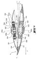
- Figure 2 in particular shows a top view, in section, of a ploughshare discs according to the invention.
- the section is taken according to plans orthogonal to each disc (8; 9) and passing through their axis of rotation (8a; 9a).
- the plans of cuts are therefore inclined relative to each other.
- the discs, main (8) and secondary (9) have a shape substantially concave.
- the discs (8, 9) also join at their periphery by going into the direction of travel (F), i.e. towards the front of the coulter.
- the main disc (8; 108; 208; 308; 408) is mounted on the support member (7; 107; 207; 307; 407) using mounting means comprising a main bearing (20; 120; 220; 320; 420) fixed on said disc main (8; 108; 208; 308; 408), a main axis (25; 125; 225; 325; 425), and a bearing (23; 123; 223; 323; 423) which provides the interface between said bearing (20; 120; 220; 320; 420) and said main axis (25; 125; 225; 325; 425).
- mounting means comprising a main bearing (20; 120; 220; 320; 420) fixed on said disc main (8; 108; 208; 308; 408), a main axis (25; 125; 225; 325; 425), and a bearing (23; 123; 223; 323; 423) which provides the interface between said bearing (20; 120; 220; 320;
- the secondary disc (9; 109; 209; 309; 409; 509; 609) is mounted on the support member (7; 107; 207; 307; 407) using mounting means comprising a secondary bearing (21; 121; 221; 321; 421; 521; 621) fixed on said secondary disc (9; 109; 209; 309; 409; 509; 609), a secondary axis (26-26a-27; 126-126a-127; 226-226a-227; 326-326a-327; 426-426a-427) and a bearing (24; 124; 224; 324; 424; 524; 624), which provides the interface between said bearing (21; 121; 221; 321; 421; 521; 621) and said secondary axis (26-26a-27 ; 126-126a-127; 226-226a-227; 326-326a-327; 426-426a-427).
- the main disc (8) and the secondary disc (9) are provided respectively the main bearing (20) and the secondary bearing (21).
- Each level (20, 21) is fixed on its respective disc (8, 9), using means such as screws fixing (22).
- the bearings (20, 21) have suitable housings for position bearings, for example ball bearings or ball bearings (23, 24) rollers, which respectively interface with a main axis (25) and secondary (26), centered on the main axes of rotation (8a) and secondary (9a).
- the bearings (23) and (24) are advantageously locked between the bearings (20, 21) and the respective discs (8, 9).
- a mounting part (27) is for example attached and fixed to the secondary axis (26), using an additional screw (26a).
- the secondary axis (26) is fixed on the support member (7) and present by example a rectangular or circular cross section.
- the secondary axis (26) also has a particular orientation to give orientation optimal to the secondary disc (9) and thus to cooperate with the main disc (8).
- the mounting piece (27) has a configuration allowing it to receive the bearing (24).
- the mounting part (27) is also machined from so as to retain a stop ring (28), which serves to lock the bearing (24).
- the secondary disc (9) and the secondary bearing (21) therefore constitute a sub-assembly turning around the axis of rotation (9a), during sowing work.
- the secondary disc (9) is therefore mounted on the support member (7) using mounting means comprising, the bearing (21) fixed on said secondary disc (9), the secondary axis (26) associated with the mounting part (27) and the bearing (24) providing the interface between said mounting part (27) and the bearing (21).
- Another stop ring (29) is for example used to block the bearing on the main axis (25). Such an arrangement is known as such.
- FIG. 2 also shows a material for example resistant to abrasion, attached to one of the discs (8, 9) so as to substantially obstruct access to the internal volume defined by said discs (8, 9).
- the material in question, in the occurrence the shutter member (31), for example has a configuration of the ring type, arranged in the vicinity of the inner periphery of the main disc (8).
- the periphery of the secondary disc (9) comes into contact, or almost in contact with the shutter member (31) so as to close the attack zone (A) disc coulter. Earth and / or debris is therefore prevented from plants to penetrate between the discs (8, 9).
- the shutter member (31) is by example fixed on the main disc (8) by any known means and in particular by, bonding, vulcanization, riveting or screwing.
- the shutter member (31) has a shape adapted to the concave shape of the secondary disc (9; 109; 209; 309), so as not to alter a rotation of said secondary disc (9; 109; 209; 309), relative to the main disc (8).
- At least one of the mounting means also includes elastic means (132; 232; 332; 632) allowing the corresponding disc to deviate from the other disc of the share.
- the elastic means (132) consists of an elastic ring of the type "silentbloc" that includes the corresponding axis (126-126a-127-132).
- the way elastic (232; 632) can also constitute part of the bearing (221; 621) corresponding.
- the elastic means (332) constitutes the corresponding bearing (321) in its entirety.
- the means mounting the secondary disc (109; 209; 309; 609) which include the elastic means (132; 232; 332; 632).
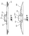
- FIG. 3 in particular represents another embodiment for a disc share according to the invention, in which at least one of the means for mounting the secondary disc (109) also includes the elastic means (132) allowing the secondary disc (109) to deviate elastically relative to to the main disc (108).
- the elastic means (132) (FIG. 3) makes the connection between a core (127a) and a central part (127b) of the mounting piece (127).
- the central part (127b) is secured with an envelope (127c) on which the bearing is mounted (124).
- the elastic means (132) consists for example of a material of the elastomer type.
- the elasticity and flexibility sought after mounting are therefore integrated in the mounting part (127) and allow the secondary disc (109), under the effect of constraints, to move away from the main disc (108) along the axis of rotation (109a) and / or along an axis perpendicular to the axis of rotation (109a).
- the elastic means (132) also ensures optimum closure of the zone (A), in which the periphery of the secondary disc (109) can exert low pressure on the shutter member (131).
- the elastic means (232) is directly integrated into the bearing (221).
- the latter therefore presents a part central (221a) surrounding the bearing (224), which is mounted on the workpiece mounting (227).
- the peripheral part of the bearing (221) is fixed on the disc secondary (209) using screws (222) and has for this purpose sufficient rigidity.
- the central part (221a) is also made with a rigid material.
- the way elastic (232) in this case is made of a material capable of binding in a way intimate the rigid parts of the bearing (221).
- the flexibility of the elastic means (232) thus allows the secondary disc (209) to move away from the main disc (208), the central part (221a) being only allowed to rotate around the axis of rotation (209a).
- the elastic means (232) has for example an annular shape.
- the bearing (321) itself constitutes the elastic means (332).
- the bearing (321) therefore consists entirely of a flexible material.
- the bearing (321) has for this purpose sufficient elasticity to allow spacing of the secondary disk (309).
- the fixing screws (322) are advantageously associated with rigid tubular inserts (322a), for fixing intimately the bearing (321) on the secondary disc (309).
- the head of each fixing screw (322) rests on the secondary disc (309) and the attached nut on said screw (322) bears on the tubular insert (322a), while maintaining places the bearing (321).
- Elastic and reversible deformation of the bearing (321) thus allows the secondary disc (309) to move apart while retaining a mount closes the mounting part (327), associated with the bearing (324), on the axis secondary (326).
- This solution has the advantage that one can directly overmold the bearing (324) on the bearing (321).
- the secondary disc (409) is provided at its periphery with a annular tongue, advantageously resistant to abrasion on the one hand and flexible or flexible on the other hand.
- the obturation member (431) thus consists of a lip or a tab at the periphery of the corresponding disc (409).
- the tongue is preferably fixed on the secondary disc (409) by all known means, and in particular by gluing.
- the use of such a tab or lip for the obturation member (431) authorizes mounting of the secondary disc (409) without the use of an additional elastic means.
- FIG. 7 represents a secondary disc (509) of planar shape and circular.
- the shutter member (531), made of a flexible material, is attached on the periphery of said disc (509) by any known means.
- the rigid bearing (521) is fixed and centered using screws (522) or rivets (Figure 7) on the outer face of the secondary disc (509), said outer face coming with a peripheral strip, partially in contact with a wall of the groove (11).
- the ring (531) is attached to the other face, located opposite the disc main (not shown in this example).
- Figure 8 shows another example to make the disc share according to the invention.
- the secondary disc (609) consists of the bearing (621), central, supporting the bearing (624). The latter is locked in position thanks to the stop ring (628).
- a hat (621a) allows cover the bearing mounting area (624).
- the bearing (621) is secured to the elastic means (632), which surrounds said bearing (621).
- the rigid periphery of the secondary disc (609) is glued or fixed by all means on the periphery of the elastic means (632).
- the example shown in Figure 8 shows a rigid periphery of substantially concave shape or more precisely substantially frustoconical.
- the rigid periphery, which comes in contact with a wall of the groove (11) is therefore liable to deviate from the main disc (not shown in this figure), following a deformation of said main disc or the presence of stones or other debris may get caught between discs.
- the elasticity of the interface (elastic means (632)), between the rigid periphery and the bearing (621) makes it possible to obtain a optimal functioning and excellent adaptation to working conditions variety.
- the abrasion-resistant material in particular the sealing member (31; 131; 231; 331; 431; 531) is for example made of polyurethane.
- other known materials for example flexible or flexible, may also be suitable without departing from the scope of the present invention.
- Discs (8; 108; 208; 308; 408; 9; 109; 209; 309; 409; 509; 609) where their rigid part (s) are preferably metallic, but others rigid materials preferably not subject to abrasion may also be suitable.
Landscapes
- Life Sciences & Earth Sciences (AREA)
- Soil Sciences (AREA)
- Environmental Sciences (AREA)
- Sowing (AREA)
- Soil Working Implements (AREA)
- Steroid Compounds (AREA)
- Apparatuses For Bulk Treatment Of Fruits And Vegetables And Apparatuses For Preparing Feeds (AREA)
Applications Claiming Priority (2)
| Application Number | Priority Date | Filing Date | Title |
|---|---|---|---|
| FR9714001A FR2770367B1 (fr) | 1997-11-04 | 1997-11-04 | Soc a disques pour semoirs |
| FR9714001 | 1997-11-04 |
Publications (2)
| Publication Number | Publication Date |
|---|---|
| EP0914763A1 EP0914763A1 (fr) | 1999-05-12 |
| EP0914763B1 true EP0914763B1 (fr) | 2003-03-05 |
Family
ID=9513142
Family Applications (1)
| Application Number | Title | Priority Date | Filing Date |
|---|---|---|---|
| EP98440247A Expired - Lifetime EP0914763B1 (fr) | 1997-11-04 | 1998-11-02 | Soc à disques pour semoirs |
Country Status (8)
| Country | Link |
|---|---|
| US (1) | US6082276A (da) |
| EP (1) | EP0914763B1 (da) |
| AT (1) | ATE233471T1 (da) |
| CA (1) | CA2250378A1 (da) |
| DE (1) | DE69811822T2 (da) |
| DK (1) | DK0914763T3 (da) |
| ES (1) | ES2190052T3 (da) |
| FR (1) | FR2770367B1 (da) |
Families Citing this family (25)
| Publication number | Priority date | Publication date | Assignee | Title |
|---|---|---|---|---|
| CA2265367C (en) * | 1999-03-16 | 2003-12-30 | Fred Harrison | Furrow opening disc apparatus |
| FR2806870B1 (fr) | 2000-03-28 | 2002-12-13 | Kuhn Sa | Dispositif d'implantation de graines dans le sol et semoir equipe de tels dispositifs |
| US6454019B1 (en) * | 2000-06-28 | 2002-09-24 | Case Corporation | Agricultural implement down pressure system |
| FR2811195B1 (fr) | 2000-07-07 | 2003-01-17 | Kuhn Sa | Dispositif de verrouillage d'un capot d'une machine de travail du sol |
| DE10247569B3 (de) * | 2002-10-11 | 2004-05-19 | Kverneland Asa | Säschar |
| US6913085B2 (en) * | 2003-05-14 | 2005-07-05 | Deere & Company | Single standard double disk configuration |
| NL1026442C2 (nl) * | 2004-06-17 | 2005-12-20 | Redexim Handel En Expl Mij B V | Grondbewerkinrichting en werkwijze voor het aanbrengen van zaden in bewerkte grond. |
| ES1069673Y (es) * | 2009-02-16 | 2009-08-03 | Bellota Herramientas Sa | Amarre rapido de discos en gradas |
| SE533877C2 (sv) | 2009-05-29 | 2011-02-15 | Vaederstad Verken Ab | Tallrik för ett lantbruksredskap |
| DE102011051026B3 (de) * | 2011-06-10 | 2012-11-08 | Kverneland Asa | Flexible Scheibe für Scheibensäschar |
| US8794345B2 (en) | 2011-08-11 | 2014-08-05 | Cnh Industrial America Llc | Strip-till no build-up berm builder blade for strip-till farm implement |
| GB2498530B (en) * | 2012-01-17 | 2017-05-17 | Frank Weaving Edward | No till seed drill |
| EP2732685B1 (de) * | 2012-11-19 | 2016-06-01 | Horsch Maschinen GmbH | Doppelscheibenschar einer landwirtschaftlichen Maschine, insbesondere einer Sämaschine |
| US20140299343A1 (en) * | 2013-04-04 | 2014-10-09 | Douglas G. Bruce | Disc and Coulter with Center Depression for Strength |
| DE102013007234A1 (de) | 2013-04-26 | 2014-10-30 | Lemken Gmbh & Co. Kg | Doppelscheibenschar |
| CN103392395B (zh) * | 2013-07-03 | 2016-03-09 | 青岛璞盛机械有限公司 | 一种郁金种植机 |
| CA2891695A1 (en) * | 2014-05-19 | 2015-11-19 | Aktiebolaget Skf | Hub-bearing assembly for an agricultural tilling disc |
| US9763379B2 (en) | 2015-06-30 | 2017-09-19 | Cnh Industrial America Llc | Replaceable wear insert for a forming point positioned between furrow opening disks |
| DE102015118640A1 (de) * | 2015-10-30 | 2017-05-04 | Lemken Gmbh & Co. Kg | Andruckrolle für eine landwirtschaftliche Sämaschine |
| US10842063B2 (en) * | 2018-02-07 | 2020-11-24 | Deere & Company | Tillage machine and tillage disk for the same |
| CN109874425A (zh) * | 2019-04-11 | 2019-06-14 | 贵州大学 | 一种免耕防堵开沟器 |
| CA3077758A1 (en) * | 2019-04-15 | 2020-10-15 | Cnh Industrial America Llc | Variable angle disc hub for a tiller jump arm assembly |
| US11540434B2 (en) * | 2019-10-15 | 2023-01-03 | Cnh Industrial America Llc | Curved cultivating disc with a straight cutting edge portion |
| CN113207334B (zh) * | 2021-05-13 | 2022-06-14 | 青海大学 | 一种利用牛粪进行种子覆盖施肥的草地种植设备 |
| CN113994797B (zh) * | 2021-11-12 | 2025-01-21 | 东北农业大学 | 螺旋驱动往复滑移式精量排种器 |
Family Cites Families (25)
| Publication number | Priority date | Publication date | Assignee | Title |
|---|---|---|---|---|
| US522329A (en) * | 1894-07-03 | Frank r | ||
| US605348A (en) * | 1898-06-07 | Walter w | ||
| US603863A (en) * | 1898-05-10 | William stephenson | ||
| US501917A (en) * | 1893-07-25 | Cleaner for cultivator-disks | ||
| US736963A (en) * | 1902-12-29 | 1903-08-25 | Rude Brothers Mfg Company | Double-disk furrow-opener. |
| US735815A (en) * | 1903-04-13 | 1903-08-11 | Octave A Poirier | Bearing for drill devices. |
| US883304A (en) * | 1907-05-31 | 1908-03-31 | E G Powell | Cultivator attachment for thinning cotton. |
| US990654A (en) * | 1910-02-03 | 1911-04-25 | American Drill Company | Double-disk furrow-opener. |
| US1124006A (en) * | 1912-09-27 | 1915-01-05 | John W Gallespie | Scraper. |
| US1104725A (en) * | 1913-08-12 | 1914-07-21 | Aspinwall Mfg Company | Potato-planter. |
| US2730940A (en) * | 1953-07-07 | 1956-01-17 | Be Ge Mfg Co | Scraper blade for reversible disc plows |
| US2924189A (en) * | 1955-09-02 | 1960-02-09 | Deere & Co | Sod mulcher for grain drills |
| US2815991A (en) * | 1956-05-25 | 1957-12-10 | Frank J Stoffel | Nylon disc bearings for grain drills |
| GB819053A (en) * | 1956-07-21 | 1959-08-26 | Weiste Heinrich | Improved planting machine for agricultural use |
| US2917012A (en) * | 1957-01-29 | 1959-12-15 | Deere & Co | Disk fertilizer furrow opener attachment for planters |
| US3058531A (en) * | 1959-09-23 | 1962-10-16 | John B Beaman | Twin shear disc tool for mulching and the like |
| FR2413864A1 (fr) * | 1978-01-06 | 1979-08-03 | Huard Ucf | Perfectionnements aux dispositifs semeurs |
| US4493274A (en) * | 1980-05-28 | 1985-01-15 | International Harvester Company | Furrow forming apparatus for a seed planter |
| US4337835A (en) * | 1981-01-23 | 1982-07-06 | Deere & Company | Scraper for double disk furrow opener |
| US4736803A (en) * | 1986-09-16 | 1988-04-12 | J. I. Case Company | Self-adjusting scrapers for double disk openers |
| DE9219030U1 (de) * | 1992-07-22 | 1997-01-23 | Accord-Landmaschinen Heinrich Weiste & Co., Gesellschaft mit beschränkter Haftung, 59494 Soest | Zweischeibenschar mit Topfscheibe |
| US5724902A (en) * | 1994-03-14 | 1998-03-10 | Universite Laval Of Cite Universitaire | Minimum tillage seeding device |
| US5678500A (en) * | 1995-09-01 | 1997-10-21 | Montezuma Welding & Mfg., Inc. | Seed delivery device for seed planter |
| DE19541874C2 (de) * | 1995-11-09 | 1999-02-18 | Kleine Franz Maschf | Sägerät, insbesondere für die Mulch- und/oder Direktsaat |
| DE29801820U1 (de) * | 1998-02-04 | 1998-05-07 | Kverneland Accord GmbH & Co. KG, 59494 Soest | Zweischeibenschar |
-
1997
- 1997-11-04 FR FR9714001A patent/FR2770367B1/fr not_active Expired - Fee Related
-
1998
- 1998-10-27 US US09/179,191 patent/US6082276A/en not_active Expired - Fee Related
- 1998-10-28 CA CA002250378A patent/CA2250378A1/fr not_active Abandoned
- 1998-11-02 DE DE69811822T patent/DE69811822T2/de not_active Expired - Lifetime
- 1998-11-02 DK DK98440247T patent/DK0914763T3/da active
- 1998-11-02 ES ES98440247T patent/ES2190052T3/es not_active Expired - Lifetime
- 1998-11-02 EP EP98440247A patent/EP0914763B1/fr not_active Expired - Lifetime
- 1998-11-02 AT AT98440247T patent/ATE233471T1/de active
Also Published As
| Publication number | Publication date |
|---|---|
| FR2770367A1 (fr) | 1999-05-07 |
| DK0914763T3 (da) | 2003-06-30 |
| FR2770367B1 (fr) | 2000-01-28 |
| ES2190052T3 (es) | 2003-07-16 |
| DE69811822T2 (de) | 2003-12-11 |
| EP0914763A1 (fr) | 1999-05-12 |
| DE69811822D1 (de) | 2003-04-10 |
| ATE233471T1 (de) | 2003-03-15 |
| US6082276A (en) | 2000-07-04 |
| CA2250378A1 (fr) | 1999-05-04 |
Similar Documents
| Publication | Publication Date | Title |
|---|---|---|
| EP0914763B1 (fr) | Soc à disques pour semoirs | |
| FR2923348A1 (fr) | Machine agricole, notamment semoir equipe d'un systeme adaptable et perfectionne de scarification du sol. | |
| US6874584B2 (en) | Disc furrow opener scraper positioning system | |
| EP3834594A1 (fr) | Roue racleuse pour semoir | |
| EP3549420B1 (fr) | Unité d'enfouissement de produit agricole et machine agricole comportant une telle unité | |
| FR2727601A1 (fr) | Semoir a element semeur associe a un etancon equipe d'un organe de coupe qui ouvre un sillon | |
| EP2168415B1 (fr) | Dispositif de recouvrement perfectionné | |
| EP2563108B1 (fr) | Ensemble semeur pour semoir | |
| FR2979178A1 (fr) | Appareil agricole de travail du sol, notamment semoir equipe de socs discoidaux d'ensemencement | |
| CA2411041C (en) | Disc furrow opener scraper positioning system | |
| EP0387110B1 (fr) | Dispositif de réglage de la profondeur des semis | |
| EP0974253B1 (fr) | Semoir | |
| EP0974252B1 (fr) | Semoir | |
| EP0682854B1 (fr) | Rouleau de travail du sol à usage agricole et machine agricole utilisant un tel rouleau | |
| EP1787503B1 (fr) | Combiné de semis | |
| EP4059334B1 (fr) | Dispositif de raclage pour deux disques de machine agricole et machine agricole associée | |
| FR2788657A1 (fr) | Ensemble constitue d'un dispositif de depot de grains et d'une roue plombeuse, et semoir ainsi equipe | |
| FR3096867A1 (fr) | Bras amélioré pour dispositif de semis direct | |
| FR3138599A3 (fr) | Bras de semis pour machine à semer | |
| FR2570922A1 (fr) | Distributeur de graines combine a une roue a godets de plastisemeuse. | |
| FR2842066A1 (fr) | Semoir agricole comportant un dispositif de reglage du terrage centralise | |
| OA21725A (fr) | Roue semeuse monograine multifonction pour l'épandage et l'ensemencement. | |
| FR3111763A1 (fr) | Semoir réglable | |
| FR2756450A1 (fr) | Dispositif de localisation dans le sol de matieres granuleuses telles que graines de cereales ou engrais | |
| FR2881020A1 (fr) | Element de semoir et semoir correspondant |
Legal Events
| Date | Code | Title | Description |
|---|---|---|---|
| PUAI | Public reference made under article 153(3) epc to a published international application that has entered the european phase |
Free format text: ORIGINAL CODE: 0009012 |
|
| AK | Designated contracting states |
Kind code of ref document: A1 Designated state(s): AT BE DE DK ES FR GB IT NL |
|
| AX | Request for extension of the european patent |
Free format text: AL;LT;LV;MK;RO;SI |
|
| 17P | Request for examination filed |
Effective date: 19991020 |
|
| AKX | Designation fees paid |
Free format text: AT BE DE DK ES FR GB IT NL |
|
| GRAG | Despatch of communication of intention to grant |
Free format text: ORIGINAL CODE: EPIDOS AGRA |
|
| GRAG | Despatch of communication of intention to grant |
Free format text: ORIGINAL CODE: EPIDOS AGRA |
|
| 17Q | First examination report despatched |
Effective date: 20020322 |
|
| GRAG | Despatch of communication of intention to grant |
Free format text: ORIGINAL CODE: EPIDOS AGRA |
|
| GRAH | Despatch of communication of intention to grant a patent |
Free format text: ORIGINAL CODE: EPIDOS IGRA |
|
| GRAH | Despatch of communication of intention to grant a patent |
Free format text: ORIGINAL CODE: EPIDOS IGRA |
|
| GRAA | (expected) grant |
Free format text: ORIGINAL CODE: 0009210 |
|
| AK | Designated contracting states |
Designated state(s): AT BE DE DK ES FR GB IT NL |
|
| REG | Reference to a national code |
Ref country code: GB Ref legal event code: FG4D Free format text: NOT ENGLISH |
|
| REF | Corresponds to: |
Ref document number: 69811822 Country of ref document: DE Date of ref document: 20030410 Kind code of ref document: P |
|
| REG | Reference to a national code |
Ref country code: DK Ref legal event code: T3 |
|
| GBT | Gb: translation of ep patent filed (gb section 77(6)(a)/1977) | ||
| REG | Reference to a national code |
Ref country code: ES Ref legal event code: FG2A Ref document number: 2190052 Country of ref document: ES Kind code of ref document: T3 |
|
| PLBE | No opposition filed within time limit |
Free format text: ORIGINAL CODE: 0009261 |
|
| STAA | Information on the status of an ep patent application or granted ep patent |
Free format text: STATUS: NO OPPOSITION FILED WITHIN TIME LIMIT |
|
| 26N | No opposition filed |
Effective date: 20031208 |
|
| REG | Reference to a national code |
Ref country code: FR Ref legal event code: PLFP Year of fee payment: 18 |
|
| REG | Reference to a national code |
Ref country code: FR Ref legal event code: PLFP Year of fee payment: 19 |
|
| PGFP | Annual fee paid to national office [announced via postgrant information from national office to epo] |
Ref country code: DK Payment date: 20161021 Year of fee payment: 19 Ref country code: NL Payment date: 20161024 Year of fee payment: 19 Ref country code: GB Payment date: 20161027 Year of fee payment: 19 |
|
| PGFP | Annual fee paid to national office [announced via postgrant information from national office to epo] |
Ref country code: ES Payment date: 20161024 Year of fee payment: 19 Ref country code: BE Payment date: 20161024 Year of fee payment: 19 |
|
| REG | Reference to a national code |
Ref country code: FR Ref legal event code: PLFP Year of fee payment: 20 |
|
| PGFP | Annual fee paid to national office [announced via postgrant information from national office to epo] |
Ref country code: FR Payment date: 20171020 Year of fee payment: 20 Ref country code: DE Payment date: 20171019 Year of fee payment: 20 |
|
| PGFP | Annual fee paid to national office [announced via postgrant information from national office to epo] |
Ref country code: AT Payment date: 20171020 Year of fee payment: 20 Ref country code: IT Payment date: 20171020 Year of fee payment: 20 |
|
| REG | Reference to a national code |
Ref country code: DK Ref legal event code: EBP Effective date: 20171130 |
|
| REG | Reference to a national code |
Ref country code: NL Ref legal event code: MM Effective date: 20171201 |
|
| GBPC | Gb: european patent ceased through non-payment of renewal fee |
Effective date: 20171102 |
|
| REG | Reference to a national code |
Ref country code: BE Ref legal event code: MM Effective date: 20171130 |
|
| PG25 | Lapsed in a contracting state [announced via postgrant information from national office to epo] |
Ref country code: NL Free format text: LAPSE BECAUSE OF NON-PAYMENT OF DUE FEES Effective date: 20171201 |
|
| REG | Reference to a national code |
Ref country code: DE Ref legal event code: R071 Ref document number: 69811822 Country of ref document: DE |
|
| PG25 | Lapsed in a contracting state [announced via postgrant information from national office to epo] |
Ref country code: BE Free format text: LAPSE BECAUSE OF NON-PAYMENT OF DUE FEES Effective date: 20171130 Ref country code: DK Free format text: LAPSE BECAUSE OF NON-PAYMENT OF DUE FEES Effective date: 20171130 Ref country code: GB Free format text: LAPSE BECAUSE OF NON-PAYMENT OF DUE FEES Effective date: 20171102 |
|
| REG | Reference to a national code |
Ref country code: AT Ref legal event code: MK07 Ref document number: 233471 Country of ref document: AT Kind code of ref document: T Effective date: 20181102 |
|
| REG | Reference to a national code |
Ref country code: ES Ref legal event code: FD2A Effective date: 20181221 |
|
| PG25 | Lapsed in a contracting state [announced via postgrant information from national office to epo] |
Ref country code: ES Free format text: LAPSE BECAUSE OF NON-PAYMENT OF DUE FEES Effective date: 20171103 |