EP0913596A2 - Reinigbarer Betätiger - Google Patents
Reinigbarer Betätiger Download PDFInfo
- Publication number
- EP0913596A2 EP0913596A2 EP98850164A EP98850164A EP0913596A2 EP 0913596 A2 EP0913596 A2 EP 0913596A2 EP 98850164 A EP98850164 A EP 98850164A EP 98850164 A EP98850164 A EP 98850164A EP 0913596 A2 EP0913596 A2 EP 0913596A2
- Authority
- EP
- European Patent Office
- Prior art keywords
- bearing surface
- surface means
- bearing
- lobes
- spool
- Prior art date
- Legal status (The legal status is an assumption and is not a legal conclusion. Google has not performed a legal analysis and makes no representation as to the accuracy of the status listed.)
- Withdrawn
Links
- 238000004140 cleaning Methods 0.000 description 14
- 238000005202 decontamination Methods 0.000 description 9
- 230000003588 decontaminative effect Effects 0.000 description 9
- 239000007788 liquid Substances 0.000 description 8
- 230000001954 sterilising effect Effects 0.000 description 7
- 238000004659 sterilization and disinfection Methods 0.000 description 7
- 239000003206 sterilizing agent Substances 0.000 description 6
- 230000000249 desinfective effect Effects 0.000 description 5
- 238000000034 method Methods 0.000 description 5
- 239000000306 component Substances 0.000 description 4
- 239000000356 contaminant Substances 0.000 description 4
- 230000007246 mechanism Effects 0.000 description 3
- 229920001971 elastomer Polymers 0.000 description 2
- 238000009825 accumulation Methods 0.000 description 1
- 239000003708 ampul Substances 0.000 description 1
- 239000003795 chemical substances by application Substances 0.000 description 1
- 239000012459 cleaning agent Substances 0.000 description 1
- 238000004891 communication Methods 0.000 description 1
- 230000000295 complement effect Effects 0.000 description 1
- 238000010276 construction Methods 0.000 description 1
- 238000011109 contamination Methods 0.000 description 1
- 239000000806 elastomer Substances 0.000 description 1
- 239000012530 fluid Substances 0.000 description 1
- 238000002955 isolation Methods 0.000 description 1
- 239000000463 material Substances 0.000 description 1
- 239000005426 pharmaceutical component Substances 0.000 description 1
- 238000007789 sealing Methods 0.000 description 1
- -1 vials Substances 0.000 description 1
- 238000005406 washing Methods 0.000 description 1
- XLYOFNOQVPJJNP-UHFFFAOYSA-N water Substances O XLYOFNOQVPJJNP-UHFFFAOYSA-N 0.000 description 1
Images


Classifications
-
- F—MECHANICAL ENGINEERING; LIGHTING; HEATING; WEAPONS; BLASTING
- F16—ENGINEERING ELEMENTS AND UNITS; GENERAL MEASURES FOR PRODUCING AND MAINTAINING EFFECTIVE FUNCTIONING OF MACHINES OR INSTALLATIONS; THERMAL INSULATION IN GENERAL
- F16C—SHAFTS; FLEXIBLE SHAFTS; ELEMENTS OR CRANKSHAFT MECHANISMS; ROTARY BODIES OTHER THAN GEARING ELEMENTS; BEARINGS
- F16C17/00—Sliding-contact bearings for exclusively rotary movement
- F16C17/26—Systems consisting of a plurality of sliding-contact bearings
Definitions
- the invention relates to guide bearings that are suited for use with machinery that operates in whole or in part in a clean environment, and which may be thoroughly cleaned and decontaminated or sterilized prior to and after use.
- Such machinery may, for example, be used for processing pharmaceutical components (e.g., vials, ampules or syringes) or in connection with food processing.
- Machinery of this type necessarily operates in a clean environment, either by placing the entirety of the machine in a clean room or by defining a clean or isolation zone within the machine itself in which the processing operations take place.
- the various processing operations are typically accomplished through the use of mechanical apparatus that includes both stationary and moving components.
- mechanical apparatus that includes both stationary and moving components.
- the subject invention is the result of an endeavor to develop linear and rotary guide bearings usable within the clean zone of a processing machine which not only provide the intended guiding function but which are also easily cleanable in their entirety.
- the inventive bearings of the preferred embodiment are disclosed in conjunction with a machine that performs one step in a hypodermic syringe filling operation, but the inventive principle itself has wider application.
- the inventive bearing of the preferred embodiment specifically takes the form of a pair of spool members carried on a reciprocating shaft that are axially spaced by a predetermined distance.
- Each of the spools has an associated guide bearing surface, which in the preferred embodiment takes the form of a cylindrical bore formed in a member which is stationary in relation to the movable spool.
- the cylindrical bores are also axially spaced but by an amount that is greater than the axial spacing between the two spool members.
- This relative axial spacing is chosen so that both spool members may be in partial guided engagement with the associated guide bearing surfaces with the actuator shaft in an intermediate position. but when the shaft is in either of its extreme positions, one spool member is in complete engagement with its associated guide bearing surface while the other spool member is moved entirely out of engagement with its associated guide surface. In the opposite extreme position, the spool members are conversely positioned.
- This component arrangement ensures that the linearly moving actuator shaft is always in guided engagement by one or both spool members, thus providing the necessary guiding function.
- the spool which is in the free position and its associated guide bearing surface may be cleaned and decontaminated or sterilized in their entirety with a disinfecting solution or sterilizing agent. and with the actuator shaft moved to its opposite limit position, the other spool member and its associated guide bearing surface may be cleaned and decontaminated or sterilized in the same manner.
- the inventive principle also is applicable to rotary guide bearings.
- the preferred embodiment of this device takes the form of a rotatable shaft disposed within a guide housing.
- the shaft includes first and second spools, with each spool defining at least two radially outwardly projecting lobes (four equiangularly spaced lobes in the preferred embodiment).
- the guide housing includes a like number of radially inwardly projecting guide surfaces. With the lobes in guided contact with the associated guide bearing surfaces, fluid communication (e.g., passages for disinfecting liquid or a sterilizing agent) exists only through spaces between the lobes.
- the second spool is axially spaced from the first spool and has the same structural configuration. However, its lobes are angularly disposed in a staggered arrangement relative to the lobes of the first spool; e.g., the four lobes of one spool are disposed at a relative angular difference of 45° to the other. Stated otherwise, when the lobes of the first spool are in full engagement with the associated guide surfaces, the lobes of the second spool have moved entirely out of engagement with their associated guide bearing surfaces.
- the rotary bearing operates in the same manner as the reciprocating bearing.
- the "free" spool and its associated guide bearing surfaces may be cleaned and decontaminated or sterilized with the shaft in the first position, and when the shaft is rotated to a second position (e.g., 45° for four-lobed spools), the other spool may be cleaned and decontaminated or sterilized in its entirety.
- the inventive guide bearings are simple in construction. but provide the necessary guiding function throughout all phases of operation. Most importantly, they are capable of being cleaned and decontaminated in their entirety by moving the actuator from one limit position to the other during the cleaning process.
- a machine module bearing the general reference numeral 11 is constructed to perform one step in the process of assembling hypodermic syringes 12.
- Machine 11 is of the rotary type, and its specific function is to insert a resilient plunger into the barrel or reservoir of the syringe 12 which has already been filled with liquid.
- the syringes 12 are conventionally carried to the rotary machine 11 by a transport system (not shown) which brings each syringe 12 to an initial position (see the right-hand side of FIG. 2).
- the syringe 12 then moves in a rotary motion with machine 11 until the plunger has been inserted (see the left-hand side of FIG. 2), after which it leaves machine 11 and is transported for further processing. It is to be understood that the entire process takes place within a clean, decontaminated room, or within an isolated space within the machine which is clean and decontaminated or sterilized.
- Rotary machine 11 includes a large, vertically disposed rotating primary shaft 1, driven by means not shown, and on which is mounted a rotating top cylindrical head 2 having a conical cap 3, a stationary middle cylindrical cam actuating section 4 having a cap 5 and a rotating lower cylindrical section 6 having a cap 7.
- the caps 3, 5, 7 cause cleaning agents to flow downward into a system drain (not shown) and prevent the accumulation of contaminants in pooled liquids.
- the entirety of rotary machine 11 as shown in Figure 2 is disposed in a clean zone.
- the syringes 12 move in a rotary manner around the machine 11, remaining in the same vertical position throughout the assembly process. Inserting the plunger (see reference numeral 35) is accomplished through the use of a vertically reciprocated tube 13 that is aligned and initially positioned immediately above the barrel or reservoir of the syringe 12 (see the right-hand side of FIG. 2).
- Each of the tubes 13 is vertically reciprocated by a mechanism including a vertical shaft 21 that is carried by and reciprocates relative to top section and lower section 6.
- Shaft 21 is formed with upper guide bearings 22a, b and lower guide bearings 23a, b.
- each of the bearings 22a, b and 23a, b takes the form of a cylindrical spool, and each is disposed for alignable, guided movement by cylindrical guide bearing surfaces 24a, b formed in head section 2 and cylindrical guide bearing surfaces 25a, b formed in lower section 6. It is possible for shaft 21 to have a continuous diameter corresponding to the spool diameter over its length, but the area of reduced diameter between spools is more efficiently cleaned.
- the distance between guide bearing surfaces 24a, b is greater than the distance between the associated spools 22a, b. It is possible during the vertical reciprocating movement of shaft 21 for both of the spools 22a, b to be in guided contact with the associated bearing surfaces 24a, b (see the left-hand side of FIG. 2), or for one of the spools to be moved out of engagement with its associated guide bearing surfaces (e.g. see spool 22b and guide bearing surface 24b on the right-hand side of FIG. 2).
- Spools 23 a, b are similarly configured with respect to their respective guide bearing surfaces 25a, b.
- Vertical shaft 21 is reciprocated by virtue of its connection to a roller bearing cam follower 27 through a step shaft 26.
- the cam follower 27 is disposed in a cam groove 28 formed in the stationary external cylindrical surface of central section 4.
- central section 4 remains stationary, causing shaft 21 to move from its highest position, as shown on the right-hand side of FIG. 2, to the lowest position, shown on the left-hand side of FIG. 2.
- Shaft 21 returns to its highest point as the revolution is completed.
- the upper end of shaft 21 is connected to a bracket member 31, the outer cantilevered end of which carries the tube 13, causing it to vertically reciprocate.
- Processing machine 11 utilizes a second vertical shaft 32 that reciprocates identically to the vertical shaft 21 by virtue of its connection to the bracket 31.
- Vertical shaft 32 is much shorter, and it is formed with a single set of guide bearings or spools 33a, b and associated cylindrical guide bearing surfaces 34a, b.
- the purpose of vertical shaft 32 is to prevent rotation of the vertical shaft 21, and hence disruptive rotational movement of the tube 13, during the process of inserting the plunger 35.
- the spacing of the spools 33a, b and guide bearing surfaces 34a, b is the same as that of spools 22a, b and guide bearing surfaces 24a, b.
- actuator shaft 21 causes a similar downward movement of tube 13 into the reservoir of syringe 12.
- the outside diameter of tube 13 is slightly less than the inside diameter of the reservoir of syringe 12.
- the purpose of apparatus 11 is to insert a compressible plunger 35 into the reservoir of each syringe 12 where it can serve to compressibly force liquid from the syringe 12.
- a plunger 35 is placed at the top end of tube 13 in a conventional manner, such as by a star wheel feeding mechanism (not shown).
- the outer diameter of plunger 35 is slightly greater than the inside diameter of the reservoir of syringe 12 and even greater than the inside diameter of tube 13.
- plunger 35 is resilient and compressible, being formed from a material such as an elastomer, and therefore is capable of being forced down through tube 13 and out of its lower end into the reservoir of syringe 12.
- the position of plunger 35 is determined by the distance tube 13 enters syringe 12, which in turn is determined as a function of the volume of liquid placed in syringe 12. In other words, the liquid that is filled into the syringe reservoir is sealed by plunger 35.
- Plunger 35 is forced into tube 13 by a small vertically reciprocating actuator rod 36 which, like tube 13, is carried at the cantilevered end of a bracket 37.
- bracket 37 is mounted at the top end of long and short vertically reciprocating actuator shafts 38, 39 that correspond in structure to the vertical actuator shafts 21, 32.
- Long actuator shaft 38 includes spaced upper guide bearings or spools 40a, b and lower spaced guide bearings or spools 41a, b. These spools respectively move in cylindrical guide bearing surfaces 42a, b and 43a, b.
- Vertical actuator shaft 38 is reciprocated by the motion of a cam follower 44 carried on a stub shaft 45 and which rides in a cam groove 46 in central section 4.
- Short actuator shaft 39 includes guide bearing spools 47a, b that respectively move in guide bearings surfaces 48a, b.
- FIG. 1 shows the relative relationship of brackets 31, 37, the inner ends of which are disposed in side-by-side rotation, and the outer ends of which overlap at a common point and move colinearly.
- FIG. 3-5 disclose the sequence of operation in inserting a plunger 35 into the barrel of one of the syringes 12.
- FIG. 3 generally corresponds to the right side of FIG. 2, showing the plunger 35 placed at the top of tube 13.
- FIG. 4 shows that both brackets 31, 37 have moved vertically downward by corresponding downward vertical movement of the two long actuator shafts 21, 38. In this position. the actuator rod 36 has engaged the plunger 35 moving it into tube 13, and tube 13 simultaneously has moved downward toward syringe 12.
- bracket 31 In FIG. 5, further downward movement of bracket 31 causes tube 13 to enter syringe 12 with its lower end at a predetermined point within the reservoir of syringe 12. Further downward movement of bracket 37 causes the short actuator rod 36 to be fully inserted into tube 13, forcing plunger 35 through and out of the lower end of tube 13 where it expands and frictionally engages the inner surface of the syringe reservoir. Air is allowed to escape through the small gap defined between tube 13 and the syringe reservoir.
- FIGs. 3-5 show only guide bearing spools 22a, b , 23a, b, 33a, b and the associated cylindrical guide bearing surfaces 24a, b, 25a, b, and 34a, b.
- the cleaning procedure is substantially the same with regard to the various guide bearings and guide bearing surfaces associated with long and short actuator shafts 38, 39. The cleaning procedure takes place before and/or after apparatus 11 is used.
- guide bearing spools 22a, 23a and 33a are all in contact with their associated guide bearing surfaces 24a, 25a and 34a. However, in this uppermost position, spools 22b, 23b and 33b have moved away from their associated guide bearing surfaces 24b, 25b and 34b. In this position, these latter spools and guide bearing surfaces can be cleaned and decontaminated or sterilized because their respective surfaces are fully exposed. Cleaning and decontamination or sterilization can be accomplished through the use of a wash such as water or another suitable washing agent, followed by a decontaminating or sterilizing agent, both of which reach the surfaces as shown by the arrows in FIG. 3.
- a wash such as water or another suitable washing agent
- apparatus 11 After cleaning and decontamination or sterilization has been accomplished in this position, apparatus 11 is moved through the position shown in FIG. 4 to the position shown in FIG. 5. At this point, spools 22a, 23a and 33a have cleared their respective guide bearing surfaces 24a, 25a and 34a, and cleaning and decontamination or sterilization can be accomplished in a manner represented by the arrows.
- apparatus 11 is constructed to permit cleaning and decontamination or sterilization of all exposed surfaces in an extremely simple manner without losing the precisely defined vertical reciprocating movement of the respective components and without the use of conventional sealing devices such as bellows that are difficult to clean and subject to wearing out.
- FIGs. 1-5 makes use of guide bearings that reciprocate or move linearly relative to associated guide bearing surfaces.
- FIGs. 6A-8C disclose an alternative embodiment in which the inventive principle is utilized in a rotary bearing.
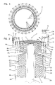
- a rotary bearing having the general reference 51 includes an upper spool 52 and a lower spool 53 interconnected by a shaft 54. Spools 52, 53 and shaft 54 are rotatable within a generally cylindrical sleeve 55.
- upper spool 52 is formed with four equiangularly spaced radially projecting lobes 56a-d having convex outer surfaces, and which are constructed and disposed for guided rotary movement by four radially inwardly projecting guide bearing surfaces 57a-d.
- Bearing surfaces 57c-d are concave and complement the convex surfaces of lobes 56a-d.
- Lower spool 53 is formed with four radially outwardly projecting lobes 58a-d that slidably engage associated guide bearing surfaces 59a-d. While the guide bearing surfaces 57a-d and 59a-d are in axial alignment, lobes 56a-d are staggered relative to lobes 58a-d, and in the preferred embodiment lobes 56a-d are disposed 45° relative to the lobes 58a-d. As such, while the lobes 56a-d are out of engagement with guide bearing surfaces 57a-d as shown in FIG. 6B, lobes 58a-d are in guided sliding engagement with guide bearing surfaces 59a-d as shown in FIG. 6C.
- shaft 54 and spools 52, 53 have been rotated clockwise 22.5°.
- lobes 56a-d of upper spool 52 are in partial guided engagement with guide bearing surfaces 57a-d (FIG. 7B)
- lobes 58a-d of lower spool 53 are also in partial guided engagement with guide bearing surfaces 59a-d (FIG. 7C).
- shaft 54 and spools 52, 53 are rotated an additional 22.5° (45° relative to the position shown in FIG. 6A). In this position, lobes 56a-d of spool 52 are in full guided engagement with guide bearings surfaces 57a-d. While lobes 58a-d of lower spool 53 have moved out of engagement with the associated guide bearing surfaces 59a-d.
- the rotary bearing 51 may be thoroughly cleaned by first placing it in the position of FIGs. 6A-6C. Disinfecting liquid or a sterilizing agent is exposed to all of the external surfaces of spool 52, including lobes 56a-d, as well as the internal exposed surfaces of sleeve 55, including guide bearing surfaces 57a-d. The disinfecting liquid or sterilizing agent passes over shaft 54 and out of the recesses defined between spool 53 and sleeve 55. Following this step, shaft 54 and spools 52, 53 are rotated 45°, through the position shown in FIGs. 7A-7C and to the position of FIGs. 8A-8C.
- the disinfecting solution or sterilizing agent enters between the spaces defined between spool 52 and sleeve 55, passes shaft 54, and then flows through the now exposed surfaces between spool 53 and sleeve 55, including the outer surfaces of lobes 58a-d and the inner exposed surfaces of guide bearing surfaces 59a-d.
Landscapes
- Engineering & Computer Science (AREA)
- General Engineering & Computer Science (AREA)
- Mechanical Engineering (AREA)
- Bearings For Parts Moving Linearly (AREA)
- Apparatus For Disinfection Or Sterilisation (AREA)
- Infusion, Injection, And Reservoir Apparatuses (AREA)
- Sliding-Contact Bearings (AREA)
Applications Claiming Priority (2)
| Application Number | Priority Date | Filing Date | Title |
|---|---|---|---|
| US958810 | 1997-10-28 | ||
| US08/958,810 US5876123A (en) | 1997-10-28 | 1997-10-28 | Cleanable actuator |
Publications (2)
| Publication Number | Publication Date |
|---|---|
| EP0913596A2 true EP0913596A2 (de) | 1999-05-06 |
| EP0913596A3 EP0913596A3 (de) | 2000-05-31 |
Family
ID=25501332
Family Applications (1)
| Application Number | Title | Priority Date | Filing Date |
|---|---|---|---|
| EP98850164A Withdrawn EP0913596A3 (de) | 1997-10-28 | 1998-10-28 | Reinigbarer Betätiger |
Country Status (4)
| Country | Link |
|---|---|
| US (1) | US5876123A (de) |
| EP (1) | EP0913596A3 (de) |
| JP (1) | JPH11217228A (de) |
| CA (1) | CA2247875C (de) |
Family Cites Families (4)
| Publication number | Priority date | Publication date | Assignee | Title |
|---|---|---|---|---|
| DE1566547A1 (de) * | 1967-01-10 | 1970-01-08 | Sickel Dr Helmut | Verfahren zum Fuellen und Verschliessen von Ampullen |
| US4975054A (en) * | 1989-04-18 | 1990-12-04 | Esrock Bernard S | Dental tool |
| US5006114A (en) * | 1990-04-20 | 1991-04-09 | Rogers Bobby E | Medical valve assembly |
| US5197954A (en) * | 1991-10-09 | 1993-03-30 | Cameron Robert W | Hypodermic syringe having folding needle |
-
1997
- 1997-10-28 US US08/958,810 patent/US5876123A/en not_active Expired - Lifetime
-
1998
- 1998-09-24 CA CA002247875A patent/CA2247875C/en not_active Expired - Fee Related
- 1998-10-28 EP EP98850164A patent/EP0913596A3/de not_active Withdrawn
- 1998-10-28 JP JP10306698A patent/JPH11217228A/ja active Pending
Non-Patent Citations (1)
| Title |
|---|
| None |
Also Published As
| Publication number | Publication date |
|---|---|
| US5876123A (en) | 1999-03-02 |
| EP0913596A3 (de) | 2000-05-31 |
| CA2247875A1 (en) | 1999-04-28 |
| JPH11217228A (ja) | 1999-08-10 |
| CA2247875C (en) | 2004-02-17 |
Similar Documents
| Publication | Publication Date | Title |
|---|---|---|
| EP0746501B1 (de) | Füllungsvorrichtung für sterile flaschen | |
| CN113825911A (zh) | 用于受控分配流体的基于蠕动泵的装置和方法 | |
| JP5433701B2 (ja) | 滅菌空間を有する容器のための閉鎖装置 | |
| US20050008730A1 (en) | Tablet press machine | |
| CN101734598A (zh) | 用于封盖容器的设备 | |
| US5876123A (en) | Cleanable actuator | |
| EP2328829B1 (de) | Behälterbehandlungsmachine, insbesondere verschliessmaschine | |
| EP0605471B1 (de) | Taumelscheibenpumpe | |
| US3776218A (en) | Apparatus for drawing liquid such as blood | |
| EP2288571B1 (de) | Behandlungsmaschine für flaschen oder dergleichen behälter | |
| US8944291B2 (en) | Dosing unit for CIP/SIP | |
| EP1604747B1 (de) | Waschvorrichtung und Ventileinrichtung mit solch einer Vorrichtung | |
| JP2005538792A (ja) | 流体スプレー装置 | |
| US20120114509A1 (en) | Dosing Apparatus with a Joint Arrangement | |
| USRE38747E1 (en) | Vial filling apparatus | |
| JP3209947B2 (ja) | 液体充填装置 | |
| US4804114A (en) | Syringe for dosed filling of bottles and the like | |
| KR900003518B1 (ko) | 축방향 다중포오트 회전밸브 | |
| JP3381096B2 (ja) | 搬送スクリュー装置 | |
| JPS62271890A (ja) | 充填装置の洗浄方法 | |
| CN120328143A (zh) | 用于移动制药用容器的旋转装置 | |
| EP4606761A1 (de) | Vorrichtung zum behandeln und/oder zum transportieren von behältern | |
| KR20240155013A (ko) | 진공채혈관 튜브 슬라이드 링크 공급 장치 | |
| SU454111A2 (ru) | Станок дл сборки и смазки | |
| IT201800009423A1 (it) | Dispositivo e apparecchiatura per l’erogazione di quantità dosate di un materiale liquido |
Legal Events
| Date | Code | Title | Description |
|---|---|---|---|
| PUAI | Public reference made under article 153(3) epc to a published international application that has entered the european phase |
Free format text: ORIGINAL CODE: 0009012 |
|
| AK | Designated contracting states |
Kind code of ref document: A2 Designated state(s): AT BE CH CY DE DK ES FI FR GB GR IE IT LI LU MC NL PT SE |
|
| AX | Request for extension of the european patent |
Free format text: AL;LT;LV;MK;RO;SI |
|
| PUAL | Search report despatched |
Free format text: ORIGINAL CODE: 0009013 |
|
| AK | Designated contracting states |
Kind code of ref document: A3 Designated state(s): AT BE CH CY DE DK ES FI FR GB GR IE IT LI LU MC NL PT SE |
|
| AX | Request for extension of the european patent |
Free format text: AL;LT;LV;MK;RO;SI |
|
| RIC1 | Information provided on ipc code assigned before grant |
Free format text: 7F 16C 17/26 A, 7F 16C 29/00 B, 7B 65B 3/00 B |
|
| 17P | Request for examination filed |
Effective date: 20001019 |
|
| AKX | Designation fees paid |
Free format text: AT BE CH CY DE DK ES FI FR GB GR IE IT LI LU MC NL PT SE |
|
| 17Q | First examination report despatched |
Effective date: 20040218 |
|
| STAA | Information on the status of an ep patent application or granted ep patent |
Free format text: STATUS: THE APPLICATION IS DEEMED TO BE WITHDRAWN |
|
| 18D | Application deemed to be withdrawn |
Effective date: 20050503 |