EP0913563B1 - Dispositif pour la ventilation d'un compartiment moteur d'un véhicule - Google Patents
Dispositif pour la ventilation d'un compartiment moteur d'un véhicule Download PDFInfo
- Publication number
- EP0913563B1 EP0913563B1 EP19980402705 EP98402705A EP0913563B1 EP 0913563 B1 EP0913563 B1 EP 0913563B1 EP 19980402705 EP19980402705 EP 19980402705 EP 98402705 A EP98402705 A EP 98402705A EP 0913563 B1 EP0913563 B1 EP 0913563B1
- Authority
- EP
- European Patent Office
- Prior art keywords
- engine
- engine compartment
- ventilate
- actuator
- intake
- Prior art date
- Legal status (The legal status is an assumption and is not a legal conclusion. Google has not performed a legal analysis and makes no representation as to the accuracy of the status listed.)
- Expired - Lifetime
Links
- 238000009423 ventilation Methods 0.000 title description 6
- 239000000428 dust Substances 0.000 claims description 7
- 238000000605 extraction Methods 0.000 claims description 3
- 210000001699 lower leg Anatomy 0.000 claims 4
- 238000001914 filtration Methods 0.000 description 2
- 230000005855 radiation Effects 0.000 description 2
- 230000004888 barrier function Effects 0.000 description 1
- 238000010276 construction Methods 0.000 description 1
- 238000001816 cooling Methods 0.000 description 1
- 230000037213 diet Effects 0.000 description 1
- 235000005911 diet Nutrition 0.000 description 1
- PCHJSUWPFVWCPO-UHFFFAOYSA-N gold Chemical compound [Au] PCHJSUWPFVWCPO-UHFFFAOYSA-N 0.000 description 1
- 239000010931 gold Substances 0.000 description 1
- 229910052737 gold Inorganic materials 0.000 description 1
- 239000002184 metal Substances 0.000 description 1
- 229910052751 metal Inorganic materials 0.000 description 1
- 238000003756 stirring Methods 0.000 description 1
Images
Classifications
-
- F—MECHANICAL ENGINEERING; LIGHTING; HEATING; WEAPONS; BLASTING
- F01—MACHINES OR ENGINES IN GENERAL; ENGINE PLANTS IN GENERAL; STEAM ENGINES
- F01M—LUBRICATING OF MACHINES OR ENGINES IN GENERAL; LUBRICATING INTERNAL COMBUSTION ENGINES; CRANKCASE VENTILATING
- F01M13/00—Crankcase ventilating or breathing
- F01M13/06—Crankcase ventilating or breathing specially adapted for submersible engines, e.g. of armoured vehicles
-
- F—MECHANICAL ENGINEERING; LIGHTING; HEATING; WEAPONS; BLASTING
- F01—MACHINES OR ENGINES IN GENERAL; ENGINE PLANTS IN GENERAL; STEAM ENGINES
- F01P—COOLING OF MACHINES OR ENGINES IN GENERAL; COOLING OF INTERNAL-COMBUSTION ENGINES
- F01P3/00—Liquid cooling
- F01P3/18—Arrangements or mounting of liquid-to-air heat-exchangers
-
- F—MECHANICAL ENGINEERING; LIGHTING; HEATING; WEAPONS; BLASTING
- F01—MACHINES OR ENGINES IN GENERAL; ENGINE PLANTS IN GENERAL; STEAM ENGINES
- F01P—COOLING OF MACHINES OR ENGINES IN GENERAL; COOLING OF INTERNAL-COMBUSTION ENGINES
- F01P1/00—Air cooling
- F01P2001/005—Cooling engine rooms
-
- F—MECHANICAL ENGINEERING; LIGHTING; HEATING; WEAPONS; BLASTING
- F01—MACHINES OR ENGINES IN GENERAL; ENGINE PLANTS IN GENERAL; STEAM ENGINES
- F01P—COOLING OF MACHINES OR ENGINES IN GENERAL; COOLING OF INTERNAL-COMBUSTION ENGINES
- F01P2031/00—Fail safe
- F01P2031/30—Cooling after the engine is stopped
-
- F—MECHANICAL ENGINEERING; LIGHTING; HEATING; WEAPONS; BLASTING
- F01—MACHINES OR ENGINES IN GENERAL; ENGINE PLANTS IN GENERAL; STEAM ENGINES
- F01P—COOLING OF MACHINES OR ENGINES IN GENERAL; COOLING OF INTERNAL-COMBUSTION ENGINES
- F01P2050/00—Applications
- F01P2050/02—Marine engines
- F01P2050/08—Engine room
-
- F—MECHANICAL ENGINEERING; LIGHTING; HEATING; WEAPONS; BLASTING
- F01—MACHINES OR ENGINES IN GENERAL; ENGINE PLANTS IN GENERAL; STEAM ENGINES
- F01P—COOLING OF MACHINES OR ENGINES IN GENERAL; COOLING OF INTERNAL-COMBUSTION ENGINES
- F01P2070/00—Details
- F01P2070/06—Using intake pressure as actuating fluid
Definitions
- the present invention relates to a device for ventilation of an engine compartment of a vehicle, engine of this vehicle being fitted with filtration dynamic intake air and fan dust extraction.
- the engine compartment of a vehicle constitutes a hot source of radiation that can help detect it and characterize.
- the concern for discretion in a situation conflict requires the reduction of such radiation, and we have already proposed to integrate a specific fan in the engine compartment for stir the air.
- This solution generates a certain number disadvantages that cannot be overcome.
- the volume dedicated to this fan additional is done at the expense of other equipment.
- the energy useful for the functioning of this fan will burden the vehicle's electrical balance, and it is essential to provide a diet electrically protected and electronically controlled.
- the cost of a fan compatible with the requirements military is high.
- US-A-3951114 describes a system for cooling of this type.
- the motor is enclosed in a compartment and a fan blows the air drawn in through an inlet duct at the level of the compartment. After stopping the engine, further ventilation while maintaining the functioning of the fan.
- This system therefore operates by vacuum.
- the object of the invention is to alleviate such disadvantages in proposing a ventilation device not using an independent fan.
- the invention provides a device for ventilation of an engine compartment of a vehicle after stopping its engine, equipped with a fan dust extraction system and a cyclonic filter of engine intake air, bypassed with the ventilator, characterized in that it consists of a means of communication interposed between the fan and the engine compartment, the operation of which is controlled by the vacuum prevailing in the circuit engine intake.
- the communication means is connected to the engine manifold through a conduit.
- the actuator is slidably attached to a fan suction nozzle.
- the actuator is in the form of a envelope with bottom, in which is engaged the end of the nozzle.
- the envelope is likely to occupy a first so-called closed position where it covers openings formed in the wall of the nozzle and a so-called position open where it releases these openings.
- the valve is in the form of a bellows elastic connected to the vacuum-controlled duct for ensure its folded position.
- the bellows is integral on either side of the bottom and nozzle.
- the bottom is provided with a vent for the passage of the air.
- the bellows is in the form of a closed flexible envelope surrounding a helical spring.
- the duct is connected to the bellows by through a screw connection at the bottom.
- a fan is simply controlled existing, without the need to intervene to ventilate the engine compartment.
- the passage of the actuator from its closed position to its open position is done automatically without any intervention, from the depression of the duct.
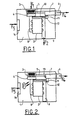
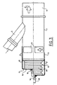
- FIGs 1 and 2 there is shown a compartment 1 in which is housed a suction motor 2 air through a cyclone box 3 according to the arrow F1.
- This box 3 is provided with a filter 4 constituting a fine dust barrier.
- This box 3 is also connected by a duct 5 with a fan 6 preceded by a nozzle 7 to evacuate large dust to outside according to arrow F4.
- Motor 2 is equipped, conventionally, an air intake manifold 8 placed downstream of the filter 4 and in which there is a vacuum depression, and manifold exhaust gas discharge 9 to the outside along arrow F2.
- a means for communication consisting of a conduit 10 and a pneumatic actuator 11.
- This duct is connected on one side to the intake manifold 8 and on the other side to the actuator 11.
- the latter is integral with the nozzle 7 and contains a valve 12.
- the assembly duct 10-actuator 11-valve 12 does not disturb its operation.
- the filtered air arriving at the cyclone 3 is directed for the most part via the nozzle 7 towards the collector 8, while a small part of this filtered air is directed to fan 6.
- the vacuum prevailing in the manifold 8 control the pneumatic actuator 11 via the line 10, and holds the valve 12 in position closed. Simultaneously fan 6 sucks in through duct 5 the air loaded with large dust which is discharged to the outside.
- FIG 3 there is shown in section a embodiment of the actuator 11 integrated into the nozzle 7.
- This nozzle 7 supports on one side the fan 6 and on the other the pneumatic actuator 11. In its part intermediate between the fan 6 and the actuator 11, the nozzle 7 receives the conduit 5 connected to the cyclone 3.
- the actuator 11 consists in this example of realization of a cylindrical envelope 15 in which an equally cylindrical part of the nozzle is engaged 7, and a bottom 16.
- the casing 15 is slidably mounted relative to nozzle 7 to occupy two positions per compared to this: a closed fallback position represented on the half-section from the top of the figure and a deployed open position shown in the half-section from the bottom of the figure.
- the nozzle 7 is provided with openings 13 which are obstructed in the fallback position of the envelope 15 and released in the deployed position. It is the bottom 16 which carries a vent 17 and receives the conduit 10 provided with a nozzle 18 via a fitting 19.
- the valve 12 here consists of a elastic metal bellows 20 constituting a sealed sealed envelope with a spring helical, subjected to depression and it is fixed on either side at the bottom 16 and at the nozzle 7.
- the vent 17 facilitates the passage of the bellows 20 from the folded position to the deployed position and vice versa.
- this is the implementation depression of the conduit 10 which passes the bellows 20 from the deployed position (lower half-cut) to the folded position (upper half-cut), after placing engine running.
- the aspiration by the conduit 10 causes the bellows 20 to fold back and causes the sliding of the casing 15 relative to the nozzle 7 according to arrow R and therefore the closing of the openings 13.
- the absence suction in the conduit 10 causes deployment along the arrow D of the bellows 20 and therefore the clearance openings 13.
- the air in engine compartment 1 is then sucked in by fan 6 through openings 13.
Landscapes
- Engineering & Computer Science (AREA)
- Mechanical Engineering (AREA)
- General Engineering & Computer Science (AREA)
- Chemical & Material Sciences (AREA)
- Combustion & Propulsion (AREA)
- Air-Conditioning For Vehicles (AREA)
- Cooling, Air Intake And Gas Exhaust, And Fuel Tank Arrangements In Propulsion Units (AREA)
Description
- les figures 1 et 2 illustrent schématiquement le fonctionnement de l'ensemble moteur d'un véhicule,
- la figure 3 est une vue en coupe illustrant la structure d'un exemple de moyen de communication.
Claims (11)
- Dispositif pour la ventilation d'un compartiment (1) moteur d'un véhicule après l'arrêt de son moteur, équipé d'un ventilateur (6) d'extraction de poussière et d'un filtre cyclonique de l'air d'admission du moteur (2), placé en dérivation avec le ventilateur, caractérisé en ce qu'il est constitué d'un moyen de communication (11, 12) interposé entre le ventilateur (6) et le compartiment moteur (1), dont le fonctionnement est commandé par la dépression régnant dans le circuit d'admission (8) du moteur.
- Dispositif pour la ventilation d'un compartiment moteur selon la revendication 1, caractérisé en ce que le moyen de communication est constitué par une soupape (12) commandant un actionneur (11), soumise à la dépression d'air.
- Dispositif pour la ventilation d'un compartiment moteur selon la revendication 2, caractérisé en ce que le moyen de communication est relié au collecteur (8) du moteur (2) par un conduit (10).
- Dispositif pour la ventilation d'un compartiment moteur selon la revendication 3, caractérisé en ce que l'actionneur (11) est fixé de manière coulissante à une buse d'aspiration (7) du ventilateur (6).
- Dispositif pour la ventilation d'un compartiment moteur selon la revendication 4, caractérisé en ce que l'actionneur (11) se présente sous la forme d'une enveloppe (15) munie d'un fond (16), dans laquelle est engagée l'extrémité de la buse (7).
- Dispositif pour la ventilation d'un compartiment moteur selon la revendication 5, caractérisé en ce que l'enveloppe (15) est susceptible d'occuper une première position dite fermée où elle recouvre des ouvertures (13) pratiquées dans la paroi de la buse (7) et une position dite ouverte où elle libère ces ouvertures (13).
- Dispositif selon la revendication 6, caractérisé en ce que la soupape (12) se présente sous la forme d'un soufflet élastique (20) relié au conduit (10) commandé en dépression pour assurer sa position repliée.
- Dispositif selon la revendication 7, caractérisé en ce que le soufflet (20) est solidaire de part et d'autre du fond (16) et de la buse (7).
- Dispositif selon la revendication 8, caractérisé en ce que le fond (16) est muni d'un évent (17) pour le passage de l'air.
- Dispositif selon la revendication 9, caractérisé en ce que le soufflet (20) se présente sous la forme d'une enveloppe souple fermée entourant un ressort hélicoïdal.
- Dispositif selon la revendication 11, caractérise en ce que le conduit (10) est connecté au soufflet (20) par l'intermédiaire d'un raccord vissé dans le fond (16).
Applications Claiming Priority (2)
| Application Number | Priority Date | Filing Date | Title |
|---|---|---|---|
| FR9713760A FR2770581B1 (fr) | 1997-11-03 | 1997-11-03 | Dispositif pour la ventilation d'un compartiment moteur d'un vehicule |
| FR9713760 | 1997-11-03 |
Publications (2)
| Publication Number | Publication Date |
|---|---|
| EP0913563A1 EP0913563A1 (fr) | 1999-05-06 |
| EP0913563B1 true EP0913563B1 (fr) | 2003-03-05 |
Family
ID=9512942
Family Applications (1)
| Application Number | Title | Priority Date | Filing Date |
|---|---|---|---|
| EP19980402705 Expired - Lifetime EP0913563B1 (fr) | 1997-11-03 | 1998-10-30 | Dispositif pour la ventilation d'un compartiment moteur d'un véhicule |
Country Status (3)
| Country | Link |
|---|---|
| EP (1) | EP0913563B1 (fr) |
| DE (1) | DE69811821T2 (fr) |
| FR (1) | FR2770581B1 (fr) |
Families Citing this family (1)
| Publication number | Priority date | Publication date | Assignee | Title |
|---|---|---|---|---|
| DE102007011452A1 (de) | 2007-03-06 | 2008-09-11 | Siemens Ag | Vorrichtung zur Vorbehandlung von Luft für ein Klimagerät eines Schienenfahrzeuges |
Family Cites Families (4)
| Publication number | Priority date | Publication date | Assignee | Title |
|---|---|---|---|---|
| US3827236A (en) * | 1972-12-18 | 1974-08-06 | D Rust | Cooling systems for turbocharger mechanisms |
| AT340720B (de) * | 1974-03-22 | 1977-12-27 | List Hans | Brennkraftmaschine mit schalldammender verschalung |
| JPS5825617U (ja) * | 1981-08-12 | 1983-02-18 | 日産自動車株式会社 | 車両のエンジンル−ム内冷却装置 |
| CA1333196C (fr) * | 1987-12-28 | 1994-11-22 | Yasuyuki Aihara | Systeme de commande de refroidissement du compartiment moteur |
-
1997
- 1997-11-03 FR FR9713760A patent/FR2770581B1/fr not_active Expired - Fee Related
-
1998
- 1998-10-30 DE DE1998611821 patent/DE69811821T2/de not_active Expired - Fee Related
- 1998-10-30 EP EP19980402705 patent/EP0913563B1/fr not_active Expired - Lifetime
Also Published As
| Publication number | Publication date |
|---|---|
| DE69811821D1 (de) | 2003-04-10 |
| FR2770581A1 (fr) | 1999-05-07 |
| EP0913563A1 (fr) | 1999-05-06 |
| DE69811821T2 (de) | 2003-11-13 |
| FR2770581B1 (fr) | 2000-01-07 |
Similar Documents
| Publication | Publication Date | Title |
|---|---|---|
| BE1001639A5 (fr) | Systeme d'admission d'air pour dispositif de propulsion marin. | |
| EP3408004B1 (fr) | Filtre à carburant et support de montage dont la sortie est obturée par un clapet en cas de retrait d'un insert filtrant | |
| EP0975482A1 (fr) | Canister de reservoir a carburant et reservoir a carburant muni d'un tel canister | |
| FR2857247A1 (fr) | Ensemble a moteur et aspirateur | |
| EP0943476B1 (fr) | Circuit de mise à l'air pour réservoir à liquide | |
| FR2533260A1 (fr) | Dispositif de refroidissement pour motocycle | |
| FR2774951A1 (fr) | Reservoir a carburant muni d'un systeme d'evacuation des gaz | |
| FR2720116A1 (fr) | Circuit de distribution de carburant à organe de ventilation. | |
| EP1614330B1 (fr) | Boitier comportant un conduit de circulation d`air empechant toute accumulation de liquide | |
| FR2595757A1 (fr) | Dispositif de separation de particules monte dans le tuyau d'echappement d'un moteur a combustion interne notamment du type diesel | |
| EP0913563B1 (fr) | Dispositif pour la ventilation d'un compartiment moteur d'un véhicule | |
| EP0415317B1 (fr) | Dispositif de sécurité anti-retour | |
| EP1899652B1 (fr) | Dispositif de ventilation d'une cuisine | |
| FR2498299A1 (fr) | Appareil pour bruleurs a huile | |
| FR2929341A1 (fr) | Dispositif d'admission d'air dans un moteur | |
| EP1112886B1 (fr) | Clapet pour réservoir à carburant de véhicule automobile | |
| EP0459866A1 (fr) | Dispositif de circuit de ventilation d'air d'un réservoir de carburant | |
| JP6551213B2 (ja) | 燃料戻し装置 | |
| FR2864437A1 (fr) | Aspirateur avec attenuation du bruit genere | |
| EP1426216B1 (fr) | Dispositif de traitement d'air compact pour véhicule automobile | |
| FR2733406A1 (fr) | Perfectionnement pour installation d'aspiration | |
| EP0344063B1 (fr) | Dispositif de dégazage à haute efficacité d'un carburant d'alimentation de moteur à combustion interne | |
| FR2711796A1 (fr) | Banc d'essai pour motocyclette ou autres engins à deux roues. | |
| FR2653074A1 (fr) | Dispositif a refouler le carburant dans un reservoir d'automobile. | |
| KR100367673B1 (ko) | 터보랙 현상 방지 장치 |
Legal Events
| Date | Code | Title | Description |
|---|---|---|---|
| PUAI | Public reference made under article 153(3) epc to a published international application that has entered the european phase |
Free format text: ORIGINAL CODE: 0009012 |
|
| AK | Designated contracting states |
Kind code of ref document: A1 Designated state(s): DE GB IT |
|
| AX | Request for extension of the european patent |
Free format text: AL;LT;LV;MK;RO;SI |
|
| 17P | Request for examination filed |
Effective date: 19991005 |
|
| AKX | Designation fees paid |
Free format text: DE GB IT |
|
| 17Q | First examination report despatched |
Effective date: 20020129 |
|
| GRAG | Despatch of communication of intention to grant |
Free format text: ORIGINAL CODE: EPIDOS AGRA |
|
| GRAG | Despatch of communication of intention to grant |
Free format text: ORIGINAL CODE: EPIDOS AGRA |
|
| GRAH | Despatch of communication of intention to grant a patent |
Free format text: ORIGINAL CODE: EPIDOS IGRA |
|
| GRAH | Despatch of communication of intention to grant a patent |
Free format text: ORIGINAL CODE: EPIDOS IGRA |
|
| GRAA | (expected) grant |
Free format text: ORIGINAL CODE: 0009210 |
|
| AK | Designated contracting states |
Designated state(s): DE GB IT |
|
| REG | Reference to a national code |
Ref country code: GB Ref legal event code: FG4D Free format text: NOT ENGLISH |
|
| GBT | Gb: translation of ep patent filed (gb section 77(6)(a)/1977) |
Effective date: 20030305 |
|
| REF | Corresponds to: |
Ref document number: 69811821 Country of ref document: DE Date of ref document: 20030410 Kind code of ref document: P |
|
| PLBE | No opposition filed within time limit |
Free format text: ORIGINAL CODE: 0009261 |
|
| STAA | Information on the status of an ep patent application or granted ep patent |
Free format text: STATUS: NO OPPOSITION FILED WITHIN TIME LIMIT |
|
| 26N | No opposition filed |
Effective date: 20031208 |
|
| PGFP | Annual fee paid to national office [announced via postgrant information from national office to epo] |
Ref country code: GB Payment date: 20080926 Year of fee payment: 11 |
|
| PGFP | Annual fee paid to national office [announced via postgrant information from national office to epo] |
Ref country code: DE Payment date: 20081030 Year of fee payment: 11 |
|
| PGFP | Annual fee paid to national office [announced via postgrant information from national office to epo] |
Ref country code: IT Payment date: 20081016 Year of fee payment: 11 |
|
| REG | Reference to a national code |
Ref country code: GB Ref legal event code: 732E Free format text: REGISTERED BETWEEN 20090625 AND 20090701 |
|
| PG25 | Lapsed in a contracting state [announced via postgrant information from national office to epo] |
Ref country code: DE Free format text: LAPSE BECAUSE OF NON-PAYMENT OF DUE FEES Effective date: 20100501 |
|
| PG25 | Lapsed in a contracting state [announced via postgrant information from national office to epo] |
Ref country code: GB Free format text: LAPSE BECAUSE OF NON-PAYMENT OF DUE FEES Effective date: 20091030 |
|
| PG25 | Lapsed in a contracting state [announced via postgrant information from national office to epo] |
Ref country code: IT Free format text: LAPSE BECAUSE OF NON-PAYMENT OF DUE FEES Effective date: 20091030 |