EP0913016B1 - Dispositif d'entree de cable - Google Patents
Dispositif d'entree de cable Download PDFInfo
- Publication number
- EP0913016B1 EP0913016B1 EP98924414A EP98924414A EP0913016B1 EP 0913016 B1 EP0913016 B1 EP 0913016B1 EP 98924414 A EP98924414 A EP 98924414A EP 98924414 A EP98924414 A EP 98924414A EP 0913016 B1 EP0913016 B1 EP 0913016B1
- Authority
- EP
- European Patent Office
- Prior art keywords
- inlet device
- cable inlet
- base
- rear part
- engagement portion
- Prior art date
- Legal status (The legal status is an assumption and is not a legal conclusion. Google has not performed a legal analysis and makes no representation as to the accuracy of the status listed.)
- Expired - Lifetime
Links
- 238000003780 insertion Methods 0.000 title description 3
- 230000037431 insertion Effects 0.000 title description 3
- 238000007789 sealing Methods 0.000 claims description 53
- 239000000463 material Substances 0.000 claims description 19
- 238000003466 welding Methods 0.000 claims description 5
- 229920001971 elastomer Polymers 0.000 claims description 4
- 239000000806 elastomer Substances 0.000 claims description 4
- 229920001821 foam rubber Polymers 0.000 claims description 2
- 241001526882 Strongylura timucu Species 0.000 claims 1
- 238000005253 cladding Methods 0.000 claims 1
- 239000002861 polymer material Substances 0.000 claims 1
- 235000021183 entrée Nutrition 0.000 description 8
- 230000014759 maintenance of location Effects 0.000 description 5
- 238000005452 bending Methods 0.000 description 4
- 238000002788 crimping Methods 0.000 description 3
- 238000002955 isolation Methods 0.000 description 3
- 239000004743 Polypropylene Substances 0.000 description 2
- 238000005553 drilling Methods 0.000 description 2
- 239000000203 mixture Substances 0.000 description 2
- 210000000056 organ Anatomy 0.000 description 2
- 230000035515 penetration Effects 0.000 description 2
- 239000004417 polycarbonate Substances 0.000 description 2
- XLYOFNOQVPJJNP-UHFFFAOYSA-N water Substances O XLYOFNOQVPJJNP-UHFFFAOYSA-N 0.000 description 2
- 239000004952 Polyamide Substances 0.000 description 1
- 240000008042 Zea mays Species 0.000 description 1
- 238000009825 accumulation Methods 0.000 description 1
- 230000009172 bursting Effects 0.000 description 1
- MTAZNLWOLGHBHU-UHFFFAOYSA-N butadiene-styrene rubber Chemical compound C=CC=C.C=CC1=CC=CC=C1 MTAZNLWOLGHBHU-UHFFFAOYSA-N 0.000 description 1
- 239000011248 coating agent Substances 0.000 description 1
- 238000000576 coating method Methods 0.000 description 1
- 239000000470 constituent Substances 0.000 description 1
- 230000005489 elastic deformation Effects 0.000 description 1
- 239000013013 elastic material Substances 0.000 description 1
- 210000004907 gland Anatomy 0.000 description 1
- 238000009434 installation Methods 0.000 description 1
- 238000000465 moulding Methods 0.000 description 1
- 229920002647 polyamide Polymers 0.000 description 1
- 229920000515 polycarbonate Polymers 0.000 description 1
- -1 polypropylene Polymers 0.000 description 1
- 229920001155 polypropylene Polymers 0.000 description 1
- 125000006850 spacer group Chemical group 0.000 description 1
- 238000011144 upstream manufacturing Methods 0.000 description 1
- 125000000391 vinyl group Chemical group [H]C([*])=C([H])[H] 0.000 description 1
- 229920002554 vinyl polymer Polymers 0.000 description 1
Images



Classifications
-
- H—ELECTRICITY
- H02—GENERATION; CONVERSION OR DISTRIBUTION OF ELECTRIC POWER
- H02G—INSTALLATION OF ELECTRIC CABLES OR LINES, OR OF COMBINED OPTICAL AND ELECTRIC CABLES OR LINES
- H02G3/00—Installations of electric cables or lines or protective tubing therefor in or on buildings, equivalent structures or vehicles
- H02G3/02—Details
- H02G3/06—Joints for connecting lengths of protective tubing or channels, to each other or to casings, e.g. to distribution boxes; Ensuring electrical continuity in the joint
- H02G3/0616—Joints for connecting tubing to casing
- H02G3/0625—Joints for connecting tubing to casing with means for preventing disengagement of conductors
- H02G3/065—Joints for connecting tubing to casing with means for preventing disengagement of conductors with means biting into the conductor-insulation, e.g. teeth-like elements or gripping fingers
-
- H—ELECTRICITY
- H02—GENERATION; CONVERSION OR DISTRIBUTION OF ELECTRIC POWER
- H02G—INSTALLATION OF ELECTRIC CABLES OR LINES, OR OF COMBINED OPTICAL AND ELECTRIC CABLES OR LINES
- H02G3/00—Installations of electric cables or lines or protective tubing therefor in or on buildings, equivalent structures or vehicles
- H02G3/02—Details
- H02G3/08—Distribution boxes; Connection or junction boxes
- H02G3/088—Dustproof, splashproof, drip-proof, waterproof, or flameproof casings or inlets
Definitions
- the present invention relates generally to devices cable entry type of those used for watertight crossing of any wall by any cable, and, for example, for the waterproof penetration of such a cable into any enclosure, such as box, cupboard or other such envelope.
- these cable entry devices which comprise, on the one hand, a base, which has an opening specific to the cable passage sought, and, on the other hand, an engagement portion, which extends annularly around the axis of the base opening, this portion engagement having an outer wall, which extends forward, and by which it connects to the base, and an inner wall, which, in turn back towards the outside wall, connects in a U to this one.
- Such a cable entry device is for example described in the French patent which, filed on September 2, 1977 under No 77 26710, was published under No. 2 402 323.
- the corresponding cable entry device being made of two shells jointly forming a whole overall parallelepiped, only two jaws can be provided, and, so that the mechanical retention sought is however satisfactory, these jaws are present in practice in the form of self-clamping cleats, which further complicates the realization of the whole.
- German patent application No. 35 33 418 it is also provided with jaws, and, in practice, in number greater than two, these are distributed circularly around the axis of the assembly, being separated from each other another by slits.
- the jaws are also in the form of relatively rigid tabs, and, even, more exactly, in the form of platelets, and they're each articulated at the base by a zone of reduced thickness, forming a hinge, which, in practice, is tangent to a circumference centered on the axis of the opening of the base.
- these jaws have only a reduced length and are substantially straight, so that, as before, also, they intervene essentially by their rigidity, to the detriment of the range of acceptable diameters for the cable concerned.
- the present invention generally relates to a provision to avoid these drawbacks.
- a cable entry device which is of the type comprising a base, which has an opening suitable for a cable passage, and an engagement portion, which extends annularly around the axis of the base opening, this engagement portion having an outer wall, which extends forward, and through which it connects to the base, and an interior wall, which, turning back towards the rear relative to the outer wall, is connected in U to the latter,
- this cable entry device being generally characterized in that, jointly, the engagement portion is circularly split into jaws elastically deformable by slots which extend to the base, in that, at their connection to the base, the jaws each fit into this following a rooting zone tangent to a centered circumference on the axis of the opening of the base, and in that, at this portion of engagement, which is made of relatively rigid material, there is associated an organ sealing, which extends generally transversely to the axis of the opening of the base, at least partially obscuring this opening, and which is itself of relatively flexible material.
- the jaws of the input device cables according to the invention essentially work on bending when cable is engaged between them.
- the arrangement according to the invention which lends itself to numerous embodiments, advantageously makes it possible to reconcile a good mechanical retention of the cable and good sealing around it.
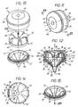
- this cable entry device 12 comprises, on the one hand, a base 13, which has a opening 14 suitable for a cable passage, and, on the other hand, a portion engagement 15, which extends annularly about the axis A of the opening 14 of the base 13.
- the opening 14 has a circular outline, and its diameter is considerably higher than that of the cable 11 to be engaged.
- the engagement portion 15 has, from a part, an outer wall 16, which extends forward, and by which it connects to the base 13, extending in practice like a cylinder right from the edge of the opening 14 of this base 13, and, on the other part, an inner wall 18, which, by turning back towards the rear the outer wall 16, is connected in U to the latter.
- the engagement portion 15 is split circularly in elastically deformable jaws 19, 19 ′, according to terms described in more detail later, and to this portion engagement 15, which is made of relatively rigid material, it is associated with a sealing member 20, which extends generally transversely relative to to the axis A of the opening 14 of the base 13, by obscuring at least partially this opening 14, and which is itself of relatively material flexible.
- relatively rigid material is meant, simply, here, a very generally, for the engagement portion 15, a material which is more rigid than the material of which the sealing member 20 is made.
- the organ seal 20 extends behind the engagement portion 15.
- the input device cable 12 comprises a rear part 22, which, integral with the base 13, is distinct from the latter and has a coaxial opening 23 of the opening 14 of this base 13, and the sealing member 20 intervenes at least partly between the engagement portion 15 and this rear part 22.
- the base 13 comprises a plate 21 and the rear part 22 forms a counter plate which extends substantially parallel to this plate 21.
- the plate 21 and the rear part 22 have an indeterminate extension, and one of them could also belong continuously to the wall to be crossed.
- the sealing member 20 also forms a separate part, and it intervenes between the plate 21 of the base 13 and the counterplate that forms the rear part 22.
- the engagement portion 15 is at least partly protruding forward on the base 13.
- the engagement portion 15 projects in its entirety towards the front on the base 13, and, more precisely, on the plate 21 that comprises it.
- the engagement portion 15 is of a integral with the base 13, forming by molding one and the same piece with it.
- the assembly is for example made in any of the materials following: PA (polyamide) 6.6, PC (polycarbonate), PVC (polychloride vinyl) rigid, ABS (acrylonitrine butadiene styrene), PP (polypropylene), or in a mixture of such materials, and, for example, in a mixture of PCs and ABS.
- PA polyamide
- PC polycarbonate
- PVC polychloride vinyl
- ABS acrylonitrine butadiene styrene
- PP polypropylene
- the base 13 and the engagement portion 15 form, jointly, in this embodiment, the front part of the device cable entry 12.
- the sealing member 20 is preferably made of elastically deformable material.
- the engagement portion 15 includes at least one jaw 19 of a first type, said here for simple convenience, jaw 19 long, of which the end envelops at rest a relatively narrow passage P, and at least a 19 'jaw of a second type, said here for convenience, short 19' jaw, the end of which envelops a relatively wide passage P 'at rest.
- the engagement portion 15 alternately comprises jaws 19 long and jaws 19 'short.
- All these jaws 19, 19 ′ have in plan a generally triangular contour, which converges towards the axis A of the opening 14 of the base 13, and which, for the definition of the corresponding passage P, P ', stops in an arc of circle away from this axis A.
- the passages P, P ' therefore have circular contours, but their diameters are smaller than that of this opening 14, the diameter of the passage P being itself smaller than the diameter of the passage P '.
- the jaws 19, 19 ' are almost adjacent to each other along their side edges, and the latter are substantially rectilinear.
- the jaws 19, 19 ' have, overall, a U-shaped profile.
- the jaws 19, 19 ' define the corresponding passage P, P ′ by an end section 25 which, preferentially, extends, at rest, substantially parallel to the axis A of the opening 14 of the base 13.
- the engagement portion 15 is split circularly in jaws 19, 19 ′ by slots 26, which, radially elongated, in a star, around the axis A of the opening 14 of the base 13, extend up to the base 13 and therefore affect both the inner wall 18 of this engagement portion 15, as the outer wall 16 thereof, running on the full height of the latter.
- this circumference C is the even for all the jaws 19, 19 '.
- a flange 27 extends to the connection of the outer wall 16 of the engagement portion 15 with the base 13, and the slots 26 extend to this flange 27.
- this flange 27 forms, peripherally, by its edge, a hexagon.
- the jaws 19, 19 'formed by the engagement wall 15 present, transversely, projecting on their outer surface, in the direction of the axis A of the opening 14 of the base 13, at least one notch 28.
- a notch 28 is provided, and, arranged at the root of the section end 25 of the jaws 19, 19 ′, it extends substantially perpendicularly to the axis A of the opening 14 of the base 13.
- the sealing member 20 locally belongs to a plate 30 sandwiched between the plate 21 of the base 13 and the rear part 22.
- the thickness E of this plate 30 is a multiple n of that e of the plate 21 of the base 13, FIG. 2.
- n is at least three.
- the sealing member 20 can, at least initially, be continuous, that is to say full, while being devoid of any drilling and even of any pre-drilling.
- the plate 30 to which this sealing member belongs 20 is made of foam rubber.
- the counterplate that forms the rear part 22 extends generally parallel to the plate 21 of the base 13.
- the rear part 22 has a web 31, which at least partially obscures its opening 23, and which is circularly fragmented into elastically deformable jaws 32.
- the web 31 of the rear part 22 has a thickness less than that of the backplate that the rear part 22 forms around it, this thickness itself being substantially equal to the thickness e of the plate 21 of the base 13.
- the web 31 of the rear part 22 is, externally, flush with the outer surface 33 of the counterplate that the rear part 22 forms around it, FIG. 6, and it intervenes at the bottom of a clearance 34 recessed on the inner surface 35 thereof.
- the jaws 32 of the rear part 22 have, in plan, a triangular contour, which goes in converging towards the axis A of the opening 14 of the base 13, and which stops in an arc away from this axis A.
- the jaws 32 formed by the web 31 of the rear part 22 are separated from each other by slots 36, elongated radially, in star, around the axis A of the opening 14 of the base 13.
- these jaws 32 go in tapering from their root to their free end.
- the jaws 32 of the part rear 22 are each respectively opposite the jaws 19, 19 'of the engagement portion 15.
- the rear part 22 is secured by crimping to the plate 21 of the base 13.
- this plate 21 carries, projecting, a plurality of crimping pads 37, which are distributed circularly around the axis A of the opening 14 of the base 13, and which, after crossing the member seal 20, pass through the rear part 22 using holes 38 provided in correspondence therefor.
- these crimping pads 37 have, transversely, a shoulder 39, to provide a stop for the rear part 22 and thus form spacer.
- the cable 11 is engaged from the front, along the arrow F1 of the Figures 7 and 8.
- figure 10A there is, by elasticity, a simple bending of the inner branch of the jaws 19, 19 ′ corresponding to the wall inner 18 of the engagement portion 15, by simple rotation relative to the outer wall 16 of this engagement portion 15, as shown schematically by arrows F2, F'2 in this figure 10A.
- the jaws 19, 19 ′ intervene elastically on the their entire length, both by bringing each other closer to one another two branches only by bending their outer branch.
- the sealing member 20 is forcibly traversed, and the jaws 32 of the rear part 22 are themselves driven back, following the arrows F4 in Figure 9.
- the mechanical retention of the cable 11 is ensured by friction, to essentially by the jaws 19, 19 ′ of the engagement portion 15, but, also, by the sealing member 20 and by the jaws 32 of the rear part 22.
- the jaws 19, 19 'of the portion engagement 15 intervene advantageously, by their notches 28, two different levels, namely, as shown schematically in Figure 9, at a level N relatively close to the plate 21 of the base 13 for the long jaws 19, and a level N 'relatively distant from this plate 21 for the short jaws 19'.
- the desired mechanical restraint is reinforced.
- the seal is provided by the seal member 20, this sealing member 20 enclosing the cable 11 continuously while around the periphery of this cable 11.
- the rear part 22 ensures advantageously maintaining this sealing member 20, confining this one, and avoiding it bursting during its perforation.
- the cable entry device 12 according to the invention can also advantageously be suitable for a whole range of cables 11 of diameters different.
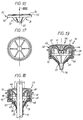
- the cable entry device 12 comprises a cover 40, which covers its engagement portion 15.
- This cap 40 has a side wall 41, by which it surrounds the outer wall 16 of the engagement portion 15, and a front wall 42, which extends in front of this engagement portion 15.
- the side wall 41 at least, is made of relatively rigid material, while the front wall 42 includes a knockout 44, which extends over at least part of its surface, and which itself is made of material relatively flexible.
- the side wall 41 is made of the same material as the engagement portion 15 and that the rear part 22, and the knockout 44 is made of elastomer.
- the front wall 42 comprises, at its periphery, in continuity with the side wall 41, a washer 45, which, in one piece with this side wall 41, forms a single and same room with this one.
- the knockout 44 therefore extends in this case only over a part of the surface of this front wall 42, in this case its central part.
- the side wall 41 of the cap 40 has, annularly, halfway up, projecting from its surface exterior, a rib 46, intended to intervene in the manner of a guard, for the support of the assembly on any wall 47 to be fitted, such as shown schematically in broken lines in Figure 10, then focusing either on the outer surface of this wall 47, as shown, either on its surface internal.
- the base 13 is reduced, as a corollary, to a ferrule 48, and the rear part 22 itself comprises a ferrule 50, which, by a shoulder 51, buttresses the base 13 thus constituted by such a ferrule 48.
- the cap 40 and the part rear 22 are secured to each other.
- the ferrule 50 of the rear part 22 comprises, around its shoulder 51, but recessed with respect thereto, a shoulder 52 on which the cap 40 carries by the edge of its wall lateral 41, and the cover 40 is secured to the rear part 22 at this level, by welding or the like, for example by ultrasonic welding.
- the cover 40 and the rear part 22 jointly delimit a enclosure 53 in which the engagement portion 15 and the base 13 of which it is united are imprisoned.
- the shell 48 of the base 13 carries by its outer surface against the inner surface of the side wall 41 of the cap 40.
- the engagement portion 15 can if desired carry by its zone top on the washer 45 of the front wall 42 of this cap 40.
- the slots 26 separating the jaws 19, 19 ′ are, at the level of the base 13, substantially enlarged, to facilitate the movement of these jaws 19, 19 '.
- the lateral edges of the inner branch of the jaws 19, 19 ′ are generally rounded.
- the sealing member 20 is molded to at least part of the rear part 22.
- the sealing member 20 extends on either side of the web 31 of the rear part 22, completely coating the jaws 32 of this web 31.
- the sealing member 20 has an opening 54 coaxial with the opening 14 of the base 13.
- the web 31 of the rear part 22 is generally frustoconical, with its concavity turned towards the portion of engagement 15.
- the sealing member 20 forms, beyond the free end of the jaws 32 of the web 31 of the rear part 22, a tube 55, which extends axially in the opposite direction to the engagement portion 15, and at the end of which intervenes the opening 54 of this sealing member 20.
- the tube 55 which thus forms the member seal 20 is frustoconical, with a taper less than that of the web 31 of the rear part 22.
- the half-angle at the top of the truncated cone formed by the tube 55 of the sealing member 20 is less than the half-angle at the top of the truncated cone formed by the web 31 of the rear part 22.
- the sealing member 20 is made of elastomer.
- the implementation, illustrated in FIG. 15, is also done from the same way as before, by force engagement of the cable 11 through the knockout 44 of the cap 40.
- a tablet can be pre-cut in the central area of this knockout 44.
- the cable entry device 12 according to the invention is suitable advantageously to cables 11 of different diameters.
- the cap 40 prevents, advantageously, in all cases, by its side wall 41, a spacing excessive jaws 19, 19 'of the engagement portion 15.
- the elastomer used for the constitution of the knockout 44 is translucent, even transparent, to allow a display of the internal volume of the following cable entry device 12 the invention.
- the rear part 22 advantageously, by the jaws 32 of its web 31, a frame for the sealing member 20, for the benefit of the mechanical strength of this one.
- the sealing member 20 advantageously facilitates the sliding of the cable 11 the along it, and ensures all the required tightness around this cable 11.
- a tool can be provided, in the form of a cannula, not shown, to facilitate possible removal of the cable 11.
- this plug 56 includes a plate 57, by which it comes to bear on the washer 45 of the front wall 42 of the cap 40, and, projecting from the internal surface of this plate 57, a boss 58, which is generally frustoconical, and by which it comes to enter the knockout 44, gradually pushing back radially.
- the plug 56 can be molded together with the rear part 22.
- the member sealing 20 extends only on the front face of the rear part 22.
- the sealing member 20 can just as well only extend over the back of the room rear 22.
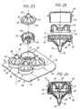
- the cable entry devices 12 are all identical between them, and these are cable entry devices of the type described with reference to Figures 11 to 21.
- the plate 21 ' which is common to them replaces the rib 46 of their cap 40.
- their cap 40 is in one piece with the plate 21 ' that they have in common with at least one other, forming one and the same piece with this 21 'plate.
- the various input devices of cable 12 thus associated are arranged in rows, possibly being in staggered from one row to another.
- the cable entry devices 12 of such an entity 59 may be of the type described with reference to FIGS. 1 to 9.
- the cable entry device 12 operates in isolation, at the like a cable gland.
- this cable entry device 12 is generally of the type of those described with reference to FIGS. 11 to 21.
- this rear part 22 comprises, beyond its ferrule 50, a sleeve 60, which is coaxial with this ferrule 50, and whose internal surface is tapped.
- the sealing member 20 completely obscures the opening 14 of the base 13, the tube 55 that this sealing member 20 being closed by a cover 62 at its end.
- the present invention is not limited to the forms of realization described and represented, but includes any variant and / or a combination of their various elements, in particular with regard to the number, and / or distribution, and / or configuration of the jaws that the engagement portion.
Landscapes
- Engineering & Computer Science (AREA)
- Architecture (AREA)
- Civil Engineering (AREA)
- Structural Engineering (AREA)
- Installation Of Indoor Wiring (AREA)
- Cable Accessories (AREA)
Description
Claims (39)
- Dispositif d'entrée de câble du genre comportant une embase (13), qui présente une ouverture (14) propre à un passage de câble, et une portion d'engagement (15), qui s'étend annulairement autour de l'axe (A) de l'ouverture (14) de l'embase (13), cette portion d'engagement (15) présentant une paroi extérieure (16), qui s'étend vers l'avant, et par laquelle elle se raccorde à l'embase (13), et une paroi intérieure (18), qui, en rebroussement vers l'arrière par rapport à la paroi extérieure (16), se raccorde en U à celle-ci, caractérisé en ce que, conjointement, la portion d'engagement (15) est fractionnée circulairement en mors (19, 19') élastiquement déformables par des fentes (26) qui s'étendent jusqu'à l'embase (13), en ce que, à leur raccordement à l'embase (13), les mors (19, 19') s'encastrent chacun dans celle-ci suivant une zone d'enracinement (Z) tangente à une circonférence (C) centrée sur l'axe de l'ouverture (14) de l'embase (13), et en ce que, à cette portion d'engagement (15), qui est en matériau relativement rigide, il est associé un organe d'étanchéité (20), qui s'étend globalement transversalement par rapport à l'axe (A) de l'ouverture (14) de l'embase (13), en occultant au moins partiellement cette ouverture (14), et qui est, lui, en matériau relativement souple.
- Dispositif d'entrée de câble suivant la revendication 1, caractérisé en ce que la paroi intérieure (18) de la portion d'engagement (15) comporte au moins un mors (19) d'un premier type, dit mors (19) long, dont l'extrémité enveloppe au repos un passage (P) relativement étroit, et au moins un mors (19') d'un deuxième type, dit mors (19') court, dont l'extrémité enveloppe au repos un passage (P') relativement large.
- Dispositif d'entrée de câble suivant la revendication 2, caractérisé en ce que la paroi intérieure (18) de la portion d'engagement (15) comporte en alternance des mors (19) longs et des mors (19') courts.
- Dispositif d'entrée de câble suivant l'une quelconque des revendications 1 à 3, caractérisé en ce que les mors (19, 19') que forme la paroi intérieure (18) de la portion d'engagement (15) présentent, transversalement, en saillie sur leur surface extérieure, en direction de l'axe (A) de l'ouverture (14) de l'embase (13), au moins un cran (28).
- Dispositif d'entrée de câble suivant l'une quelconque des revendications 1 à 4, caractérisé en ce que les mors (19, 19') que forme la paroi intérieure (18) de la portion d'engagement (15) ont, en plan, un contour triangulaire.
- Dispositif d'entrée de câble suivant l'une quelconque des revendications 1 à 5, caractérisé en ce que, au niveau de l'embase (13), les fentes (26) séparant les mors (19, 19') ont une largeur (L1) supérieure au tiers de la largeur (L2) de ces mors (19, 19') à ce même niveau.
- Dispositif d'entrée de câble suivant l'une quelconque des revendications 1 à 6, caractérisé en ce que l'organe d'étanchéité (20) est en matière élastiquement déformable.
- Dispositif d'entrée de câble suivant l'une quelconque des revendications 1 à 7, caractérisé en ce que l'organe d'étanchéité (20) est continu.
- Dispositif d'entrée de câble suivant l'une quelconque des revendications 1 à 8, caractérisé en ce que l'organe d'étanchéité (20) s'étend en arrière de la portion d'engagement (15).
- Dispositif d'entrée de câble suivant la revendication 9, caractérisé en ce qu'il comporte une pièce arrière (22), qui, solidaire de l'embase (13), est distincte de celle-ci et comporte une ouverture (23) coaxiale de l'ouverture (14) de cette embase (13).
- Dispositif d'entrée de câble suivant la revendication 10, caractérisé en ce que la pièce arrière (22) comporte un voile (31), qui occulte au moins partiellement son ouverture (23), et qui est fragmenté circulairement en mors (32) élastiquement déformables.
- Dispositif d'entrée de câble suivant l'une quelconque des revendications 10, 11, caractérisé en ce que l'organe d'étanchéité (20) intervient au moins pour partie entre la portion d'engagement (15) et la pièce arrière (22).
- Dispositif d'entrée de câble suivant l'une quelconque des revendications 10 à 12, caractérisé en ce que l'embase (13) comporte une platine (21), la pièce arrière (22) forme une contre-plaque qui s'étend sensiblement parallèlement à cette platine (21), et l'organe d'étanchéité (20) intervient entre cette platine (21) et la contre-plaque que forme la pièce arrière (22).
- Dispositif d'entrée de câble suivant la revendication 13, caractérisé en ce que le voile (31) de la pièce arrière (22) a une épaisseur inférieure à celle de la contre-plaque que la pièce arrière (22) forme autour de lui.
- Dispositif d'entrée de câble suivant l'une quelconque des revendications 13, 14, caractérisé en ce que l'organe d'étanchéité (20) appartient à une plaque (30) prise en sandwich entre la platine (21) de l'embase (13) et la pièce arrière (22).
- Dispositif d'entré de câble suivant la revendication 15, caractérisé en ce que l'épaisseur (E) de la plaque (30) à laquelle appartient l'organe d'étanchéité (20) est un multiple (n) de celle (e) de la platine (21) de l'embase (13).
- Dispositif d'entrée de câble suivant l'une quelconque des revendications 15, 16, caractérisé en ce que la plaque (30) à laquelle appartient l'organe d'étanchéité (20) est en caoutchouc mousse.
- Dispositif d'entrée de câble suivant l'une quelconque des revendications 1 à 17, caractérisé en ce que l'organe d'étanchéité (20) occulte entièrement l'ouverture (14) de l'embase (13).
- Dispositif d'entrée de câble suivant l'une quelconque des revendications 1 à 18, caractérisé en ce que, au raccordement de la paroi extérieure (16) de la portion d'engagement (15) avec l'embase (13), s'étend une collerette (27).
- Dispositif d'entrée de câble suivant l'une quelconque des revendications 10 à 12, caractérisé en ce que l'organe d'étanchéité (20) est surmoulé à une partie au moins de la pièce arrière (22).
- Dispositif d'entrée de câble suivant les revendications 11 et 20, prises conjointement, caractérisé en ce que l'organe d'étanchéité (20) est surmoulé au voile (31) de la pièce arrière (22).
- Dispositif d'entrée de câble suivant la revendication 21, caractérisé en ce que l'organe d'étanchéité (20) s'étend de part et d'autre du voile (31) de la pièce arrière (22), en enrobant totalement les mors (32) de ce voile (31).
- Dispositif d'entrée de câble suivant la revendication 21, caractérisé en ce que l'organe d'étanchéité (20) ne s'étend que sur la face avant de la pièce arrière (22).
- Dispositif d'entrée de câble suivant la revendication 21, caractérisé en ce que l'organe d'étanchéité (20) ne s'étend que sur la face arrière de la pièce arrière (22).
- Dispositif d'entrée de câble suivant l'une quelconque des revendications 20 à 24, caractérisé en ce que l'embase (13) se réduit à une virole (48), et la pièce arrière (22) comporte elle-même une virole (50) qui contrebute l'embase (13) ainsi constituée d'une telle virole (48).
- Dispositif d'entrée de câble suivant l'une quelconque des revendications 20 à 25, caractérisé en ce que l'organe d'étanchéité (20) comporte une ouverture (54) coaxiale de l'ouverture (14) de l'embase (13).
- Dispositif d'entrée de câble suivant l'une quelconque des revendications 20 à 26, caractérisé en ce que le voile (31) de la pièce arrière (22) est globalement tronconique, avec sa concavité tournée vers la portion d'engagement (15), et, au-delà de l'extrémité libre des mors (32) de ce voile (31), l'organe d'étanchéité (20) forme un tube (55) qui s'étend axialement en direction opposée à la portion d'engagement (15).
- Dispositif d'entrée de câble suivant la revendication 27, caractérisé en ce que le tube (55) que forme l'organe d'étanchéité (20) est tronconique, avec une conicité inférieure à celle du voile (31) de la pièce arrière (22).
- Dispositif d'entrée de câble suivant l'une quelconque des revendications 20 à 28, caractérisé en ce que l'organe d'étanchéité (20) est en élastomère.
- Dispositif d'entrée de câble suivant l'une quelconque des revendications 1 à 29, caractérisé en ce que la portion d'engagement (15) est d'un seul tenant avec l'embase (13).
- Dispositif d'entrée de câble suivant l'une quelconque des revendications 1 à 30, caractérisé en ce qu'il est associé à au moins un autre dispositif d'entrée de câble (12) de même type, en ayant en commun avec cet autre dispositif d'entrée de câble (12) une même platine (21, 21').
- Dispositif d'entrée de câble suivant l'une quelconque des revendications 1 à 30, caractérisé en ce qu'il intervient isolément, à la manière d'un presse-étoupe.
- Dispositif d'entrée de câble suivant l'une quelconque des revendications 1 à 32, caractérisé en ce que la portion d'engagement (15) fait au moins en partie saillie vers l'avant sur l'embase (13).
- Dispositif d'entrée de câble suivant l'une quelconque des revendications 1 à 33, caractérisé en ce qu'il comporte une coiffe (40) qui recouvre sa portion d'engagement (15).
- Dispositif d'entrée de câble suivant la revendication 34, caractérisé en ce que sa coiffe (40) comporte une paroi latérale (41), par laquelle elle entoure la paroi extérieure (16) de la portion d'engagement (15), et une paroi de façade (42), qui s'étend en avant de cette portion d'engagement (15), et sa paroi latérale (41), au moins, est en matériau relativement rigide, tandis que sa paroi de façade (42) comporte un opercule défonçable (44), qui s'étend sur une partie au moins de sa surface, et qui, lui, est en matériau relativement souple.
- Dispositif d'entrée de câble suivant les revendications 10 et 34, prises conjointement, caractérisé en ce que la coiffe (40) est solidarisée à la pièce arrière (22), et la coiffe (40) et la pièce arrière (22) délimitent conjointement une enceinte (53) dans laquelle la portion d'engagement (15) et l'embase (31) se trouvent emprisonnées.
- Dispositif d'entrée de câble suivant la revendication 36, caractérisé en ce que la coiffe (40) est solidarisée à la pièce arrière (22) par soudage ou analogue.
- Dispositif d'entrée de câble suivant les revendications 32 et 36, prises conjointement, caractérisé en ce que la coiffe (40) est solidarisée par vissage à la pièce arrière (22).
- Dispositif d'entrée de câble suivant les revendications 31 et 34, prises conjointement, caractérisé en ce que sa coiffe (40) est d'un seul tenant avec la platine (21') qu'il a en commun avec au moins un autre, en formant une seule et même pièce avec cette platine (21').
Applications Claiming Priority (5)
| Application Number | Priority Date | Filing Date | Title |
|---|---|---|---|
| FR9705915A FR2763436B1 (fr) | 1997-05-14 | 1997-05-14 | Dispositif d'entree de cable |
| FR9705915 | 1997-05-14 | ||
| FR9802323 | 1998-02-26 | ||
| FR9802323A FR2763437B1 (fr) | 1997-05-14 | 1998-02-26 | Dispositif d'entree de cable |
| PCT/FR1998/000936 WO1998052264A1 (fr) | 1997-05-14 | 1998-05-11 | Dispositif d'entree de cable |
Publications (2)
| Publication Number | Publication Date |
|---|---|
| EP0913016A1 EP0913016A1 (fr) | 1999-05-06 |
| EP0913016B1 true EP0913016B1 (fr) | 2003-08-06 |
Family
ID=26233532
Family Applications (1)
| Application Number | Title | Priority Date | Filing Date |
|---|---|---|---|
| EP98924414A Expired - Lifetime EP0913016B1 (fr) | 1997-05-14 | 1998-05-11 | Dispositif d'entree de cable |
Country Status (6)
| Country | Link |
|---|---|
| US (1) | US6194659B1 (fr) |
| EP (1) | EP0913016B1 (fr) |
| AU (1) | AU732326B2 (fr) |
| DE (1) | DE69816934T2 (fr) |
| FR (1) | FR2763437B1 (fr) |
| WO (1) | WO1998052264A1 (fr) |
Families Citing this family (24)
| Publication number | Priority date | Publication date | Assignee | Title |
|---|---|---|---|---|
| US6323433B1 (en) * | 1999-05-07 | 2001-11-27 | Pass & Seymour, Inc. | Connector grommet |
| US6430036B1 (en) | 2000-12-29 | 2002-08-06 | Progressive Dynamics | Electrical housing with non-integral cable outlet port member |
| FR2819116B1 (fr) * | 2000-12-29 | 2003-03-28 | Legrand Sa | Dispositif d'entree de cable |
| US6918787B2 (en) * | 2002-03-28 | 2005-07-19 | Fallon Egan | In-line connection cover |
| US6881901B2 (en) | 2003-08-21 | 2005-04-19 | Fallon Egan | Connection cover |
| US6953897B2 (en) * | 2003-08-21 | 2005-10-11 | International Business Machines Corporation | Device and method for clamping and grounding a cable |
| US7131088B2 (en) * | 2003-08-25 | 2006-10-31 | Legend Design Technology, Inc. | Reliability based characterization using bisection |
| US7387288B2 (en) * | 2003-12-05 | 2008-06-17 | The Lamson & Sessions Co. | Fitting for ENT tubing |
| SE527755C2 (sv) * | 2004-02-25 | 2006-05-30 | Paul Tapper | Kabelgenomföringsanordning för enkel installation |
| SE527756C2 (sv) * | 2004-02-25 | 2006-05-30 | Paul Tapper | En kärna för en kabelgenomföringsanordning |
| SE527958C2 (sv) * | 2004-02-25 | 2006-07-18 | Paul Tapper | Kabelgenomföring vilken är självjusterande till tjockleken av ett omgivande material |
| US20060145321A1 (en) * | 2004-12-30 | 2006-07-06 | Rohm And Haas Electronic Materials Llc | Microcomponent holder and method for manufacture thereof |
| ES2537091T3 (es) * | 2006-10-17 | 2015-06-02 | C.R. Bard, Inc. | Sistema de tratamiento de excrementos |
| US8777912B2 (en) | 2007-07-22 | 2014-07-15 | C. R. Bard, Inc. | Waste management system |
| US8192228B2 (en) * | 2008-02-26 | 2012-06-05 | SRI Hermatics Inc. | Electronic assembly including RF feedthrough connector and related methods |
| US20110001408A1 (en) * | 2009-07-06 | 2011-01-06 | Panduit Corp. | Network Cabinet Fitting System |
| US8507798B2 (en) * | 2009-08-21 | 2013-08-13 | Upsite Technologies, Inc. | Sealing grommet |
| US8791367B2 (en) * | 2009-10-14 | 2014-07-29 | Panduit Corp. | Network cabinet fitting system |
| USD653099S1 (en) | 2010-08-11 | 2012-01-31 | Upsite Technologies, Inc. | Grommet |
| USD719525S1 (en) * | 2014-05-19 | 2014-12-16 | Thomas DeCosta | Cable entry device for routing cables through a wall |
| US10840681B2 (en) | 2015-07-30 | 2020-11-17 | Federal-Mogul Powertrain Llc | Thermal sleeve with positioning member, assembly therewith and method of construction thereof |
| FR3052606B1 (fr) * | 2016-06-10 | 2020-08-14 | Legrand France | Embout d'entree de conducteurs electriques dans une boite electrique |
| EP3534472B1 (fr) * | 2018-03-01 | 2022-03-23 | Schneider Electric Industries SAS | Boîtier d'installation électrique |
| CN114137676A (zh) * | 2021-11-30 | 2022-03-04 | 汕头高新区奥星光通信设备有限公司 | 一种低收缩率中心管式带状光缆 |
Family Cites Families (10)
| Publication number | Priority date | Publication date | Assignee | Title |
|---|---|---|---|---|
| CH384654A (de) * | 1961-06-05 | 1964-11-30 | Grossauer Alfred | Vorrichtung zur Durchführung von elektrischen Leitungen durch eine Wand |
| GB1473294A (en) * | 1973-06-29 | 1977-05-11 | Fosroc Ag | Electrical junction box assembly |
| FR2402323A1 (fr) * | 1977-09-02 | 1979-03-30 | Sarel | Dispositif d'obturation d'une ouverture formee dans une paroi, en particulier d'un boitier d'interrupteur, d'une boite de derivation, formant un capuchon rapporte sur ladite paroi |
| DE3017383C2 (de) * | 1980-05-07 | 1982-05-06 | Dietrich 7778 Markdorf Grünau | Kabelverschraubung für Schaltschränke |
| US4490576A (en) * | 1981-08-10 | 1984-12-25 | Appleton Electric Co. | Connector for use with jacketed metal clad cable |
| DE3418978A1 (de) * | 1984-05-22 | 1985-11-28 | Hermann 7000 Stuttgart Holzmann | Kabelverschraubung |
| SE445408B (sv) * | 1984-09-26 | 1986-06-16 | Ake Bladh | Kabelgenomforing |
| US4738636A (en) * | 1987-04-13 | 1988-04-19 | Appleton Electric Co. | Strain relief connectors for flexible cord and cable |
| US5360945A (en) * | 1991-05-01 | 1994-11-01 | Raychem Corporation | Cable seal |
| US5696351A (en) * | 1995-03-10 | 1997-12-09 | Ericsson Raynet | Cable retention and sealing device |
-
1998
- 1998-02-26 FR FR9802323A patent/FR2763437B1/fr not_active Expired - Fee Related
- 1998-05-11 EP EP98924414A patent/EP0913016B1/fr not_active Expired - Lifetime
- 1998-05-11 WO PCT/FR1998/000936 patent/WO1998052264A1/fr not_active Ceased
- 1998-05-11 AU AU76621/98A patent/AU732326B2/en not_active Ceased
- 1998-05-11 DE DE69816934T patent/DE69816934T2/de not_active Expired - Fee Related
- 1998-05-11 US US09/214,513 patent/US6194659B1/en not_active Expired - Fee Related
Also Published As
| Publication number | Publication date |
|---|---|
| AU732326B2 (en) | 2001-04-12 |
| AU7662198A (en) | 1998-12-08 |
| DE69816934T2 (de) | 2004-07-15 |
| WO1998052264A1 (fr) | 1998-11-19 |
| DE69816934D1 (de) | 2003-09-11 |
| EP0913016A1 (fr) | 1999-05-06 |
| US6194659B1 (en) | 2001-02-27 |
| FR2763437B1 (fr) | 1999-08-13 |
| FR2763437A1 (fr) | 1998-11-20 |
Similar Documents
| Publication | Publication Date | Title |
|---|---|---|
| EP0913016A1 (fr) | Dispositif d'entree de cable | |
| CA2299664C (fr) | Dispositif de traversee etanche | |
| FR2762455A1 (fr) | Piece de raccordement etanche d'un tube a l'orifice d'une paroi | |
| EP0206854B1 (fr) | Procédé pour protéger les épissures de câbles et manchon pour la mise en oeuvre de ce procédé | |
| LU82815A1 (fr) | Manchon pour proteger l'epissure de cables electriques ou telephoniques | |
| EP0653825B1 (fr) | Dispositif de traversée étanche à membrane souple et opercule jetable | |
| EP1089411B1 (fr) | Dispositif destiné à être traversé de façon étanche par un corps cylindrique, boîte pour appareillage électrique et procédé l'utilisant | |
| EP1128512B1 (fr) | Embout de fermeture d'une goulotte de cheminement de câbles ou de conducteurs électriques | |
| FR2689331A1 (fr) | Embout à rapporter sur une paroi pour y constituer une sortie de câble. | |
| FR2819116A1 (fr) | Dispositif d'entree de cable | |
| FR2710790A1 (fr) | Dispositif de traversée étanche. | |
| EP0607083B1 (fr) | Accessoire de goulotte et goulotte équipée d'un tel accessoire | |
| EP0875975B1 (fr) | "Boíte d'encastrement pour cloison sèche à patte(s) de serrage initialement d'un seul tenant, notamment pour appareillage électrique" | |
| EP0991155B1 (fr) | Enveloppe, en particulier coffret, à fond présentant au moins un trou obturé par un bouchon, notamment pour matériel électrique | |
| EP1158634B1 (fr) | Embout pour goulotte de cheminement de câbles ou de conducteurs électriques | |
| EP1219881A1 (fr) | Elément à fixer en aveugle sur une paroi | |
| FR2763436A1 (fr) | Dispositif d'entree de cable | |
| FR2623024A1 (fr) | Connecteur auto-denudant pour conducteur electrique isole | |
| EP2237385B1 (fr) | Garniture de passe cable | |
| EP3506443B1 (fr) | Boîte électrique à profondeur variable | |
| FR2826091A1 (fr) | Piece d'etancheite pour la traversee d'un faisceau electrique a travers l'ouverture d'une paroi | |
| EP0721245A1 (fr) | Support d'appareillage à boîte semi-encastrée à travers un conduit, et son procédé de mise en oeuvre | |
| FR2780556A1 (fr) | Accessoire de branchement pour cable derive a raccorder a un cable principal, et connecteur de derivation equipe d'un tel accessoire de branchement | |
| FR2906089A1 (fr) | Capot pour fiche predeterminee de reseau d'information, ensemble et systeme le comportant | |
| FR2895583A1 (fr) | Dispositif d'enserrement etanche d'au moins un cable electrique |
Legal Events
| Date | Code | Title | Description |
|---|---|---|---|
| PUAI | Public reference made under article 153(3) epc to a published international application that has entered the european phase |
Free format text: ORIGINAL CODE: 0009012 |
|
| 17P | Request for examination filed |
Effective date: 19981230 |
|
| AK | Designated contracting states |
Kind code of ref document: A1 Designated state(s): BE DE FR GB IT NL |
|
| GRAH | Despatch of communication of intention to grant a patent |
Free format text: ORIGINAL CODE: EPIDOS IGRA |
|
| GRAH | Despatch of communication of intention to grant a patent |
Free format text: ORIGINAL CODE: EPIDOS IGRA |
|
| GRAA | (expected) grant |
Free format text: ORIGINAL CODE: 0009210 |
|
| AK | Designated contracting states |
Designated state(s): BE DE FR GB IT NL |
|
| REG | Reference to a national code |
Ref country code: GB Ref legal event code: FG4D Free format text: NOT ENGLISH |
|
| REF | Corresponds to: |
Ref document number: 69816934 Country of ref document: DE Date of ref document: 20030911 Kind code of ref document: P |
|
| GBT | Gb: translation of ep patent filed (gb section 77(6)(a)/1977) | ||
| NLR4 | Nl: receipt of corrected translation in the netherlands language at the initiative of the proprietor of the patent | ||
| PGFP | Annual fee paid to national office [announced via postgrant information from national office to epo] |
Ref country code: NL Payment date: 20040429 Year of fee payment: 7 |
|
| PGFP | Annual fee paid to national office [announced via postgrant information from national office to epo] |
Ref country code: GB Payment date: 20040504 Year of fee payment: 7 |
|
| PGFP | Annual fee paid to national office [announced via postgrant information from national office to epo] |
Ref country code: BE Payment date: 20040608 Year of fee payment: 7 |
|
| PLBE | No opposition filed within time limit |
Free format text: ORIGINAL CODE: 0009261 |
|
| STAA | Information on the status of an ep patent application or granted ep patent |
Free format text: STATUS: NO OPPOSITION FILED WITHIN TIME LIMIT |
|
| 26N | No opposition filed |
Effective date: 20040507 |
|
| PG25 | Lapsed in a contracting state [announced via postgrant information from national office to epo] |
Ref country code: GB Free format text: LAPSE BECAUSE OF NON-PAYMENT OF DUE FEES Effective date: 20050511 |
|
| PG25 | Lapsed in a contracting state [announced via postgrant information from national office to epo] |
Ref country code: BE Free format text: LAPSE BECAUSE OF NON-PAYMENT OF DUE FEES Effective date: 20050531 |
|
| BERE | Be: lapsed |
Owner name: *LEGRAND SNC Effective date: 20050531 Owner name: *LEGRAND Effective date: 20050531 |
|
| PG25 | Lapsed in a contracting state [announced via postgrant information from national office to epo] |
Ref country code: NL Free format text: LAPSE BECAUSE OF NON-PAYMENT OF DUE FEES Effective date: 20051201 |
|
| GBPC | Gb: european patent ceased through non-payment of renewal fee |
Effective date: 20050511 |
|
| NLV4 | Nl: lapsed or anulled due to non-payment of the annual fee |
Effective date: 20051201 |
|
| REG | Reference to a national code |
Ref country code: FR Ref legal event code: CD |
|
| BERE | Be: lapsed |
Owner name: *LEGRAND SNC Effective date: 20050531 Owner name: *LEGRAND Effective date: 20050531 |
|
| PGFP | Annual fee paid to national office [announced via postgrant information from national office to epo] |
Ref country code: DE Payment date: 20080514 Year of fee payment: 11 |
|
| PGFP | Annual fee paid to national office [announced via postgrant information from national office to epo] |
Ref country code: IT Payment date: 20080520 Year of fee payment: 11 |
|
| PGFP | Annual fee paid to national office [announced via postgrant information from national office to epo] |
Ref country code: FR Payment date: 20080331 Year of fee payment: 11 |
|
| REG | Reference to a national code |
Ref country code: FR Ref legal event code: ST Effective date: 20100129 |
|
| PG25 | Lapsed in a contracting state [announced via postgrant information from national office to epo] |
Ref country code: FR Free format text: LAPSE BECAUSE OF NON-PAYMENT OF DUE FEES Effective date: 20090602 |
|
| PG25 | Lapsed in a contracting state [announced via postgrant information from national office to epo] |
Ref country code: DE Free format text: LAPSE BECAUSE OF NON-PAYMENT OF DUE FEES Effective date: 20091201 |
|
| PG25 | Lapsed in a contracting state [announced via postgrant information from national office to epo] |
Ref country code: IT Free format text: LAPSE BECAUSE OF NON-PAYMENT OF DUE FEES Effective date: 20090511 |