EP0912871B2 - Einrichtung zum sichern einer schusswaffe sowie zum sichern und/oder aufbewahren von gegenständen - Google Patents
Einrichtung zum sichern einer schusswaffe sowie zum sichern und/oder aufbewahren von gegenständen Download PDFInfo
- Publication number
- EP0912871B2 EP0912871B2 EP97932639A EP97932639A EP0912871B2 EP 0912871 B2 EP0912871 B2 EP 0912871B2 EP 97932639 A EP97932639 A EP 97932639A EP 97932639 A EP97932639 A EP 97932639A EP 0912871 B2 EP0912871 B2 EP 0912871B2
- Authority
- EP
- European Patent Office
- Prior art keywords
- transmitter
- identification system
- identification
- locking
- locking mechanism
- Prior art date
- Legal status (The legal status is an assumption and is not a legal conclusion. Google has not performed a legal analysis and makes no representation as to the accuracy of the status listed.)
- Expired - Lifetime
Links
- 230000007246 mechanism Effects 0.000 claims description 31
- 230000009471 action Effects 0.000 claims description 10
- 230000008878 coupling Effects 0.000 claims description 7
- 238000010168 coupling process Methods 0.000 claims description 7
- 238000005859 coupling reaction Methods 0.000 claims description 7
- 229920003023 plastic Polymers 0.000 claims description 5
- 239000004033 plastic Substances 0.000 claims description 4
- 238000012545 processing Methods 0.000 claims description 4
- 238000012360 testing method Methods 0.000 claims description 4
- 230000003287 optical effect Effects 0.000 claims description 3
- 230000035945 sensitivity Effects 0.000 claims description 2
- 230000001815 facial effect Effects 0.000 claims 1
- 238000003032 molecular docking Methods 0.000 claims 1
- 238000010304 firing Methods 0.000 abstract description 20
- 238000009434 installation Methods 0.000 abstract 1
- 230000005540 biological transmission Effects 0.000 description 28
- 230000008901 benefit Effects 0.000 description 19
- 230000000694 effects Effects 0.000 description 11
- 230000006870 function Effects 0.000 description 9
- 238000012549 training Methods 0.000 description 9
- 238000010276 construction Methods 0.000 description 8
- 230000004913 activation Effects 0.000 description 7
- 238000005265 energy consumption Methods 0.000 description 7
- 230000009849 deactivation Effects 0.000 description 6
- 238000003780 insertion Methods 0.000 description 6
- 230000037431 insertion Effects 0.000 description 6
- 238000000034 method Methods 0.000 description 6
- 210000000707 wrist Anatomy 0.000 description 6
- 230000004888 barrier function Effects 0.000 description 5
- 238000013459 approach Methods 0.000 description 4
- 230000006835 compression Effects 0.000 description 4
- 238000007906 compression Methods 0.000 description 4
- 230000001276 controlling effect Effects 0.000 description 4
- 238000010586 diagram Methods 0.000 description 4
- 238000007726 management method Methods 0.000 description 4
- 230000002093 peripheral effect Effects 0.000 description 4
- 230000008569 process Effects 0.000 description 4
- 210000000689 upper leg Anatomy 0.000 description 4
- 238000012795 verification Methods 0.000 description 4
- 238000013475 authorization Methods 0.000 description 3
- 230000000903 blocking effect Effects 0.000 description 3
- 230000001419 dependent effect Effects 0.000 description 3
- 238000013461 design Methods 0.000 description 3
- 238000001514 detection method Methods 0.000 description 3
- 230000005684 electric field Effects 0.000 description 3
- 238000011156 evaluation Methods 0.000 description 3
- 238000012423 maintenance Methods 0.000 description 3
- 239000000463 material Substances 0.000 description 3
- 239000002184 metal Substances 0.000 description 3
- 230000011664 signaling Effects 0.000 description 3
- 230000002730 additional effect Effects 0.000 description 2
- 239000000969 carrier Substances 0.000 description 2
- 230000006378 damage Effects 0.000 description 2
- 230000007123 defense Effects 0.000 description 2
- 230000002950 deficient Effects 0.000 description 2
- 230000010354 integration Effects 0.000 description 2
- 238000012544 monitoring process Methods 0.000 description 2
- 210000000056 organ Anatomy 0.000 description 2
- 238000012552 review Methods 0.000 description 2
- 238000012546 transfer Methods 0.000 description 2
- 241001622623 Coeliadinae Species 0.000 description 1
- 229910000760 Hardened steel Inorganic materials 0.000 description 1
- 206010029216 Nervousness Diseases 0.000 description 1
- 229910000831 Steel Inorganic materials 0.000 description 1
- 206010044654 Trigger finger Diseases 0.000 description 1
- 238000005299 abrasion Methods 0.000 description 1
- 230000006978 adaptation Effects 0.000 description 1
- 230000000712 assembly Effects 0.000 description 1
- 238000000429 assembly Methods 0.000 description 1
- 230000002457 bidirectional effect Effects 0.000 description 1
- 230000008859 change Effects 0.000 description 1
- 238000005352 clarification Methods 0.000 description 1
- 238000004891 communication Methods 0.000 description 1
- 238000012790 confirmation Methods 0.000 description 1
- 238000011840 criminal investigation Methods 0.000 description 1
- 230000001627 detrimental effect Effects 0.000 description 1
- 238000011161 development Methods 0.000 description 1
- 230000018109 developmental process Effects 0.000 description 1
- 238000006073 displacement reaction Methods 0.000 description 1
- 238000004870 electrical engineering Methods 0.000 description 1
- 230000005672 electromagnetic field Effects 0.000 description 1
- 230000008030 elimination Effects 0.000 description 1
- 238000003379 elimination reaction Methods 0.000 description 1
- 230000007717 exclusion Effects 0.000 description 1
- 210000003746 feather Anatomy 0.000 description 1
- 239000003517 fume Substances 0.000 description 1
- 230000006266 hibernation Effects 0.000 description 1
- 230000009474 immediate action Effects 0.000 description 1
- 238000011835 investigation Methods 0.000 description 1
- 239000010985 leather Substances 0.000 description 1
- 230000005426 magnetic field effect Effects 0.000 description 1
- 230000007257 malfunction Effects 0.000 description 1
- 206010027175 memory impairment Diseases 0.000 description 1
- 238000012986 modification Methods 0.000 description 1
- 230000004048 modification Effects 0.000 description 1
- 230000003647 oxidation Effects 0.000 description 1
- 238000007254 oxidation reaction Methods 0.000 description 1
- 238000010422 painting Methods 0.000 description 1
- 230000035515 penetration Effects 0.000 description 1
- 239000013641 positive control Substances 0.000 description 1
- 230000036316 preload Effects 0.000 description 1
- 230000002028 premature Effects 0.000 description 1
- 230000001681 protective effect Effects 0.000 description 1
- 230000005855 radiation Effects 0.000 description 1
- 230000001105 regulatory effect Effects 0.000 description 1
- 230000008439 repair process Effects 0.000 description 1
- 230000004044 response Effects 0.000 description 1
- 238000006748 scratching Methods 0.000 description 1
- 230000002393 scratching effect Effects 0.000 description 1
- 230000007958 sleep Effects 0.000 description 1
- 239000010959 steel Substances 0.000 description 1
- 239000000725 suspension Substances 0.000 description 1
- 230000003313 weakening effect Effects 0.000 description 1
Images


Classifications
-
- F—MECHANICAL ENGINEERING; LIGHTING; HEATING; WEAPONS; BLASTING
- F41—WEAPONS
- F41A—FUNCTIONAL FEATURES OR DETAILS COMMON TO BOTH SMALLARMS AND ORDNANCE, e.g. CANNONS; MOUNTINGS FOR SMALLARMS OR ORDNANCE
- F41A17/00—Safety arrangements, e.g. safeties
- F41A17/06—Electric or electromechanical safeties
- F41A17/063—Electric or electromechanical safeties comprising a transponder
-
- F—MECHANICAL ENGINEERING; LIGHTING; HEATING; WEAPONS; BLASTING
- F41—WEAPONS
- F41C—SMALLARMS, e.g. PISTOLS, RIFLES; ACCESSORIES THEREFOR
- F41C33/00—Means for wearing or carrying smallarms
- F41C33/02—Holsters, i.e. cases for pistols having means for being carried or worn, e.g. at the belt or under the arm
- F41C33/029—Holsters, i.e. cases for pistols having means for being carried or worn, e.g. at the belt or under the arm combined with electronic devices, e.g. GPS
-
- F—MECHANICAL ENGINEERING; LIGHTING; HEATING; WEAPONS; BLASTING
- F41—WEAPONS
- F41C—SMALLARMS, e.g. PISTOLS, RIFLES; ACCESSORIES THEREFOR
- F41C33/00—Means for wearing or carrying smallarms
- F41C33/06—Containers for carrying smallarms, e.g. safety boxes, gun cases
Definitions
- the invention relates to a device for securing a firearm and a backup device and / or storing items such as this is described in the preambles of claims 1 and 2 is.
- US 5,461,812 A is a system for securing a firearm against unauthorized firing known.
- This weapon system comprises a assigned to an authorized user of the firearm Transmitter unit in the form of a finger ring and one of the Firearm assigned receiving unit for the of the transmission unit of the user can be emitted identification signals.
- this system comprises a programming device, with which the transmitting and receiving units programmed or coordinated can be. A firing with the Gun is only after successful identification an authorized user possible.
- These Identification takes place from the receiving unit in the firearm, by those of the transmitting unit emitted signals comprising an identification number evaluates.
- the transmitting unit of User assigned a switching device via which the transmitting unit depending on the respective Switch states with electrical energy from an energy source is supplied in the transmitting unit.
- the Switching device is designed such that the Sending unit only with electrical energy from the Power source is supplied in the form of a battery, when the transmitting unit is carried by a user and in addition a metallic object or the firearm is seized by this user, what for a metal detector is used.
- the receiving unit assigned an energy source in the weapon, which depending on a safety switch on the firearm the electrical components of the Receiver unit supplied with electrical energy.
- the disadvantage here is that the receiving unit as also the transmitting unit associated mechanical Switching devices for controlled power supply the transmitting unit and the receiving unit of course have a certain switching uncertainty.
- the proper switching function of the two switching devices can, for example, as a result of oxidation the switch contacts on the finger ring or the in Series switched switching contacts of the metal detector can not be guaranteed.
- From DE 44 46 020 A1 is a device known for controlled firing, in which between an authorized user and a weapon a transmitter-receiver system is constructed. Especially the authorized user is assigned a sender and on the weapon to be protected a receiver appropriate. The function of the weapon is only then released when a predeterminable spatial Maximum distance between the weapon and the authorized User is not exceeded and the weapon in an appropriate position to the authorized user is arranged.
- this system includes one Device about which the distance and distance the spatial position of the weapon to the authorized user is measured. Transmitter and receiver are included after activation of the system continuously in Contact and check while running the present Distance.
- Activation or activation of the Sender-receiver system can also by a a remote service or public authority or even by the authorized user himself over a PIN code, a bank card, a chip or a plug respectively.
- the disadvantage here is that the device for continuous monitoring of the distance between Transmitter and receiver or to monitor the situation Fail the weapon or determine incorrect readings can and then this to a malfunction of the weapon to lead. As a result, the authorized user is then but the wanted, often serving the self-protection Firearms use denied, causing such a System will find little appeal.
- From US 5,168,114 A is a safety device against unauthorized firearms use known which one in a bangle of a legitimate User arranged transmitting unit and a cooperating with this transmitting unit receiving unit has to be secured in the firearm.
- the transmitting unit is encoded for delivery Radio signals and trained by one of the user manually operated switch with a rechargeable Battery in the transmitter unit with electrical energy supplied, so then a corresponding radio signal can be submitted by the transmitter.
- the energy supply by the need operable switching means is the transmitting unit and the new receiving unit to be recoded or new to coordinate with each other. This coding takes place via a trained as an independent unit Coding device, via which the batteries of the Sending unit and the receiving unit recharged can be.
- the disadvantage is that in premature or unforeseen discharge of the battery in the Transmitting unit the firing is no longer possible and a new programming or voting the associated transmitting and / or receiving unit must be done via the coding device to ever again received a sharp or ready to shoot weapon to be able to.
- Another disadvantage of this battery-backed Sender unit is that the operational readiness of the system of the state of charge of the battery is dependent.
- US 5,062,232 A is another safety device to stop unauthorized Fee known. It is preferred the palm or the fingers of the authorized user Identification means in the manner of a permanent magnetic Associated with codes or a barcode. These Identification in the area of the user's palm or even on a glove is of a suitable one Reading unit in the region of the handle of the weapon scanned. If the read-in identity matches with a given identifier is the firing allows by using an electromagnet in the gun electrical energy from a battery applied becomes.
- the disadvantage here is that the identifier providing or the code generating permanent magnetic Medium or barcode after a long period of use inevitably subject to wear and tear therefore these identification means with increasing Service life increasingly difficult to read or even unusable become. The reliability of identification the authorized user is thus with consecutive Useful period as by abrasion on permanent magnetic means or by scratching of the barcode attached to the palm of the hand always lower, so that the authorized user the May be refused.
- This device includes one in the weapon arranged electromagnet, which is a mechanical Release or lock the firearm latch can.
- This electromagnet is dependent a switching device of a battery in the Firearm charged with electrical energy.
- the Energy supply of the electromagnet takes place only if a permanent magnet designed as a finger ring gets into the vicinity of the switching device and the connected in series in this switching device Switch contacts close the circuit and thereby the battery is the electromagnet with electrical energy applied.
- the switching device is through Magnetic field-dependent mechanical switching contacts formed, which only in the prevalence of a particular Switch field strength into the closed switching state.
- the disadvantage here is that the number clearly distinguishable Magnetic fields is severely limited and thereby the safety device with relatively low Effort can be bypassed.
- the present invention has the object underlying a security device for firearms to create a non-contact identification option creates and possibly also as a child safety device can be used. Furthermore intended a storage device with a safety device be created, which is a non-contact Identification creates and under Circumstances as a child safety device can be used.
- Another significant advantage is thereby given that batteryless and thus maintenance-free Transmitting and / or receiving units are formed, whereby a high level of operational safety is given and one constant readiness of the safety device ensures is.
- it is in the case of opening the opening a criminal not possible or expedient, because only if the authorized user prefers the Hand in the immediate area of the storage facility has, an opening of the locking device is possible. Even if a criminal Violent access to the storage facility he would be able to use the alarm system do not disable it and it persists the possibility of appropriate countermeasures and defensive measures hold true.
- a further advantage is training Claim 3, characterized by a unidirectional data transmission path is constructed and a transmitting unit clearly assigned receiving units a cost-effective Construction and an energy-optimized Enable operation of the safety device.
- a further embodiment according to claim 4 allows the construction of a bidirectional data transmission path, providing feedback enables the operating state of the safety device and, if appropriate, based on it Display and / or signaling devices the operating state of the safety device at any time can be monitored.
- An advantageous embodiment is further in the claim 6 described since the control or operation the safety device according to the invention or device about personal belongings of the authorized user, which is constantly available are not stored separately which may cause misplacement or loss of transmission and / or the user's receiving unit almost is excluded and furthermore a high security against misuse of the safety device, for example given by children.
- Due to the particular simple, fast and automatic handling for the activation or deactivation of the safety device is a surprise for attackers Defense possible because the attacker or criminals for a removal of the firearm a cumbersome Handling with code keys or keys.
- the rapid availability and operational readiness the firearm is also particularly for security guards or police officers of advantage.
- Furthermore is due to the particularly simple, fast and automatic handling for activation or deactivation the security device for a criminal Opening the storage device without cumbersome handling with code locks or Keys incomprehensible.
- an embodiment according to claim 8 of advantage since thus the distance between assigned Transmitting and / or receiving units for removal the firearm can be kept very low, whereby unintentional deactivation of the safety device is excluded. Furthermore the distance between assigned send and / or Receiving units for taking objects, for example, in the storage facility contained weapons, especially low be held, causing inadvertent deactivation the safety device excluded is.
- the small maximum distance between the transmitting and / or Receiving unit of the user and this assigned transmitting and / or receiving unit favors the use of a wireless or non-contact power transmission device.
- a further advantageous embodiment is in the claim 9, characterized as the energy consumption the identification device is reduced and nevertheless the verification of the authorized user without loss of security occurs when the review breaks keep it short.
- the advantageous embodiment according to claim 13 or 14 allows an individual adaptation of the Transmission distance or the transmission area, within which a deactivation of the locking devices can take place, whereby the different User requirements and e.g. the different dimensions of rifles or handguns can.
- Another advantage is training after Claim 15, since thus one for the respective application the safety device reliable data transmission can be chosen.
- a bypassing the safety device by unauthorized third parties is by training Claim 16 excluded because a copy or save the transmitted identification data an unauthorized third party due to transmission to transmission changing identification data is not effective.
- a further advantageous embodiment of the safety device is described in claim 18 This can be independent of transmission ranges or Reception sensitivities of the transmitting and / or receiving units the distance between the authorized user and the holding device or firearm determined and in the control sequence of the safety device be included.
- the distance can be between the authorized user and the hold and / or Storage device or the object determined and in the control sequence of the safety device be included, as appropriate particularly high functional and operational safety of Safety device is achieved.
- a particularly advantageous embodiment is characterized in claim 20, since thus only by resetting or returning the Firearm in the corresponding holding device of Charging, for example for the accumulators, can be initiated automatically. Furthermore can only by closing or equivalent Placing the holding and / or storage device the charging process, for example for the accumulators, be initiated automatically.
- the advantageous embodiment according to claim 40 allows with simple electrotechnical or mechanical means the activation or deactivation the locking device depending on the space or construction most suitable part the holding and / or storage device.
- a holding device for the safety device is in connection with the safety device a particularly rapid availability of handguns given higher defense or chances of overcoming criminals Persons exist.
- the advantage here is an education according to claim 22, since thus the removal of the firearm the holding device is checked and without additional activities the authorized user automatically Removal of the firearm is possible.
- a particularly simple, inexpensive and automatic locking or unlocking of the handgun with the holding device is according to claim 23 achievable.
- the embodiment according to claim 24 allows a particularly safe, heavy-duty lock the handgun with the help anyway at the Firearm of existing parts or training.
- the advantageous embodiment according to claim 25 allows automatic recording and locking the firearm through the holding device. Furthermore, This sensor can be used to detect the removal the firearm are used from the holding device and when recording the withdrawal times or removal time by the identification device in the investigation of criminal acts be useful or for the refutation or confirmation of a Serving alibis.
- an education according to claim 26 advantageous, since thus the handgun authorized User unhindered and quickly out of the one Unauthorized removal preventing holding device can be removed.
- Another advantage is a variant according to claim 27, characterized in that an unlimited mobile Safety device is created which ago especially for civil servants working in public service a high level of self-protection means. There one Disarming the security guard by unauthorized Third party is excluded, there is also a security gain for inside the security guard civilians.
- An education according to claim 30 allows building a safe and cost-effective Gun holster with the corresponding safety device.
- the advantage here is an education according to claim 41, since thus the opening of the holding and / or storage device is checked and without additional activities the authorized user an access or an access is possible in this.
- a particularly simple, inexpensive and automatic locking or unlocking is according to claim 42 achievable.
- the advantageous embodiment according to claim 43 allows automatic recording and locking of the article via the holding and / or storage device. Furthermore, this sensor can for detecting the removal of the object the holding and / or storage device used and recording the withdrawal times or the removal time by the identification device in the clarification of discrepancies be useful or used for billing purposes become.
- Another advantage is also a variant according to claim 44, characterized in that an unlimited mobile Facility is created, which is mainly for sale service a high level of working people Theft protection and ease of use means.
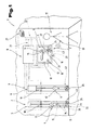
- Fig. 1 is a safety device 1 for several firearms 2 to 4 shown in holding devices 5, 6 and a trained as a holding device 7 Receiving box 8 are arranged.
- Each of the holding devices 5, 6 is about locking devices 9 or via a locking device 10 closed for the holding device 7.
- a release of these locking devices 9 or 10 is only by an identification device 11, for example, a microprocessor or a computing unit, via electrical and / or mechanical Release elements 12, 13 possible.
- release elements 12, 13 can either by appropriate circuit parts - driven about program parts of the identification device 11 - be formed and serve only, for example the power supply for the locking mechanism to interrupt or initiate so that the locking device 9, 10 opens by spring force, or it can be provided own drive elements be, which the locking device 9, 10 in a Move opening position, so that the removal of a the firearms 2 to 4 is possible.
- This mechanical / electrical Elements that the release elements 12, 13 can form, for example, by electrically operated Tie rod magnets, drive motors, linear drives or the like.
- Safety device 1 further includes the Firearms 2 and 4 associated Verriegeiungsvoruzeen 14, with which a firing tax also at one taken from the holding device 5 and 7 respectively Position can be prevented.
- These locking devices 14 or the associated release elements 15 are each in the firearms 2 and 4 installed so that they also possible from outside an experienced viewer are not recognizable.
- the locking devices 9, 10 and 14 associated release elements 12, 13 and 15 may be formed, it is in an advantageous Way possible that in the firearm 2, 4 arranged Release elements 15 own identification device 16 is assigned.
- connection between the identification device 11 and a user 17 is now wireless connected to the identification device 11 Transmitting and / or receiving units 18 and a user-carried transmitting and / or receiving unit 19. Is in or on the firearm 2, 4 itself an identification device 16 is arranged so can this another transmitting and / or receiving unit 20 for the exchange of identification data and / or Receiving electrical power.
- the permission a person checking identification device this is preferred with the locking devices 9, 10 for controlling the removal of the firearms 2, 4 line connected and with the locking device 14 for controlling the firing option in the firearm 2, 4 wirelessly, for example by radio, connected.
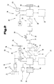
- Each of the identification devices 11 and 16 is either via a line 21 with a power supply system 22, for example accumulators 23, batteries or a public power grid wired or wireless over one alternating electric field 24 supplied from the outside with energy.
- the identification device 11 or 16 can thereby either incorporated in the holding device 5 to 7 or in one of them distanced, against unjustified Access protected area can be arranged.
- the identification device 11, 16 has a Mikrocontroler 25 and a transmitting device 26th to build up the alternating electric field 24 in the desired Distance range for the identification device 11, 16 associated transmitting and / or receiving unit 19 on.
- This alternating field 24 can be continuous be radiated. But it is also possible that the alternating field 24 in dependence of certain Conditions, for example when a person the room or the building or a protection zone enters, or only activated in certain time windows becomes. Such state determination is for example possible via infrared sensors 27. Of course It is also possible that the construction of the Alternating field 24 intermittently in short periods of time consecutively and / or depending on the Brightness occurs.
- a power supply in the transmitting and / or receiving unit 19 constructed so it can be a digital circuit or a computer 28 supplied with electrical energy become.
- a memory 29 a there stored identification code 30 read out and via an antenna 31 as schematically by a Wavy line indicated identification code 30 for Identification device 11, 16 are sent.
- the computer 28 with a corresponding test circuit, e.g. an A / D converter, is provided and an associated software program is deposited, which characteristics of the energy transmitting alternating field 24 or this Alternating field 24 superimposed, schematically by a Wavy line indicated detection signals 32 analyzed and compared with values stored in memory 29 become.
- a test circuit e.g. an A / D converter
- the comparison is positive, that is, the data is correct the alternating field 24 and the detection signal 32 correspond to the values stored in memory 29, only then will a dispatch of the identification code 30 performed via the antenna 31.
- An interception or interception and Abspeichem the transmitted identification code 30 is for unauthorized Third, preferred by the relatively low, maximum Transmission distance of the identification code 30 between the transmitting and / or receiving units 18, 19, 20, almost impossible.
- the encryption and / or decryption units 33, 34 are preferably software-based through the Mikrocontroler 25 or the computer 28 formed.
- the identification code 30 is thereby encrypted with encryption keys prior to transmission and at the respective remote station by means of decrypted the same encryption key, which the original identification code 30 again is present.
- the encryption codes of the sending office or the decryption codes of the remote station doing different from send to send. This creates for a listener the Impression of a random code transmission, causing the Recording the transmitted data is pointless.
- variable encryption or decryption of the Identification codes 30 by the encryption and / or Decryption units 33, 34 can thereby over the transmitting and / or receiving units 18, 19, 20 associated encryption or decryption algorithms will be realized. It is the same possible, the encryption or decryption codes in tabular form in memory units of the microcontroller 25 and the computer 28 to deposit and after every successful communication setup between the transmitting and / or receiving units 18, 19, 20 to increment the table pointers to an offset the table pointer positions of the send and / or Reception units 18, 19, 20 exclude.
- Such a "Handshake" to check the correct, complete data exchange between the sending and / or Receiving units 18, 19, 20 is also when using an encryption algorithm possible, by the same number of cycles in the Verschtüsurtgs- or decryption routine and thus a matching encryption and decryption to maintain or guarantee.
- Such an encrypted or unencrypted Signal is now, for example, from the antenna 31 of the transmitting and / or receiving unit 18 and / or 20 of the identification device 11, 16 received, if necessary, decrypted and sent to a circuit or to the Mikrocontroler 25 of the identification device 11, 16 forwarded for evaluation.
- the identification device 11, 16 is also a storage unit 35 in which preferably several Identification codes 36 may be stored, which a release of the release element 12, 13 or 15 cause assigned.
- Identification codes 36 may be stored, which a release of the release element 12, 13 or 15 cause assigned.
- the electromagnetic Alternating field 24 for energy transfer so weak is that the transmitted energy to the operation of the computer 28 of the transmitting and / or receiving unit 19 at User 17 is only sufficient when the two Transmitting and / or receiving units 18, 19 or 19, 20 in the desired, predeterminable distance or in the predeterminable range of distances.
- the distance or the distance range is preferred via appropriate input devices or Switch adjustable or predeterminable.
- the Safety device to individual requirements be adapted to the user and, for example also due to different forms of Firearms, for example, whether they are rifles or handguns, the different ones Dimensions and holding positions of the same invoice be worn.
- the Storage means different Dimensions, operating positions or access points Be taken into account.
- Distance measuring devices 37 the transmitting and / or Receiving units 18, 19, 20 assign or circuitry Devices or drainage technical Provide operations that are due to the received or emitted radiation whose strength, frequency response, Interference or the like the distance between them Transmitting and / or receiving units 18, 19 and 19,20 constantly or periodically determine.
- a preferred Possibility to determine the distance is e.g. the Monitoring the duration of the signals by reference the clock pulses of the computer 28 and the Mikrocontrolers 25 or due to the determination of the time differences starting from simultaneously initiated Clock pulses or of example in tabular form in the computer 28 or in Mikrocontroler 25 or in corresponding Storage units stored runtime values for the transmission and return of signals between the transmitting and / or receiving units 18, 19 and 19, 20.
- distance measuring devices 37 used which ultrasonic signals send out and based on the delay of the back transmitted ultrasonic signal the distance to the remote station or to the reflection surface via physical Calculate formulas.
- the alternating field 24 can be such Have intensity that a sufficient energy supply the transmitting and / or receiving unit 19 at the user 17 outside the Entfemungs Schemees is given if this transmitting and / or receiving unit 19 does not have its own power supply and is designed in the manner of a transponder 38.
- Such an embodiment is therefore advantageous because the space required for the computer 28 and the necessary electronic components at the user 17 can be kept extremely small and their integration - As excerpts in Fig. 4 can be seen - in from User 17 worn clothing and / or Jewelery 39, such as a ring, a Watch strap 40, a watch case 41, a belt buckle or the like., Is possible.
- transponders in particular the transponder 38, also has the advantage that this principle only for use at low Distances to the remote site are suitable, so that a Foreign influence but also a foreign surveillance or reading the data during data transmission, if at all, very difficult is.
- the identification code 30, 36 exclude by means of small or smallest distances, it may prove necessary - before In particular, if several firearms 2 to 4 through a central identification device 11 is monitored - that in the range of each firearm 2 to 4 a own transmitting and / or receiving unit 18 is arranged is, so that the firearm 2 to 4 actually only removed can be when the user's hand 17 in close proximity to the respective firearm 2 to 4 or to the respective holding device 5 to 7 located.
- the identification device 11 While now in the preceding the function the identification device 11 mostly based on the Function of the release elements 12, 13 for the Firearms 2 to 4 for those in the fixtures 5-7 held guns 2 to 4 described It should be noted that a similar or similar Function or design of the identification device 11 also for the identification devices 16 used assigned to the firearm 2 and 4, respectively is.
- the power supply system is preferred 22, in particular the accumulator 23, for operating the identification device 16 in the Gun 2 or 4 installed and it is alike the transmitting and / or receiving unit 19 of the user 17 suitable for the release element 15 of Locking device 14, for example for the Close the firearm 2 or 4, release or to lock.
- This locking device 14 must but not on the closure act, but can also act on a trigger 42 and this trigger release or block the firing.
- transponder 38 and the power supply for the identification device 16 by the user 17 to let go or initiate.
- two transponders 38 work, both in the field of identification device 11 as well as in the field of Firearm 2 and 4 and in the rooms in which such weapons are kept and on the body of the User 17, a separate transmitter to arrange for the alternating field 24, so that always, if the corresponding transponder 38 in the area This alternating field 24 are an actuation the release elements 12, 13 and 15 is possible.
- a constantly operational Identification device 16 against unauthorized To ensure firing are preferred to the Holding devices 5, 6 and 7, respectively, loaders 43 arranged, which the accumulators 23 under utilization full capacity or full capacity Charge state received.
- the charging devices 43 can be either with the accumulators 23 in electrical contact or wirelessly over the electromagnetic alternating field 24 with electrical energy be supplied.
- the electrical supply takes place thereby automatically by the holding devices 5, 7 held firearms 2, 4.
- the entire duration of use which depending on the capacity of the accumulators 23 and depending on the power consumption of the identification device 16 days may be available.
- there is no need for additional manual maintenance such as. the manual contact of the identification device 16 with the charger 43, since the Charging automatically by resetting the Firearm 2, 4 in the respective holding device 5, 7th is initiated.
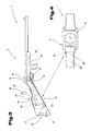
- Fig. 3 shows an enlarged view of Firearm 2 according to Fig. 1, wherein already vorvor obtainedd already Parts described using the same reference numerals become.
- This firearm 2 forms a handgun and is shown in rifle shape. Of course is the following description accordingly also adapts for the handgun shown in Fig. 1 valid.
- the identification device 16 is from invisible on the outside in a slot-shaped recess 44 arranged in the rifle piston 45.
- existing accumulators 23 are preferably in the recess 44 in the support region 46 of the rifle piston 45 invisible arranged and over the mostly elastic buffer member 47 of the rifle piston 45 accessible.
- the accumulators 23 in the Rifle shaft 48 to integrate, reducing the balance the firearm 2 or not, hardly changed becomes.
- the printed circuit board of the arithmetic unit of the identification device 16, in particular formed by one Microcontroller 25 with all peripheral modules, is preferably also in the recess 44th the rifle piston 45 is arranged.
- the release element 15 can be moved by the tie rod magnet and thus the Enable or disable fume 42. To high blocking forces at the same time low unlocking forces and thus to achieve low electrical energy consumption, It is possible to use any of the prior art known pawls and / or latch mechanisms use.
- the arrangement of the transmitting and / or receiving unit 20 be different, by maximum transmission distances of a few Centimeters to be able to create an application the firearm 2 against the authorized user 17 already because of the size dimensions of the Gun 2 is excluded.
- the transmitting and / or receiving unit 19 in or on a wristwatch which is usually on left wrist are different Arrangement options advantageous, which a short Distance between the assigned send and / or Reception units 19, 20 allow.
- the transmitting and / or receiving unit 20 preferably in a tapered region 50 of Rifle butt 45 in the weft direction immediately before arranged the trigger 42, since this area 50 at Sighting the target and using the firearm 2 is enclosed by the palm and thus a comparatively short distance is present.
- the user 17 uses a finger of the right hand for the operation of the trigger 42, so is the left hand of the user 17 with the send and / or Receiving unit 19 for supporting the rifle stock 48.
- the transmission and / or receiving unit 20 for achieving a the smallest possible distance - as in dashed lines shown - in the rifle stock 48 of the firearm 2.
- Fig. 4 are various arrangement options the transmitting and / or receiving unit 19 for the embodiment of a wristwatch shown.
- switching elements 51 on the Wristwatch be arranged, which the process or the state of the transmitting and / or receiving unit 19 or the entire safety device 1 influence can.
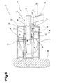
- Fig. 5 is one in comparison to Fig. 1 other Embodiment variant of the holding device 7 for the Firearm 4, in particular formed by a handgun 52, shown.
- the handgun 52 held by the holding device 7 and at least one holding part 54, in particular one Handle 55, freely accessible.
- This holding device 7 is on a wall 56th fixed or walled in the wall 56 such that a front plate 57 of the holding device 7 with the wall 56 planar closes and only one opening 58th for the barrel 53 of the firearm 4 can be seen.
- a receptacle 59 of the holding device 7 is thereby formed such that the barrel 53 received and at least partially enclosed can.
- a removal of the firearm 4 from the holding device 7 is depending on the position of a locking device 60, 61, 62 allows or prevents.
- Each of the locking devices exemplified 60 to 62 can be alone or in combination with at least one further locking device 60 to 62 the removal of the firearm 4 allow or prevent from the holding device 7, whereby the locking devices 60 to 62 can be used optionally.
- the locking devices 60, 61 are in Area arranged around the receptacle 59 and via electromagnetic Drive elements 63, 64 may lock pin 65, 66 in or out of the interior of the tubular Recording 59 to be moved.
- Locking pin 65 for example, a target device 67th behind in the mouth area of the barrel 53 and such a withdrawal of the firearm 4 from the holding device 7 prevent.
- the Locking pin 69 the area between the trigger 42nd and assign the handle 55 to the handgun 52, on the one hand the removal of the handgun 52 is regulated and on the other hand, the locking pin 69 in Trap of a handgun 52 without checking the entitled firing as a mechanical lock against actuation of the trigger 42 at salary Handgun 52 is used.
- Identification device 11 forwarded and after successful, positive identity verification will be from the identification device 11 the locking devices 60 to 62 subjected to electrical energy. Thereby be the locking pins 65, 66, 69 in the retracted Position offset and for the authorized user is a removal of the firearm 4 from the holding device 7 possible.
- a firearm 4 in the fixture 7 is held or removed from the holding device 7 is, by any, preferably in the field the opening 58, arranged sensors 72 are determined and the identification device 11 as control information serve.
- the locking pins 65, 66, 69 in the retracted position be offset, creating an unhindered insertion of the barrel 53 in the receptacle 59 allows becomes.
- the fully inserted firearm 4 is subsequently by means of at least one of the locking devices 60 to 62 locked in the respective position.
- Including the sensor 72 which for example by optical light barriers, Hall sensors, Limit switch or other from the Prior art known donors may be formed, is also the construction of a time recording system with Logging the removal of the firearm 4 possible.
- the sensor 72 with the identification device 11 line connected and a timer device the same, for example, formed by a the microcontroller 25 associated timer module, provides the microcontroller 25 with the time and / or date information to disposal.
- the thus determinable Withdrawal times, removal periods and withdrawal days the firearm 4 from the holding device 7 are stored by the identification device 11 and
- an output device such as. a display, visualized or via a Printer can be output in paper form.
- the holding device 7 is compared to the holder or storage the firearm 4 in a receiving box. 8 a much faster availability of the firearm 4 possible.
- the ready to handle, against unauthorized removal secured firearm 4 is particularly in the case of threat for the authorized user of significant Advantage.
- the automatic unlocking of the Firearm 2 of the holding device 7, as shown in FIG. 5, also increases the surprise effect for the attacker, giving extra benefits to the defending ones Users arise.
- By eliminating the manual unlocking and locking the gun 2 is besides the high level of safety, especially towards children, a particularly comfortable holding device 7 for reached the firearm 4.
- the holding device 7 of FIG. 5 also under a desk, near the bed, in a vehicle or other, if necessary, a quick one Availability of the firearm requiring bodies at the same time high abuse security and unhindered Accessibility be arranged.
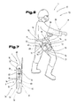
- Fig. 6 the user 17 of the safety device 1 in the form of a security officer 73 or policemen shown. This is wearing a holster 74 with the handgun 52 inserted therein.
- the holster 74 for receiving the Handgun 52 is usually made of hard plastic formed and at one around the body of the security guard 73 looped strap 75 attached. Possibly is opposite to the support belt 75 Front end region of the holster 74 a Connecting device 76, in particular in the form of a around the thigh of the security officer 73 looped band 77, arranged.
- the Holster74 with the body of the security guard 73 tear-proof without impairing the wearing comfort connected.
- the handgun 52 in the held by the holster 74 position, so is at least the barrel 53 and the trigger 42 substantially from the receptacle 78 forming side walls of the holster 74 enclosed.
- the holding part 54 the handgun 52 is not covered or not surrounded by parts of the pistol holster 74 and thus always at hand.
- the identification device 11 including all required peripheral modules arranged.
- the transmitting and / or receiving unit 18 or the transmitting and / or receiving coil 80 can be camouflaged as a fastening rivet between executed the gun holster 74 and the support belt 75 be, whereby the presence of the invention Safety device 1 not visible is.
- the locking device 62 is preferred in the area of the trigger 42 of the handgun 52 in the receptacle 78 of the holster 74 and preferably with the identification device 11 conductively connected.
- the locking pin 69 is preferably a receiving socket for the stable storage of the end area the locking pin 69 when taking the locking position assigned.
- the receiving socket or mounting hole opposite side wall of the holster 74 is the one movement of the locking pin 69 enabling drive element 71 on the preferred made of hard plastic sidewall of the Holster fastened or positively with this connected.
- the mounted on both Stimend Schemeen Lock pin 69 and the hard-shell holster 74 thus ensure a high tear-resistance or tear resistance of the handgun 52 the holster 74.
- the safe collection state of the handgun 52 can only after positive identification of the authorized security officer 73 become.
- the security officer 73 means assigned to the transmitting and / or receiving unit 19 Identify identification code 30.
- the transmission and / or receiving unit 19 may be for this purpose camouflaged as a wristwatch, preferably on that wrist attached, which the firing or removal hand of security guard 73.
- Security Officer 73 takes hold 55 the handgun 52, so it inevitably comes as a result to reach or fall below the preferably pre-settable distance range between the transmitting and / or receiving unit 19 and the transmitting and / or receiving unit 18. Thereafter, from the identification device 11, the evaluation of received identification codes 30 made and after a positive identity check this controls the Locking device 62, whereby the locking pin 69 is placed in the unlocked position and a Immediate removal of the handgun 52 possible is. At the same time, after positive identification Security Guard 73 through the identification device 16 lifted the weft tax safeguard become, thereby for the legitimate security officer 73 an immediate firing is possible.
- the distance between the transmission and / or or receiving unit 19 and the transmitting and / or Receiving unit 18 is preferably set such that with drooping or strolling arms Security Guard 73, so when the Transmitting and / or receiving unit 19 in the thigh area There is no release of the handgun 52 takes place.
- the security guard seizes 73 the handgun 52, so is the send and / or Receiving unit 19 with the identification code 30 in the hip area, so in the immediate distance to Transmitting and / or receiving unit 18 on the carrying belt 75, whereby it is particularly advantageous, a corresponding Distance of a few centimeters as the default value for the identification device 11, to effect a repeal of the removal safeguard to be able to.
- Fig. 7 is another embodiment of the holster 74 with the safety device 1 shown in side view, with vorvor obtainedd already mentioned parts the same reference numerals used become.
- the handgun 52 In the state held by the holster 74 the handgun 52 is the barrel 53 of the same also in the recording 78 of the holster 74. However, here is the handle 55 of the handgun 52 of a closing device 81, in particular formed by a closure flap 82, coverable, thereby seizing and removing the Gun 52 allows or prevents.
- This is the closure device 81 with one end 83 permanently connected to a side wall of the holster 74 or articulated.
- Another end 84 of the Closing device 81 is via a coupling device 85 with another side wall of the holster 74 connected. This coupling device 85 gets through this side wall of the holster 74 protruding and from the closing device 81 protruding locking mandrel 86 is formed.
- the closing device 81 or, the closure bib 82 is in particular of little dimensional stability Materials such as e.g. Leather, formed.
- the transmitting and / or receiving unit 18 is preferably in the area of the handle 55 on the holster 74 arranged and arranged with the in the receptacle 78 Identification device 11 preferably conductively connected.
- sensors or switch may be arranged, which with the identification device 11 are connected and information with regard to drawn or inserted Handgun 52 deliver, creating an unhindered Resuming and locking the handgun 52 are automated after pulling them can.
- the safety device 1 it is also possible to use the safety device 1 to assign an alarm and / or signaling device, which on reception of the system unknown and thus the removal of firearms refusing and / or not permitting the firing Identification codes 30 is activated.
- the safety device 1 may prove advantageous the safety device 1, a timing device to assign, with which the safety device 1 during the service, e.g. a security officer 73 is active and at the other times, e.g. during the night hours to the exclusion of Misuse e.g. by children a release of the safety device 1 is prevented.
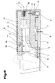
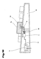
- FIG. 8 is another embodiment of a Holding device 7 partially in phantom for a firearm 4, in particular a handgun 52, shown.
- This holding device 7 comprises a receptacle 59, for example, a cut-resistant, high-resistance and hard material, for example hardened steel.
- a longitudinal guide 87 arranged for the barrel 53 of the firearm 4.
- the longitudinal guide 87 may have a cross-sectional dimension perpendicular to their length, which is approximately corresponds to the cross-sectional circumference of the barrel 53, or be arranged so that the barrel 53 something from the Longitudinal guide 87 protrudes the amount.
- the length of the Longitudinal guide 87 may be sized so that the handle 55 of the firearm 4 for the user 17 to capture the firearm 4 is freely accessible.
- the locking device 62 for fixing and holding the Firearm 4 in the receptacle 59 comprises one in one Longitudinal slot 88 arranged guide carriage 89, wherein the longitudinal slot 88 parallel to the longitudinal guide 87, but at a corresponding distance from the side, is arranged in the guide carriage 89.
- Pivoting axis 90 On the guide carriage 89 is a Pivoting axis 90 arranged on which pivot arms 91 of a locking bracket 92 of the holding device 7 are mounted rotatably or pivotally.
- a longitudinal distance 95 between the Swivel arms 91 corresponding distance are in the from the firearm 4 averted side cheek 96th the receptacle 59 openings 97 arranged.
- the Cross-sectional dimensions of these openings 97 are as well as their depth so dimensioned that in the area of this Openings 97, the pivot arms 91 to the Swivel axes 90 from the in full lines in the in dashed lines shown position accordingly an arrow 98 can be pivoted.
- a width 99 of the locking bracket 92 is so that it protrudes so far beyond the firearm 4, that this upwards not from the longitudinal guide 87 can be removed.
- the locking bracket 92 at its from the longitudinal guide 87 turned away towards the end Swivel axes 90 directed projection, the so far down that it is in the longitudinal guide 87th inserted firearm 4 whose from the longitudinal guide 87 averted front end 100 at least partially surmounted or overlapped.
- Reaches the holding force of the drive element 71 not to the firearm 4 and the locking bracket 92 in the closed position even at high Force application to the handle 55 of the firearm 4, can be an additional electrically operated, for example electromechanically designed, locking device or provided a locking element be, with which, for example, the guide carriage 89 in the longitudinal slot 88 in its closed position is fixed.
- electromechanical lock can retractable pins, notches, self-locking screw drive or for example Locking pin 69, as shown schematically in Figure 8 shown in accordance with the comments on Fig. 5th can be used.
- the safety device according to the invention 1 is in accordance with the above explanations in can be used in a wide variety of operating modes. Hereinafter should be single advantageous procedures for the identification and operation of the safety device 1 are listed:
- Security device 1 possible, a multiple identification for example, run in such a way that when entering a room, the face shape, a hand contour or a fingerprint or similar to the coarse identification is used and only if this identification is positive and upon delivery of the correct identification code 30 the identification device 11, 16, one of Firearms 2 to 4 is released.
- the operation of the locking device 9, 10; 14; 60; 61; 62 in different Way possible. This is the case, for example, when sharing the locking device 9, 10; 14; 60; 61; 62 possible, only a very short time for removal provide the firearm 2 to 4 and that after this period, the firearm 2 to 4 is immediately locked again. But it is also possible that over the period of time over which the user 17, in the field of identification device 11, 16 is located the locking device 9, 10; 14; 60; 61; 62 open continuously remains.
- the Identification before release of firearm 2 to 4 in more than two stages, so that different Criteria must be met before the release via the identification code 30 in accordance great approach of the user 17 to the firearm 2 to 4 takes place.
- another unlocking member 101 e.g. a switching element or a sensor surface with the identification device 11 is connected and only if this additional unlocking member 101 during a positive Identification via the identification device 11 due to a small distance between the Transmitting and / or receiving units 18 to 20 given is, the locking device 9, 10, 14, 60 to 62 released becomes.
- Such unlocking member 101 which, for example, by a push button switch a light barrier or the like may be formed can, causes the release by the locking devices 9, 10, 14, 60 to 62 even if for example, a handshake more often in a position to the firearm 2 to 4, the one release due to the removal of the send and / or Reception units 18 to 20 allow would only then be released if from the authorized user at the same time this release organ 101 is operated.
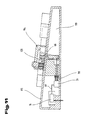
- Fig. 9 is a variant of the holding device 7 for a firearm 4, e.g. a handgun 52, shown.
- This holding device 7 is made turn from a recording 59 of hard, resistant Material, for example, in a Wall walled or freestanding on this or one Furniture or in a vehicle or the like. Attached can be.
- a recess 102 arranged, in which a carriage 103 in the direction a longitudinal axis 104 of the recess 102 below the effect of a compression spring 105 slidably mounted is.
- this carriage 103 is a longitudinal guide 87 arranged for the barrel of the firearm 4.
- the Longitudinal guide 87 may have a cross-sectional dimension perpendicular to its length, which is the cross-sectional perimeter of the barrel 53 corresponds.
- the handle 55 the firearm 4 is e.g. in a groove-shaped receptacle 106 held against twisting.
- a recording slot 107 of the carriage 103 is a locking bar 108 about a transversely to the longitudinal axis 104 aligned Swivel axis 109 from the drawn in full lines Locking position in a dashed line drawn, highly pivoted release position for the firearm 4 pivoted.
- the carriage 103 In the position shown in full lines of the Carriage 103, in which the compression spring 105 is compressed is and the firearm 4 with the handle 55 in the groove-shaped receptacle 106 and the locking bar 108 against unauthorized removal is the carriage 103 via the locking device 62nd secured within the recess 102 in the receptacle 59 held.
- the locking device 62 is formed by a locking pin 66, which is against the effect a spring 110 from the extended
- the Slide 103 fixing locking position means a drive element 71, for example by means of a Electromagnet in an outside of the recess 102 located opening position, moves can be.
- the control of the drive element takes place for example, via the identification device 11, which are incorporated in the receptacle 59 inside can and via a line 111, for example, with a Power supply or another data processing device can be connected.
- an accidental Release of the firearm 4 is done, in addition in the area of the handle 55 of the firearm. 4 facing holding part with the receptacle 106 a Entriegelungsorgan 101, for example, a push-button switch be arranged, so that the locking device 62 only by the movement of the locking pin 66 with the drive element 71 in its unlocked position is adjusted if to the match the identification code in the identification device 11 also this pushbutton or switch or the unlocking member 101, which also by non-contact working elements such as light barriers, Massesensoren and the like. May be formed is actuated.
- a push-button switch be arranged, so that the locking device 62 only by the movement of the locking pin 66 with the drive element 71 in its unlocked position is adjusted if to the match the identification code in the identification device 11 also this pushbutton or switch or the unlocking member 101, which also by non-contact working elements such as light barriers, Massesensoren and the like. May be formed is actuated.
- the locking pin 66 is off the drawn in full line locking position withdrawn, whereupon by the action of the compression spring 105 of the carriage 103 in the dashed lines drawn position is pushed out, so that the Handle 55 of the firearm 4 from the groove-shaped receptacle 106 emerges and at the same time the locking bolt 108, for example via a torsion spring 112 or at Pulling out the firearm 4 also upwards is pivoted away, so that the firearm 4 in the longitudinal direction of the barrel 53 from the carriage 103 and the longitudinal guide 87 pulled out for legitimate use can be.
- the insertion of the Firearm 4 can according to the information on the Embodiments described above take place.
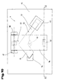
- Figs. 10 to 12 are finally more Embodiments of locking devices 62 a firearm 4, in particular a handgun 52 shown.
- the firearm is 4 in a lying position and in the area of Trigger guard 113 with a closure bracket 114 of comprises above and fixed on a support surface 115.
- a Stop element 116 and the barrel 53 of the firearm 4 assigned a holding element 117.
- the closure bar 114 is a schematically indicated pivot axis 118 by the effect, for example by a Torsion spring 112 from the support surface 115 parallel Location in an approximately vertical position pivoted up. The release of the closure strap 114 again takes place via a locking device 62, which is indicated only schematically.
- This locking device 62 can now, as shown with reference to FIGS. 11 and 12, different be educated. As shown in Figs. 11 and 12, is in the bearing surface 115 receiving housing 119 arranged the drive element 71 with the locking pin 66, wherein via the line 111 turn the connection manufactured with an identification device 16 is by means of the drive element 71, the Locking pin 66 from in the two embodiments shown in solid lines locking position in the drawn in dashed lines release position be adjusted against the action of the spring 110. Of course, any other can do this Drive element 71 may be arranged.
- the locking pin 66 now engages e.g. into an opposite 120 in the closure clip 114 and prevents that this by the action of the torsion spring 112 to pivoted the pivot axis 118 in its release position can be. While now in the embodiment 12 immediately after release by the identification device with the drive element 71 after retraction of the locking pin 66 namely when it comes out of the opposite 120, the closure clip 114 snaps up, requires it to release the opposite 120 and the locking pin 66, which is in the embodiment according to Fig. 11 is a swing arm, a movement on the contrary 120, which as under spring preload standing push button is formed in the direction the Auflageftumblee 115, so that the locking pin 66 and the opposite 120 disengage.
- the housing 119 and the support surface 115th can be attached to any component, for example in a Desk drawer, on a desk or one any other place or mounted in a vehicle be.
- any component for example in a Desk drawer, on a desk or one any other place or mounted in a vehicle be.
- Fig. 13 is a means 201 for storage and / or securing multiple items 202, in particular for valuables, data carrier 203, Documents 204 or the like., Shown in holding and / or Storage facilities 205, as in safes 206 and / or lockers and / or cassettes 207 and / or receptacles 208 are placed or on the holding and / or storage device 205 held are.
- Any of the stationary holding and / or storage facilities 205 is about locking devices 209, 210 lockable.
- a release of this Locking devices 209, 210 is only by an identification device 211, for example a Microprocessor or a computing unit, via electrical and / or mechanical release elements 212, 213 possible.
- release elements 212, 213 can either by appropriate circuit parts - driven about program parts of the identification device 211 - be formed and serve only, for example the power supply for the locking mechanism to interrupt or initiate so that the locking device 209, 210 by spring force opens, or it can be provided own drive elements be that the locking device 209, 210 Move to an open position, so that the removal at least one of the objects 202 of at least a holding and / or storage device 205 is possible.
- These mechanical / electrical elements, which form the release elements 212, 213, for example by electrically actuated tie rod magnets, Holding magnets, drive motors, linear drives or the like.
- the illustrated in this embodiment Device 201 further includes the mobile or portable holding and / or storage facilities 205 or cassettes 207 or receptacles 208 associated locking devices 214, with which an unauthorized removal of objects 202 at a safe 206 or the locker obstructing position can be prevented.
- These Locking devices 214 and their associated Release elements 215 are each in the Cassettes 207 and receptacles 208 installed, so that from the outside as possible for an experienced Viewers are not recognizable.
- the locking devices 209, 210 and 214 assigned Release elements 212, 213 and 215 may be formed can, it is also possible in an advantageous manner that the in the mobile or portable holding and / or storage facilities 205 arranged release elements 215 own identification device 216 is assigned.
- the connection between the identification device 211 and a user 217 is done now wirelessly connected to the identification device 211 Transmitter and / or receiver units 218 and a user-carried transmitting and / or receiving unit 219.
- Locking devices 209, 210 for controlling the Removal possibility of the objects 202 from the stationary holding and / or storage facilities 205 line connected and with the locking device 214 for controlling the accessibility on the objects 202 in the mobile holding and / or Storage facilities 205 wireless, for example, via radio, connected.
- Each of the identification devices 211 or 216 is either via a line 221 with a power system 222, for example accumulators 223, batteries or a public power grid wired or wireless over an alternating electric field 224 from the outside with energy provided.
- the identification device 211 or 216 can either be in the holding and storage facilities 205 installed or distanced in one of them, protected against unauthorized access area be arranged.
- the device 201 can be any objects 202, such as valuables, dangerous objects or secret data be secured.
- securities such as shares, Promissory notes, ect., Or works of art, such as paintings, etc., or jewelry, such as necklaces, Watches, rings, etc., or valuable collections, Cash or otherwise, secured against unauthorized removal become.
- databases or data carriers by means of To secure the device according to the invention, so the Establishment 201 Data processing equipment or computer networks assign and thus the insight into relevant Data or modification of important data to control.
- each holding and / or storage facility 205 so safes 206, lockers a locker, cassettes 207 and / or Receptacle 208, by a central identification device 211 be monitored - that in the area each holding and / or storage device 205 a separate transmitting and / or receiving unit 218, 220 is arranged, so that the respective object 202, ie the valuable object, the data carrier 203 and / or actually extract the document 204 only can be when the user's hand 217 in the immediate vicinity of the respective object 202 or to the holding and / or storage device 205 is located.
- Identification device 211 While now in the previous function the identification device 211 mostly on the basis of stationary holding and / or storage device 205, it should be noted that a similar or similar function or training of Identification device 211 also for the identification devices 216 is used, which is the mobile Holding and / or storage facilities 205 assigned is.
- the power supply system is preferred 222, in particular the accumulator 23, for operating the identification device 216 in FIG the cassette 207 and / or in the receptacle 208th built-in, and it is equally the transmitting and / or Receiving unit 219 of the user 217 suitable for the release element 215 of the locking device 214, for example, for the lid or the door the mobile holding and / or storage device 205, release or block.
- This locking device 214 does not have to be on the lid or the Door act, but can also directly on the object 202 act and release this for removal or lock.
- the holding and / or storage device 205 can therefore be designed such that a complete enclosure of the object to be protected 202 is avoided or the object to be protected 202 only with the locking device 209, 210; 214 interacts and with this movement connected is. This is especially for presentation purposes of valuables, such as jewelry, watches or watches Like., Advantageous, since these valuables on the one hand before unauthorized Removal are protected and still one Assessment or a selection is possible.
- the object to be secured 202 of a Retainer, e.g. a headband, on a presentation rack secured the locking device 209, 210; 214 and / or the identification device 211, 216 with the holding member in operative connection stands.
- Transponders 38 work, both in the field the identification device 211 as well as in the area the holding and / or storage device 205 and in the rooms in which worth protecting Items 202 are kept or accessed important data is possible and on the body of the authorized user 217, one of them separate
- transmission apparatus for the alternating field 224 so whenever the appropriate Transponder 38 in the range of this radiated coded or unique alternating field 224, an actuation of the release elements 212, 213 or 215 is possible.
- a constantly operational Identification device 211, 216 to ensure are the unmobilen and / or also stationary Holding and / or Storage Devices 205
- Chargers 243 assigned to the accumulators 223 taking advantage of the total capacity charge or maintain the full charge state.
- the charging devices 243 can either with the Accumulators 223 are in electrical contact or wirelessly via the alternating electromagnetic field 224 be supplied with electrical energy.
- the electric Supply or charging of accumulators 223 takes place automatically whenever the holding and / or storage devices 205 located at the respective charging station.
- the total useful life which depending on the capacity of the accumulators 223 and each according to energy consumption of the identification device 216 days may be available. Furthermore, eliminates additional manual maintenance, such. B. the manual contacting of the identification device 216 with the charger 243, since the charging process automatically by resetting the object 202 and / or the Hatte- and / or storage device 205 is initiated.
- Fig. 14 shows an enlarged view of Receiving container 208 and the cassette 207 according to Fig. 13, wherein for previously described already Parts same reference numerals are used.
- the identification device 216 is from invisible on the outside in a slot-shaped recess 244 in a container wall 245, in the container bottom or arranged in the container lid.
- the in the case of a self-power supply the identification device 216 existing accumulators 223 are also preferred Invisible arranged in the recess 244 and accessible via a closure lid 246 from the outside.
- a closure lid 246 from the outside.
- the printed circuit board of the arithmetic unit of the identification device 216 is preferably also in the recess 244 arranged.
- the locking device 214 which is preferred by an electrically actuated tie rod magnet is formed, is preferred in the field of Dekkels of the receiving container 208.
- the release element 215 can be moved by the tie rod magnet and thus an increase or a swing allow or deny the lid. To high locking forces with low unlocking forces and thus low electrical energy consumption To achieve it is possible to choose any Pawls known in the art and / or Insert locking mechanisms.
- the arrangement of the transmitting and / or receiving unit 220 be different to maximum transmission distances realize by a few centimeters to be able to.
- the transmitting and / or Receiving unit 219 in or on a wristwatch which usually on the left wrist is worn, are various arrangement options advantageous, which is a short distance between the associated transmitting and / or receiving units 219, 220 allow.
- the left hand for the opening of the receptacle 208 and is the wristwatch with the Transmitter and / or receiver unit 219 on the left wrist, such is the transmitting and / or receiving unit 220 preferably in the range of a handle for pivoting arranged the lid, as this at a Opening intent of the receptacle 208 of the Hand of an authorized user to be taken must and thus forcibly a comparatively short Distance is present.
- the locking device 214 After removal of the items 202 can the locking device 214 again in the Sleep mode can be set or activated.
- an object 202 for example a data carrier 203, stored in the receptacle 208 is or removed from the receptacle 208, can be detected by any sensors and the Identification device 216 as control information serve.
- the release element 215 moved into the retracted position and the lid, e.g. by spring force automatically jump up, creating a comfortable obstruction or automatic protection of the object 202 is enabled.
- Including the sensor which for example through optical photoelectric sensors, Hall sensors, Endlagenschafter or other from the state
- the art known donors may be formed is further the construction of a time recording system with logging the removal of the objects 202 possible.
- This is the sensor with the identification device 216 line connected and a timer device the same, for example, formed by a the microcontroller 225 associated timer module, provides the microcontroller 225 the time and / or Date information available.
- the thus determinable Withdrawal times, withdrawal periods or withdrawal days the objects 202 from the receptacle 208 are from the identification device 216 stored and can optionally have a Output device, such as e.g. a display, visualized or via a printer in paper form become.
- Figs. 15 and 16 are further different Arrangement possibilities of the transmitting and / or receiving unit 219 for the embodiment of a wristwatch shown, with the space requirement for the calculator and the necessary electronic components at the user 217 can be kept extremely small and their Integration with garment worn by user 217 and / or jewelry 239, such as a watch band 240, a watch case 241, a Ring 242, a belt buckle or the like, simple is possible.
- garment worn by user 217 and / or jewelry 239 such as a watch band 240, a watch case 241, a Ring 242, a belt buckle or the like, simple is possible.
- switching elements 247 on the Wristwatch be arranged, which the process or the state of the transmitting and / or receiving unit 219 or the entire device 201.
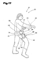
- Fig. 17 the user 217 of the device 201 shown. This carries a mobile holding and / or Storage device 205 with it inserted or valuables held on it and / or Weapons.
- the holding and / or storage device 205 for receiving the articles 202 is usually made of hard plastic and preferably on wrapped around the body of the user 217 Carrying strap 248 attached. If necessary, at the the Traggurt 248 opposite Stirnend Scheme the holding and / or storage device 205 a Connecting device 249, in particular in the form one wrapped around the thigh of the user 217 Bandes 250, arranged. Thus, the Holding and / or storage device 205 or the portable receptacle 208 with the body of the User 217 without affecting the wearing comfort tamper-proof connected.
- the object 202 to be secured is thereby by the holding and / or storage device 205 invisible or visible from transparent plastic enclosed or e.g. for presentation purposes only partially covered.
- the holding and / or storage device 205 Preferably, in an access area, the holding and / or storage device 205, the identification device 211 including all necessary Peripheral modules arranged.
- the send and / or Receiving unit 220 in particular in the form of a Transmitting and / or receiving coil 251, is at the in Hsymmetric Scheme the user 217 located girth 248 arranged and with the identification device 216 preferably conductively connected.
- the send and / or Receiving unit 220 or the transmitting and / or receiving coil 251 can be camouflaged as a fastening rivet between the holding and / or storage device 205 and the shoulder strap 248, whereby the presence of the device according to the invention 201 is not apparent.
- the locking device 214 is preferred in the holding and / or storage device 205 arranged and with the identification device 216 preferably conductively connected. Thus, when activated a drive element of the locking device 214 from the identification device 216 a locking pin occupy different positions and access to the item 202, e.g. Cash be granted or denied.
- the removal-assured state of the objects can only be positive Identification of the authorized user 217 canceled become.
- the user must 217 means that of the transmitting and / or receiving unit 219 assigned Identify identification code 230.
- the Transmitting and / or receiving unit 219 may be for this purpose camouflaged as a wristwatch, preferably on that wrist attached, which is the removal hand of the user 217 represents objects 202.
- the item 202 becomes automatic again about the holding and / or storage device 205 locked.
- the distance range between the transmitting and / or Receiving unit 219 and the transmitting and / or Receiver unit 220 is preferably to be set in such a way that with drooping or strolling arms the user 217, that is, when the send and / or Receiving unit 219 in the thigh area There is no unlocking of the object 202 takes place.
- the user 217 wants the item 202 grab, so is the send and / or Receiving unit 219 with the identification code 230 in the hip area, so in the immediate distance to Transmitting and / or receiving unit 220 on the support belt 248, which makes it particularly advantageous to have a distance of a few centimeters as the default value for the identification device 216 to set a suspension to be able to effect the withdrawal safeguard.
- a theft of the user's items 202 217 is thus also in a dense crowd of people excluded and still remains for the authorized user 217 an immediate action or action - free access to the Object 202 which, as shown schematically in FIG. 17, by cash in a money-storage facility or in a personal wallet of the user 217 can be formed.
- the device 201 a Assign alarm and / or signaling device, which on reception of the system unknown and thus the removal of items 202 deniedder Identification codes 230 is activated.
- a timing device with which the device 201 during working hours e.g. a person in the field, one Seller or a computer specialist and at other times, e.g. during the Night hours to prevent abuse, e.g. by thieves, spies or children lifting the Safety device is completely excluded.
- the device 201 according to the invention is corresponding the above explanations in different Operating modes operable.
- Hereinafter are single advantageous procedures for the Identification and operation of the device 201 are listed become:
- the operation of the locking device 209, 210; 214 in different Way possible. This is the case, for example, when sharing the locking device 209, 210; 214 possible, only a very short time to remove the Object 202 provide and that after expiration this period of time the item 202 immediately is locked. But it is also possible that over the Time period over which the user 217 determined in this particular Release area is located or in the specific Distance to the corresponding receiving point for the identification codes 230, the locking device 209, 210; 214 unchecked continuously remains.
- the Identification prior to release of the items 202 in more than two stages, so that different Criteria must be met before the release via the identification code 230 in accordance with great approach of the user 217 to the Objects 202 takes place. So it is possible, among other things - As shown in Fig. 14 can be seen - that a further Entriegelungsorgan 252 or a control device 253, e.g.
- a switching element or a sensor surface with the Identification device 211, 216 is connected and only if this additional unlocking organ 252 pressed and a positive identification over the Identification device 211, 216 sometimes by a small distance between the transmitting and / or receiving units 218 to 220 or the control device 253 provides a positive control result, the locking device 209, 210; 214 released becomes.
- Such unlocking member 252 which, for example, by a push button switch a light barrier or the like may be formed can, causes the release by the locking devices 209, 210; 214 only takes place even if the second hand or another body part in close proximity to the item 202 or to the holding and / or storage device 205 is located. This makes it an advantage for an observer of the authorized user 217 barely recognizable, which measures or steps are taken need to access or access the secured Obtain item 202.
- the repositioning of the object 202 semi-automatic, manual or fully automatic possible by either the approach of the article 202 to the holding and / or storage device 205 recognized and accordingly this is brought into an operating state, in which a insertion or insertion of the object 202 is possible.
- Block diagrams act in which individual Circuit details are not shown and with any known from the prior art components the electrical engineering or electronics are realized can.
Landscapes
- Engineering & Computer Science (AREA)
- General Engineering & Computer Science (AREA)
- Radar, Positioning & Navigation (AREA)
- Remote Sensing (AREA)
- Lock And Its Accessories (AREA)
- Input Circuits Of Receivers And Coupling Of Receivers And Audio Equipment (AREA)
- Preparation Of Clay, And Manufacture Of Mixtures Containing Clay Or Cement (AREA)
- Mobile Radio Communication Systems (AREA)
- Aiming, Guidance, Guns With A Light Source, Armor, Camouflage, And Targets (AREA)
Description
- Fig. 1
- Haltevorrichtungen und Verriegelungsvorrichtungen für Schußwaffen einer erfindungsgemäßen Sicherheitseinrichtung in vereinfachter, schematischer Darstellung;
- Fig. 2
- ein Blockschaltbild der Identifikafionsvorrichtung zur Überprüfung der Entnahme von Schußwaffen bzw. von Gegenständen aus den Halte- und/oder Aufbewahrungseinrichtungen in vereinfachter, schematischer Darstellung;
- Fig. 3
- eine Schußwaffe, in Seitenansicht, teilweise geschnitten, mit einer den Schußwaffengebrauch verifizierenden Sicherheitseinrichtung, in stark vereinfachter, schematischer Darstellung;
- Fig. 4
- eine Uhr mit verschiedenen Anordnungsmöglichkeiten einer Sende- und/oder Empfangseinheit einer erfindungsgemäßen Sicherheitseinrichtung, in vereinfachter, schematischer Darstellung;
- Fig. 5
- eine Haltevorrichtung der Sicherheitseinrichtung für Schußwaffen, teilweise geschnitten, in vereinfachter, schematischer Darstellung;
- Fig. 6
- einen Benutzer der Sicherheitseinrichtung mit einem erfindungsgemäß ausgestalteten Pistolenhalfter;
- Fig. 7
- eine andere Ausführungsvariante des Pistolenhalfters der erfindungsgemäßen Sicherheitseinrichtung, in vereinfachter, schematischer Darstellung;
- Fig. 8
- eine andere Ausführungsform einer erfindungsgemäß ausgebildeten Haltevorrichtung, mit einer dieser zugeordneten Identifikationsvorrichtung, in vereinfachter, schaubildlicher Darstellung;
- Fig. 9
- eine weitere Ausführungsvariante einer erfindungsgemäß ausgebildeten Sicherheitseinrichtung für eine Schußwaffe, in Seitenansicht, geschnitten und vereinfachter, schematischer Darstellung;
- Fig. 10
- eine mögliche Ausführungsform einer erfindungsgemäßen Sicherheitseinrichtung für eine Schußwaffe, in Draufsicht und vereinfachter Darstellung;
- Fig. 11
- die Sicherheitseinrichtung nach Fig. 10, in Stirnansicht, geschnitten und vereinfachter, schematischer Darstellung;
- Fig. 12
- eine andere Ausführungsform der Verriegelungsvorrichtung der Sicherheitseinrichtung nach Fig. 10, in Seitenansicht, geschnitten und stark vereinfachter, schematischer Darstellung;
- Fig. 13
- die erfindungsgemäße Einrichtung mit Halte- und/oder Aufbewahrungseinrichtungen für Gegenstände und diesen zugeordneten Verriegelungsvorrichtungen in vereinfachter, schematischer Darstellung;
- Fig. 14
- eine Halte- und/oder Aufbewahrungseinrichtung mit der die Öffnungsberechtigung verifizierenden, erfindungsgemäßen Sicherheitseinrichtung, in stark vereinfachter, schematischer Darstellung;
- Fig. 15
- eine Uhr mit verschiedenen Anordnungsmöglichkeiten einer Sende- und/oder Empfangseinheit einer erfindungsgemäßen Sicherheitseinrichtung in vereinfachter, schematischer Darstellung;
- Fig. 16
- einen Ring mit einer Sende- und/oder Empfangseinheit einer erfindungsgemäßen Sicherheitseinrichtung in vereinfachter, schematischer Darstellung;
- Fig. 17
- einen Benutzer der Einrichtung mit einer erfindungsgemäß ausgestalteten tragbaren Halte- und/oder Aufbewahrungseinrichtung.
- 1
- Sicherheitseinrichtung
- 2
- Schußwaffe
- 3
- Schußwaffe
- 4
- Schußwaffe
- 5
- Hattevorrichtung
- 6
- Haltevorrichtung
- 7
- Haltevorrichtung
- 8
- Aufnahmekasten
- 9
- Verriegelungsvorrichtung
- 10
- Verriegelungsvorrichtung
- 11
- Identifikationsvorrichtung
- 12
- Freigabeelement
- 13
- Freigabeelement
- 14
- Verriegelungsvorrichtung
- 15
- Freigabeelement
- 16
- Identifikationsvorrichtung
- 17
- Benutzer
- 18
- Sende- und/oder Empfangseinheit
- 19
- Sende- und/oder Empfangseinheit
- 20
- Sende- und/oder Empfangseinheit
- 21
- Leitung
- 22
- Energieversorgungssystem
- 23
- Akkumulator
- 24
- Wechselfeld
- 25
- Mikrocontroler
- 26
- Sendeeinrichtung
- 27
- Infrarotsensor
- 28
- Rechner
- 29
- Speicher
- 30
- Identifikationscode
- 31
- Antenne
- 32
- Erkennungssignal
- 33
- Verschlüsselungs- und/oder Entschlüsselungseinheit
- 34
- Verschlüsselungs- und/oder Entschlüsselungseinheit
- 35
- Speichereinheit
- 36
- Identifikationscode
- 37
- Entfernungsmeßvorrichtung
- 38
- Transponder
- 39
- Bekleidungs- und/oder Schmuckstück
- 40
- Uhrarmband
- 41
- Uhrgehäuse
- 42
- Abzug
- 43
- Ladevorrichtung
- 44
- Ausnehmung
- 45
- Gewehrkolben
- 46
- Abstützbereich
- 47
- Pufferelement
- 48
- Gewehrschaft
- 49
- Verschluß
- 50
- Bereich
- 51
- Schattelement
- 52
- Faustfeuerwaffe
- 53
- Lauf
- 54
- Halteteil
- 55
- Griff
- 56
- Wand
- 57
- Frontplatte
- 58
- Öffnung
- 59
- Aufnahme
- 60
- Verriegelungsvorrichtung
- 61
- Verriegelungsvorrichtung
- 62
- Verriegelungsvorrichtung
- 63
- Antriebselement
- 64
- Antriebselement
- 65
- Sperrzapfen
- 66
- Sperrzapfen
- 67
- Zielvorrichtung
- 68
- Ausnehmung
- 69
- Sperrzapfen
- 70
- Abzugsschutzbügel
- 71
- Antriebselement
- 72
- Sensor
- 73
- Sicherheitsbeamter
- 74
- Pistolenhalfter
- 75
- Traggurt
- 76
- Verbindungsvorrichtung
- 77
- Band
- 78
- Aufnahme
- 79
- Aufnahmebereich
- 80
- Sende- und/oder Empfangsspule
- 81
- Verschließvorrichtung
- 82
- Verschlußlatz
- 83
- Ende
- 84
- Ende
- 85
- Kupplungsvorrichtung
- 86
- Sperrdom
- 87
- Längsführung
- 88
- Längsschlitz
- 89
- Führungsschlitten
- 90
- Schwenkachse
- 91
- Schwenkarm
- 92
- Verriegelungsbügel
- 93
- Höhendistanz
- 94
- Führungstiefe
- 95
- Längsdistanz
- 96
- Seitenwange
- 97
- Durchbruch
- 98
- Pfeil
- 99
- Breite
- 100
- Stirnende
- 101
- Eritriegelungsorgan
- 102
- Ausnehmung
- 103
- Schlitten
- 104
- Längsachse
- 105
- Druckfeder
- 106
- Aufnahme
- 107
- Aufnahmeschlitz
- 108
- Sperriegel
- 109
- Schwenkachse
- 110
- Feder
- 111
- Leitung
- 112
- Torsionsfeder
- 113
- Abzugbügel
- 114
- Verschlußbügel
- 115
- Auflagefläche
- 116
- Anschlagelement
- 117
- Halteelement
- 118
- Schwenkachse
- 119
- Gehäuse
- 120
- Gegenteil
- 201
- Einrichtung
- 202
- Gegenstand
- 203
- Datenträger
- 204
- Dokumente
- 205
- Halte- und/oder Aufbewahrungseinrichtung
- 206
- Safe
- 207
- Kassette
- 208
- Aufnahmebehälter
- 209
- Verriegelungsvorrichtung
- 210
- Verriegelungsvorrichtung
- 211
- Identifikationsvorrichtung
- 212
- Freigabeelement
- 213
- Freigabeelement
- 214
- Verriegelungsvorrichtung
- 215
- Freigabeelement
- 216
- Identifikationsvorrichtung
- 217
- Benutzer
- 218
- Sende- und/oder Empfangseinheit
- 219
- Sende- und/oder Empfangseinheit
- 220
- Sende- und/oder Empfangseinheit
- 221
- Leitung
- 222
- Energieversorgungssystem
- 223
- Akkumulator
- 224
- Wechselfeld
- 225
- Mikrocontroler
- 230
- Identifikationscode
- 238
- Transponder
- 239
- Bekleidungs- und/oder Schmuckstück
- 240
- Uhrarmband
- 241
- Uhrgehäuse
- 242
- Ring
- 243
- Ladevorrichtung
- 244
- Ausnehmung
- 245
- Behälterwand
- 246
- Verschlußdeckel
- 247
- Schaltelement
- 248
- Traggurt
- 249
- Verbindungsvorrichtung
- 250
- Band
- 251
- Sende- und/oder Empfangsspule
- 252
- Entriegelungsorgan
- 253
- Kontrollvorrichtung
Claims (50)
- Einrichtung zum Sichern einer Schußwaffe gegen unbefugte Entnahme, mit einer Verriegelungsvorrichtung und einer Identifikationsvorrichtung, dadurch gekennzeichnet, daß die Identifikationsvorrichtung (11) zum drahtlosen Austausch zumindest von unverwechselbaren Identifikationscodes (30, 36) ausgebildet ist und zumindest eine einem befugten Benutzer (17) und eine weitere der Identifikationsvorrichtung (11) zugeordnete Sende- und/oder Empfangseinheit (18, 19) umfaßt und daß bei einer Distanz oder in einem Distanzbereich zwischen den Sende- und/oder Empfangseinheiten (18, 19) von 0 bis 1000 mm, bevorzugt 0 bis 50 mm, und übereinstimmenden Identifikationscodes (30, 36) der Sende- und/oder Empfangseinheit (19) des Benutzers (17) und der Sende- und/oder Empfangseinheit (18) der Identifikationsvorrichtung (11) die Verriegelungsvorrichtung (9, 10; 60, 61, 62) einer Haltevorrichtung (5, 6, 7) zur Halterung oder Aufnahme der Schußwaffe (2, 3, 4) durch die Identifikationsvorrichtung (11) deaktiviert ist.
- Einrichtung zum Sichern und/oder Aufbewahren von Gegenständen mit einer Sicherungseinrichtung gegen unbefugte Entnahme, die eine Verriegelungsvorrichtung und eine Identifikationsvorrichtung umfaßt, insbesondere nach Anspruch 1 dadurch gekennzeichnet, daß die Identifikationsvorrichtung (211, 216) zum drahtlosen Austausch zumindest von unverwechselbaren Identifikationscodes (230) ausgebildet ist und zumindest eine einem befugten Benutzer (217) und eine weitere der Identifikationsvorrichtung (211, 216) zugeordnete Sende- und/oder Empfangseinheit (218, 219, 220) umfaßt und daß bei einer Distanz oder in einem Distanzbereich zwischen den Sende- und/oder Empfangseinheiten (218, 219, 220) von 0 bis 1000 mm, bevorzugt 0 bis 50 mm und übereinstimmenden Identifikationscodes (230) der Sende- und/oder Empfangseinheit (219) des Benutzers (217) und der Sende- und/oder Empfangseinheit (218, 220) der Identifikationsvorrichtung (211, 216) die Verriegelungsvorrichtung (209, 210; 214) durch die Identifikationsvorrichtung (211, 216) deaktiviert ist.
- Einrichtung nach Anspruch 1 oder 2, dadurch gekennzeichnet, daß dem Benutzer (17,217) eine Sendeeinheit und der Identifikationsvorrichtung (11, 16, 211, 216) eine Empfangseinheit zugeordnet ist.
- Einrichtung nach einem oder mehreren der vorhergehenden Ansprüche, dadurch gekennzeichnet, daß dem Benutzer (17, 217) und/oder der identifikationsvorrichtung (11, 16, 211, 216) eine Sendeund Empfangseinheit (18,19, 20, 218, 219, 220) zugeordnet ist.
- Einrichtung nach einem oder mehreren der vorhergehenden Ansprüche, dadurch gekennzeichnet, daß die Sende- und/oder Empfangseinheit (18, 19, 20, 218, 219, 220) zur draht- losen Übertragung von Energie über ein elektromagnetisches Wechselfeld (24, 224) ausgebildet ist.
- Einrichtung nach einem oder mehreren der vorhergehenden Ansprüche, dadurch gekennzeichnet, daß die Sende- und/oder Empfangseinheit (19, 219) des Benutzers (17, 217) in einem Uhrgehäuse (41, 241), in einem Uhrarmband (40, 240) oder einem Ring (242) angeordnet ist.
- Einrichtung nach einem oder mehreren der vorhergehenden Ansprüche, dadurch gekennzeichnet, daß die Sende- und/oder Empfangseinheit (19, 219) in einem Bekleidungs- und/oder Schmuckstück (39, 239) des Benutzers (17, 217) integriert ist.
- Einrichtung nach einem oder mehreren der vorhergehenden Ansprüche, dadurch gekennzeichnet, daß die Sende- und/oder Empfangseinheit (19, 219) im Bereich der Hand bzw. des der Hand zugewandten Teils des Unterarms angeordnet ist.
- Einrichtung nach einem oder mehreren der vorhergehenden Ansprüche, dadurch gekennzeichnet, daß die Sende- und/oder Empfangseinheit (19, 219) des Benutzers (17, 217) zur kontinuierlichen bzw. kontinuierlich aufeinanderfolgenden, intermittierenden Signalabgabe ausgebildet ist.
- Einrichtung nach einem oder mehreren der vorhergehenden Ansprüche, dadurch gekennzeichnet, daß der Sende- und/oder Empfangseinheit (18, 19, 20, 218, 219, 220) ein manuell betätigbares Schaltelement (51, 247) zugeordnet ist.
- Einrichtung nach einem oder mehreren der vorhergehenden Ansprüche, dadurch gekennzeichnet, daß eine Reichweite der Sende- und/oder Empfangseinheit (18, 19, 20, 218, 219, 220) für die Übermittlung zumindest der Identifikationscodes (30, 36, 230) größer ist als die Distanz bzw. der Distanzbereich.
- Einrichtung nach einem oder mehreren der vorhergehenden Ansprüche, dadurch gekennzeichnet, daß die Sende- und/oder Empfangseinheit (19, 219) zur Ermittlung und gegebenenfalls Übermittlung ihrer Distanz zur Identifikationsvorrichtung (11, 16, 211, 216) aus- gebildet ist.
- Einrichtung nach einem oder mehreren der vorhergehenden Ansprüche, dadurch gekennzeichnet, daß die Distanz bzw. der Distanzbereich zwischen der Sende- und/ oder Empfangseinheit (19, 219) und der Sende- und/oder Empfangseinheit (18, 20, 218, 220) vorbe- stimmbar bzw. einstellbar ist.
- Einrichtung nach einem oder mehreren der vorhergehenden Ansprüche, dadurch gekennzeichnet, daß die Empfindlichkeit bzw. die Reichweite der Sende- und/oder Empfangseinheiten (18, 19, 20, 218, 219, 220) einstellbar ist.
- Einrichtung nach einem oder mehreren der vorhergehenden Ansprüche, dadurch gekennzeichnet, daß die Identifikationsvorrichtung (11, 16, 211, 216) optische und/oder akustische und/oder elektromagnetische Sende- und/oder Empfangseinheiten (18, 19, 20, 218, 219, 220) umfaßt.
- Einrichtung nach einem oder mehreren der vorhergehenden Ansprüche, dadurch gekennzeichnet, daß den Sende- und/oder Empfangseinheiten (18, 19, 20, 218, 219, 220) Verschlüsselungs- und/oder Entschlüsselungseinheiten (33, 34) zugeordnet sind.
- Einrichtung nach einem oder mehreren der vorhergehenden Ansprüche, dadurch gekennzeichnet, daß die Sende- und/oder Empfangseinheiten (18, 19, 20, 218, 219, 220) eine Prüfschaltung für das empfangene elektromagnetische Wechselfeld (24, 224) aufweisen.
- Einrichtung nach einem oder mehreren der vorhergehenden Ansprüche, dadurch gekennzeichnet, daß der Identifikationsvorrichtung (11, 16, 211, 216) und/oder der Sende- und/oder Empfangseinheit (19, 219) des Benutzers (17, 217) eine Entfernungsmeßvorrichtung (37) zugeordnet ist.
- Einrichtung nach einem oder mehreren der vorhergehenden Ansprüche, dadurch gekennzeichnet, daß die Verriegelungsvorrichtung (9, 10; 14) einer Haltevorrichtung (5, 6, 7) für die Schußwaffen (2, 3, 4) zugeordnet ist und eine Ladevorrichtung (43) bei der Haltevorrichtung (5, 6, 7) mit dem Energieversorgungssystem (22), bevorzugt der Identifikationsvorrichtung (16), gekoppelt ist.
- Einrichtung nach einem oder mehreren der vorhergehenden Ansprüche, dadurch gekennzeichnet, daß die Koppelung zwischen dem insbesondere durch Akkumulatoren (23, 223), gebildeten Energieversorgungssystem (22, 222) der Identifikationsvorrichtung (16, 216) und der Ladevorrichtung (43, 243) durch berührungslose Energieübertragungsvorrichtungen und/oder durch elektrische Kontaktvorrichtungen gebildet ist.
- Einrichtung nach einem oder mehreren der vorhergehenden Ansprüche, dadurch gekennzeichnet, daß die Haltevorrichtung (7) für eine Faustfeuerwaffe (52) eine Aufnahme (59) für einen Lauf (53) der Faustfeuerwaffe (52) umfaßt und die Verriegelungsvorrichtung (60, 61, 62) dem Lauf (53) zugeordnet ist.
- Einrichtung nach einem oder mehreren der vorhergehenden Ansprüche, dadurch gekennzeichnet, daß ein Antriebselement (63, 64, 71) der Verriegelungsvorrichtung (60, 61, 62) mit einem Sperrzapfen (65, 66, 69) gekoppelt ist und das Antriebselement (63, 64, 71) mit der Identifikationsvorrichtung (11) leitungsverbunden ist.
- Einrichtung nach einem oder mehreren der vorhergehenden Ansprüche, dadurch gekennzeichnet, daß der Sperrzapfen (65, 66, 69) von der Identitikationsvorrichtung (16) gesteuert mit dem Antriebselement (63, 64, 71) aus einer im Innenraum der Aufnahme (59) be- findlichen Position in eine außerhalb desselben befindliche Position verstellbar ist.
- Einrichtung nach einem oder mehreren der vorhergehenden Ansprüche, dadurch gekennzeichnet, daß der Sperrzapfen (65, 66, 69) mit einer Zielvorrichtung (67) und/oder einer Ausnehmung (68) und/oder einem Abzugsschutzbügel (70) zusammenwirkt.
- Einrichtung nach einem oder mehreren der vorhergehenden Ansprüche, dadurch gekennzeichnet, daß im Bereich einer Öffnung (58) der Aufnahme (59) bzw. im Bereich der Haltevorrichtung (5, 6, 7) ein Sensor angeordnet ist, welcher mit der Verriegelungsvorrichtung (60, 61, 62) bzw. der Identifikationsvorrichtung (16) leitungsverbunden ist.
- Einrichtung nach einem oder mehreren der vorhergehenden Ansprüche, dadurch gekennzeichnet, daß ein Halteteil (54) bzw. ein Griff (55) der Faustfeuerwaffe (52) aus der Haltevorrichtung (7) hervorragt.
- Einrichtung nach einem oder mehreren der vorhergehenden Ansprüche, dadurch gekennzeichnet, daß die Haltevorrichtung (7) durch einen Pistolenhalfter (74) gebildet ist und die Identifikationsvorrichtung (11) am Pistolenhalfter (74) angeordnet ist.
- Einrichtung nach einem oder mehreren der vorhergehenden Ansprüche, dadurch gekennzeichnet, daß der Pistolenhalfter (74) aus Hartkunststoff gebildet ist und der Sperrzapfen (69) der Verriegelungsvorrichtung (62) am Pistolenhalfter (74) in der Sperrstellung den Abzugschutzbügel (70) durchsetzt.
- Einrichtung nach einem oder mehreren der vorhergehenden Ansprüche,
dadurch gekennzeichnet, daß die Sende- und/oder Empfangseinheit (18) an einem Traggurt (75) des Pistolenhalfters (74) im Bereich des Griffes (55) angeordnet ist. - Einrichtung nach einem oder mehreren der vorhergehenden Ansprüche, dadurch gekennzeichnet, daß eine Verschließvorrichtung (81) des Pistolenhalfters (74) einen Griff (55) umschließt und über eine mit der Identifikationsvorrichtung (11) verbundene Kupplungsvorrichtung (85) eine Schwenkbewegung der Verschließvorrichtung (81) relativ zum Pistolenhalfter (74) freigegeben bzw. gesperrt ist.
- Einrichtung nach einem oder mehreren der vorhergehenden Ansprüche, dadurch gekennzeichnet, daß die Identifikationsvorrichtung (11, 16, 211, 216) eine Abtastvorrichtung für personenbezogene, körperspezifische Merkmale, wie z.B. Fingerabdruck, Irisabbildung, Gesichtsform bzw, Handform, aufweist.
- Einrichtung nach einem oder mehreren der vorhergehenden Ansprüche, dadurch gekennzeichnet, daß die Verriegelungsvorrichtung (9, 10; 14; 60; 61; 62, 209, 210, 214) durch die Identifikationsvorrichtung (11, 16, 211, 216) freigegeben ist, wenn zumindest ein körperliches, personenbezogenes Merkmal und ein Identifikationscode (30, 36, 230) übereinstimmt.
- Einrichtung nach einem oder mehreren der vorhergehenden Ansprüche, dadurch gekennzeichnet, daß die Identifikations- und/oder Verriegelungsvorrichtung (11, 16; 9, 10; 14; 60; 61; 62, 211, 216; 209, 210, 214) mit einem Alarmgeber verbunden ist.
- Einrichtung nach einem oder mehreren der vorhergehenden Ansprüche, dadurch gekennzeichnet, daß die Identifikations- und/oder Verriegelungsvorrichtung (11, 16; 9, 10; 14; 60; 61; 62, 211, 216; 209, 210, 214) und/oder ein Kraftfeld zur Energieversorgung durch die Anwesenheit einer Person in einem Raum, in dem die Haltevorrichtung (5, 6, 7) bzw. die Halte- und/oder Aufbewahrungsvorrichung (205) angeordnet ist, aktiviert ist.
- Einrichtung nach einem oder mehreren der vorhergehenden Ansprüche, dadurch gekennzeichnet, daß die Freigabe der Verriegelungsvorrichtung (9, 10; 14; 60; 61; 62, 209, 210; 214) über einen Zeitgeber blockierbar ist.
- Einrichtung nach einem oder mehreren der vorhergehenden Ansprüche, dadurch gekennzeichnet, daß die Schaltvorrichtung für die Verriegelungsund/oder Identffikationsvorrichtung (9, 10; 14; 60; 61; 62; 11, 16, 209, 210; 214; 211, 216) und/oder Energieversorgungs- vorrichtung über eine Fernsteuervorrichtung, insbesondere mit einem Stimmerkennungsmodul, aktivierbar ist.
- Einrichtung nach einem oder mehreren der vorhergehenden Ansprüche, dadurch gekennzeichnet, daß die Sende- und/oder Empfangseinheit (218, 220) im Bereich der zu sichernden Gegenstände (202) zur kontinuierlichen und/oder kontinuierlich aufeinanderfolgenden, intermittierenden Abgabe von Identifikationscodes (230) ausgebildet ist.
- Einrichtung nach einem oder mehreren der vorhergehenden Ansprüche, dadurch gekennzeichnet, daß die Verriegelungsvorrichtung (209, 210; 214) einer Halte- und/ oder Aufbewahrungseinrichtung (205) für die Gegenstände (202) zugeordnet ist und eine Ladevorrich- tung (243) bei der Halte- und/oder Aufbewahrungseinrichtung (205) mit dem Energieversorgungssystem (222) der Identifikationsvorrichtung (211, 216) gekoppelt ist.
- Einrichtung nach einem oder mehreren der vorhergehenden Ansprüche, dadurch gekennzeichnet, daß die Identifikationsvorrichtung (216) unsichtbar in der Halte- und/oder Aufbewahrungseinrichtung (205), z. B. gebildet durch einen Safe (206) oder eine Schließfachanlage, integriert ist.
- Einrichtung nach einem oder mehreren der vorhergehenden Ansprüche, dadurch gekennzeichnet, daß die Verriegelungsvorrichtung (209, 210; 214) einer Tür oder einem Deckel der Halte- und/oder Aufbewahrungseinrichtung (205) oder einem Halteorgan eines Präsentationsträgers zugeordnet ist.
- Einrichtung nach einem oder mehreren der vorhergehenden Ansprüche, dadurch gekennzeichnet, daß ein Antriebselement der Verriegelungsvorrichtung (209, 210; 214) mit einem Sperrzapfen gekoppelt ist und das Antriebselement mit der Identifikationsvorrichtung (211, 216) leitungsverbunden ist.
- Einrichtung nach einem oder mehreren der vorhergehenden Ansprüche, dadurch gekennzeichnet, daß der Sperrzapfen von der Identifikationsvorrichtung (211, 216) gesteuert aus einer den Gegenstand (202) versperrenden Position in eine den Gegenstand (202) freigebende Position und umgekehrt verstellbar ist.
- Einrichtung nach einem oder mehreren der vorhergehenden Ansprüche, dadurch gekennzeichnet, daß im Bereich der Halte- und/oder Aufbewahrungseinrichtung (205) und/oder im Aufbewahrungsbereich für den Gegenstand (202) ein Sensor angeordnet ist, welcher mit der Verriegelungsvorrichtung (209, 210; 214) bzw. der Identifikationsvorrichtung (211, 216) leitungsverbunden ist.
- Einrichtung nach einem oder mehreren der vorhergehenden Ansprüche, dadurch gekennzeichnet, daß die Halte- und/oder Aufbewahrungseinrichtung (205) durch einen tragbaren Aufnahmebehälter (208) gebildet ist und die Identifikationsvorrichtung (216) am Benutzer (217) oder am tragbaren Aufnahmebehälter (208) selbst angeordnet ist.
- Einrichtung nach einem oder mehreren der vorhergehenden Ansprüche, dadurch gekennzeichnet, daß die Sende- und/oder Empfangseinheit (220) an einem Traggurt (248) des tragbaren Aufnahmebehälters (208) angeordnet ist.
- Einrichtung nach einem oder mehreren der vorhergehenden Ansprüche, dadurch gekennzeichnet, daß die Identifikationsvorrichtung (211, 216) und/oder die Verriegelungsvorrichtung (209, 210; 214) in einem Safe (206) und/oder in einem Schließfach und/oder in einem Aufnahmebehälter (208), z.B. einer Kassette (207) angeordnet ist oder diesen zugeordnet ist.
- Einrichtung nach einem oder mehreren der vorhergehenden Ansprüche, dadurch gekennzeichnet, daß die Identifikationsvorrichtung (211, 216) und/oder die Verriegelungsvorrichtung (209, 210; 214) Halteorganen, z.B. einem Waltebügel für einen Wertgegenstand auf einem Präsentationsträger, zugeordnet ist.
- Einrichtung nach einem oder mehreren der vorhergehenden Ansprüche, dadurch gekennzeichnet, daß der Identifikationsvorrichtung (211, 216) und/oder der Verriegelungsvorrichtung (209, 210; 214) eine in einem von der Sende- und/oder Empfangseinheit (218, 220) für die Identifikationscodes (230) distanzierten Bereich angeordnete Kontrollvorrichtung (253) zugeordnet ist.
- Einrichtung nach einem oder mehreren der vorhergehenden Ansprüche, dadurch gekennzeichnet, daß die Verriegelungsvorrichtung (209, 210; 214) bei positivem Kontrollergebnis der Kontrollvorrichtung (253) und bei übereinstimmenden Identifikationscodes (230) deaktiviert ist.
- Einrichtung nach Anspruch 2, dadurch gekennzeichnet, daß sie zur Sicherung von Datenbeständen Datenverarbeitungsanlagen wie tragbaren Computern, stationären EDV-Anlagen und/oder Computernetzwerken oder Datenträgern zugeordnet ist.
Applications Claiming Priority (7)
| Application Number | Priority Date | Filing Date | Title |
|---|---|---|---|
| AT135196 | 1996-07-26 | ||
| AT135196 | 1996-07-26 | ||
| AT1351/96 | 1996-07-26 | ||
| AT53697 | 1997-04-01 | ||
| AT53697 | 1997-04-01 | ||
| AT536/97 | 1997-04-01 | ||
| PCT/AT1997/000174 WO1998004880A1 (de) | 1996-07-26 | 1997-07-25 | Einrichtung zum sichern einer schusswaffe sowie zum sichern und/oder aufbewahren von gegenständen |
Publications (3)
| Publication Number | Publication Date |
|---|---|
| EP0912871A1 EP0912871A1 (de) | 1999-05-06 |
| EP0912871B1 EP0912871B1 (de) | 2001-10-24 |
| EP0912871B2 true EP0912871B2 (de) | 2005-04-20 |
Family
ID=25593078
Family Applications (1)
| Application Number | Title | Priority Date | Filing Date |
|---|---|---|---|
| EP97932639A Expired - Lifetime EP0912871B2 (de) | 1996-07-26 | 1997-07-25 | Einrichtung zum sichern einer schusswaffe sowie zum sichern und/oder aufbewahren von gegenständen |
Country Status (6)
| Country | Link |
|---|---|
| EP (1) | EP0912871B2 (de) |
| AT (1) | ATE207603T1 (de) |
| AU (1) | AU3613097A (de) |
| CA (1) | CA2262100A1 (de) |
| DE (1) | DE59705100D1 (de) |
| WO (1) | WO1998004880A1 (de) |
Families Citing this family (15)
| Publication number | Priority date | Publication date | Assignee | Title |
|---|---|---|---|---|
| DE19755799B4 (de) * | 1997-12-16 | 2009-04-02 | Henry Tunger | Vorrichtung zur Aufnahme von Schusswaffen und Protokollierung deren Entnahme |
| GB2340589A (en) * | 1998-08-07 | 2000-02-23 | Hilary Barbara Cannon | Weapon security system |
| US6219952B1 (en) * | 1999-01-25 | 2001-04-24 | Jonathan E. Mossberg | Magnetic tag firearm safety enhancement system |
| BE1013085A3 (fr) | 1999-08-06 | 2001-09-04 | Fn Herstal Sa | Arme a feu pourvue d'un systeme d'autorisation. |
| WO2001018332A1 (de) * | 1999-09-06 | 2001-03-15 | Siemens Aktiengesellschaft | Aktivierung von gesicherten objekten |
| US6770059B1 (en) | 1999-10-28 | 2004-08-03 | Span-America Medical Systems, Inc. | Curved tip for an insertion device |
| IT1315835B1 (it) * | 2000-02-16 | 2003-03-26 | Luciano Albanesi | Sicurezza elettronica per arma da fuoco ed arma da fuoco incorporantela stessa. |
| DE10018369A1 (de) * | 2000-04-13 | 2001-10-25 | Joergen Brosow | Vorrichtung zum Auslösen eines Schusses aus einer Schußwaffe |
| DE10062239C2 (de) | 2000-12-14 | 2003-06-26 | Heckler & Koch Gmbh | Handfeuerwaffe mit individueller Kennung |
| DE10148676A1 (de) * | 2001-10-02 | 2003-04-24 | Gaston Glock | System zur Aktivierung einer Schusswaffe mit einer Identifikationseinrichtung |
| BR0318615A (pt) | 2003-11-21 | 2006-10-17 | Armatix Gmbh | dispositivo de segurança para armas e processo para proteger as armas providas com um dispositivo de segurança |
| DE102004025718B4 (de) | 2004-05-26 | 2009-01-15 | Heckler & Koch Gmbh | Schießanlagensicherung |
| EP1914502B1 (de) | 2006-10-20 | 2011-09-07 | Armatix GmbH | Umrüstbare Sicherheitsvorrichtung für Handfeuerwaffe und Methode, um eine Handfeuerwaffe zu sichern. |
| EP1936572A1 (de) | 2006-12-22 | 2008-06-25 | Armatix GmbH | Identifikationseinrichtung und Verfahren für den logischen und/oder physikalischen Zugang bzw. Zugriff auf eine Zieleinrichtung |
| CA2755545A1 (en) | 2009-02-05 | 2010-08-12 | Robert Gerard Mcnamara | A safety system for firearms |
Citations (4)
| Publication number | Priority date | Publication date | Assignee | Title |
|---|---|---|---|---|
| US4488370A (en) † | 1980-02-15 | 1984-12-18 | Lemelson Jerome H | Weapon control system and method |
| DE9207173U1 (de) † | 1992-05-27 | 1992-08-13 | Lauster, Peter, 7200 Tuttlingen | Elektronische Griffsicherung für Handfeuerwaffen |
| DE4303333A1 (de) † | 1992-12-24 | 1994-06-30 | Schreiber Hans | Verfahren und Bausatz zur legitimierten Betätigung von Schußwaffen |
| DE19511386C1 (de) † | 1995-03-28 | 1996-05-23 | Siemens Ag | Diebstahlschutzvorrichtung für ein Kraftfahrzeug |
Family Cites Families (6)
| Publication number | Priority date | Publication date | Assignee | Title |
|---|---|---|---|---|
| US5016376A (en) * | 1989-10-20 | 1991-05-21 | Pugh Kenneth J | Magnetic actuated firearms locking mechanism |
| US5062232A (en) * | 1990-02-23 | 1991-11-05 | Eppler Larry D | Safety device for firearms |
| US5168114A (en) * | 1991-12-13 | 1992-12-01 | Enget Jerome M | Automatic gun safety device |
| US5459957A (en) * | 1994-06-09 | 1995-10-24 | Winer; Guy T. | Gun security and safety system |
| US5461812A (en) * | 1994-11-16 | 1995-10-31 | Bennett; Emeric S. | Method and apparatus for a weapon firing safety system |
| DE4446020A1 (de) * | 1994-12-22 | 1996-06-27 | Mauser Werke Oberndorf Waffensysteme Gmbh | Einrichtung zur Erkennung von Waffe und berechtigtem Benutzer |
-
1997
- 1997-07-25 WO PCT/AT1997/000174 patent/WO1998004880A1/de not_active Ceased
- 1997-07-25 EP EP97932639A patent/EP0912871B2/de not_active Expired - Lifetime
- 1997-07-25 AU AU36130/97A patent/AU3613097A/en not_active Abandoned
- 1997-07-25 DE DE59705100T patent/DE59705100D1/de not_active Expired - Fee Related
- 1997-07-25 AT AT97932639T patent/ATE207603T1/de not_active IP Right Cessation
- 1997-07-25 CA CA002262100A patent/CA2262100A1/en not_active Abandoned
Patent Citations (4)
| Publication number | Priority date | Publication date | Assignee | Title |
|---|---|---|---|---|
| US4488370A (en) † | 1980-02-15 | 1984-12-18 | Lemelson Jerome H | Weapon control system and method |
| DE9207173U1 (de) † | 1992-05-27 | 1992-08-13 | Lauster, Peter, 7200 Tuttlingen | Elektronische Griffsicherung für Handfeuerwaffen |
| DE4303333A1 (de) † | 1992-12-24 | 1994-06-30 | Schreiber Hans | Verfahren und Bausatz zur legitimierten Betätigung von Schußwaffen |
| DE19511386C1 (de) † | 1995-03-28 | 1996-05-23 | Siemens Ag | Diebstahlschutzvorrichtung für ein Kraftfahrzeug |
Also Published As
| Publication number | Publication date |
|---|---|
| CA2262100A1 (en) | 1998-02-05 |
| WO1998004880A1 (de) | 1998-02-05 |
| AU3613097A (en) | 1998-02-20 |
| ATE207603T1 (de) | 2001-11-15 |
| EP0912871A1 (de) | 1999-05-06 |
| DE59705100D1 (de) | 2001-11-29 |
| EP0912871B1 (de) | 2001-10-24 |
Similar Documents
| Publication | Publication Date | Title |
|---|---|---|
| US6510642B2 (en) | Device for securing a firearm, as well as for securing and/or storing objects | |
| EP0912871B2 (de) | Einrichtung zum sichern einer schusswaffe sowie zum sichern und/oder aufbewahren von gegenständen | |
| EP1300647B1 (de) | System zur Aktivierung einer Schusswaffe mit einer Identifikationseinrichtung | |
| US11028636B2 (en) | Handgun mini-vault | |
| EP1307699B1 (de) | Elektronisches waffensicherungssystem und verfahren zum sichern einer feuerwaffe | |
| US9341424B2 (en) | Firearm locking assembly | |
| CA2926809C (en) | System for actuating gun and utility locks with an external mobile device | |
| DE60033745T2 (de) | Passives, magnetisches identifizierungsetikett für die verbesserung der feuerwaffensicherheit | |
| US7200965B2 (en) | Securing mechanisms for preventing access to a firearm by unauthorized users, and safety housings for use therewith | |
| US20010033228A1 (en) | Novel smart holster | |
| US20180274281A1 (en) | Portable safe | |
| WO2002081999A1 (en) | Securing mechanisms for preventing access to a firearm by unauthorized users, and safety housings for use therewith | |
| DE102013111429A1 (de) | Verfahren zum Betreiben eines Schließsystems sowie Schließsystem | |
| CN103106566B (zh) | 枪弹的存放管理控制方法及其存放管理控制系统 | |
| WO2004053422A1 (de) | Sicherungsvorrichtung und -verfahren für schusswaffen und patronen | |
| WO2015066744A1 (de) | Elektromechanische sperrvorrichtung für eine schusswaffe, um eine benutzung nur vom dazu berechtigten benutzer zu ermöglichen | |
| US20250225830A1 (en) | Intelligent locking system with electronical identification for a dangerous items repository | |
| DE3825051C1 (de) | ||
| DE19635784C2 (de) | Sicherheitstransportbehälter mit einer Alarmanlage und einer Sicherungstechnik für den Transport von Geld und Wertgegenständen | |
| WO2003001462A1 (de) | Transportbehältnis mit elektronischem transportsicherungsmechanismus für bargeld und wertgegenstände | |
| DE102010005004A1 (de) | Schusswaffe mit Schnittstelle für Schusswaffenmodule | |
| DE102012013870B4 (de) | Vorrichtung und Sicherungssystem für eine Handfeuerwaffe gegen unautorisierten Gebrauch, mit einem Waffenschloss | |
| Ram | Technology of Safety Devices for Firearms | |
| DE202010017506U1 (de) | Taschenschloss | |
| Jain | SMART FIREARM USING BIOMETRIC AND RFID SECURITY |
Legal Events
| Date | Code | Title | Description |
|---|---|---|---|
| PUAI | Public reference made under article 153(3) epc to a published international application that has entered the european phase |
Free format text: ORIGINAL CODE: 0009012 |
|
| 17P | Request for examination filed |
Effective date: 19990122 |
|
| AK | Designated contracting states |
Kind code of ref document: A1 Designated state(s): AT BE CH DE DK ES FI FR GB IE IT LI LU MC NL SE |
|
| AX | Request for extension of the european patent |
Free format text: SI PAYMENT 19990122 |
|
| GRAG | Despatch of communication of intention to grant |
Free format text: ORIGINAL CODE: EPIDOS AGRA |
|
| 17Q | First examination report despatched |
Effective date: 20000705 |
|
| GRAG | Despatch of communication of intention to grant |
Free format text: ORIGINAL CODE: EPIDOS AGRA |
|
| GRAG | Despatch of communication of intention to grant |
Free format text: ORIGINAL CODE: EPIDOS AGRA |
|
| GRAH | Despatch of communication of intention to grant a patent |
Free format text: ORIGINAL CODE: EPIDOS IGRA |
|
| GRAH | Despatch of communication of intention to grant a patent |
Free format text: ORIGINAL CODE: EPIDOS IGRA |
|
| GRAA | (expected) grant |
Free format text: ORIGINAL CODE: 0009210 |
|
| AK | Designated contracting states |
Kind code of ref document: B1 Designated state(s): AT BE CH DE DK ES FI FR GB IE IT LI LU MC NL SE |
|
| AX | Request for extension of the european patent |
Free format text: SI PAYMENT 19990122 |
|
| PG25 | Lapsed in a contracting state [announced via postgrant information from national office to epo] |
Ref country code: NL Free format text: LAPSE BECAUSE OF FAILURE TO SUBMIT A TRANSLATION OF THE DESCRIPTION OR TO PAY THE FEE WITHIN THE PRESCRIBED TIME-LIMIT Effective date: 20011024 Ref country code: IT Free format text: LAPSE BECAUSE OF FAILURE TO SUBMIT A TRANSLATION OF THE DESCRIPTION OR TO PAY THE FEE WITHIN THE PRESCRIBED TIME-LIMIT;WARNING: LAPSES OF ITALIAN PATENTS WITH EFFECTIVE DATE BEFORE 2007 MAY HAVE OCCURRED AT ANY TIME BEFORE 2007. THE CORRECT EFFECTIVE DATE MAY BE DIFFERENT FROM THE ONE RECORDED. Effective date: 20011024 Ref country code: IE Free format text: LAPSE BECAUSE OF FAILURE TO SUBMIT A TRANSLATION OF THE DESCRIPTION OR TO PAY THE FEE WITHIN THE PRESCRIBED TIME-LIMIT Effective date: 20011024 Ref country code: FR Free format text: LAPSE BECAUSE OF FAILURE TO SUBMIT A TRANSLATION OF THE DESCRIPTION OR TO PAY THE FEE WITHIN THE PRESCRIBED TIME-LIMIT Effective date: 20011024 Ref country code: FI Free format text: LAPSE BECAUSE OF FAILURE TO SUBMIT A TRANSLATION OF THE DESCRIPTION OR TO PAY THE FEE WITHIN THE PRESCRIBED TIME-LIMIT Effective date: 20011024 |
|
| REF | Corresponds to: |
Ref document number: 207603 Country of ref document: AT Date of ref document: 20011115 Kind code of ref document: T |
|
| REG | Reference to a national code |
Ref country code: CH Ref legal event code: EP |
|
| REG | Reference to a national code |
Ref country code: IE Ref legal event code: FG4D Free format text: GERMAN |
|
| REF | Corresponds to: |
Ref document number: 59705100 Country of ref document: DE Date of ref document: 20011129 |
|
| REG | Reference to a national code |
Ref country code: GB Ref legal event code: IF02 |
|
| PG25 | Lapsed in a contracting state [announced via postgrant information from national office to epo] |
Ref country code: SE Free format text: LAPSE BECAUSE OF FAILURE TO SUBMIT A TRANSLATION OF THE DESCRIPTION OR TO PAY THE FEE WITHIN THE PRESCRIBED TIME-LIMIT Effective date: 20020124 Ref country code: DK Free format text: LAPSE BECAUSE OF FAILURE TO SUBMIT A TRANSLATION OF THE DESCRIPTION OR TO PAY THE FEE WITHIN THE PRESCRIBED TIME-LIMIT Effective date: 20020124 |
|
| REG | Reference to a national code |
Ref country code: CH Ref legal event code: NV Representative=s name: ABP PATENTMARKETING GMBH |
|
| GBT | Gb: translation of ep patent filed (gb section 77(6)(a)/1977) |
Effective date: 20020130 |
|
| NLV1 | Nl: lapsed or annulled due to failure to fulfill the requirements of art. 29p and 29m of the patents act | ||
| PG25 | Lapsed in a contracting state [announced via postgrant information from national office to epo] |
Ref country code: ES Free format text: LAPSE BECAUSE OF FAILURE TO SUBMIT A TRANSLATION OF THE DESCRIPTION OR TO PAY THE FEE WITHIN THE PRESCRIBED TIME-LIMIT Effective date: 20020430 |
|
| PGFP | Annual fee paid to national office [announced via postgrant information from national office to epo] |
Ref country code: GB Payment date: 20020523 Year of fee payment: 6 |
|
| PG25 | Lapsed in a contracting state [announced via postgrant information from national office to epo] |
Ref country code: LU Free format text: LAPSE BECAUSE OF NON-PAYMENT OF DUE FEES Effective date: 20020725 |
|
| PLBQ | Unpublished change to opponent data |
Free format text: ORIGINAL CODE: EPIDOS OPPO |
|
| PG25 | Lapsed in a contracting state [announced via postgrant information from national office to epo] |
Ref country code: LI Free format text: LAPSE BECAUSE OF NON-PAYMENT OF DUE FEES Effective date: 20020731 Ref country code: CH Free format text: LAPSE BECAUSE OF NON-PAYMENT OF DUE FEES Effective date: 20020731 Ref country code: BE Free format text: LAPSE BECAUSE OF NON-PAYMENT OF DUE FEES Effective date: 20020731 |
|
| PLBI | Opposition filed |
Free format text: ORIGINAL CODE: 0009260 |
|
| REG | Reference to a national code |
Ref country code: IE Ref legal event code: FD4D |
|
| EN | Fr: translation not filed | ||
| PLBF | Reply of patent proprietor to notice(s) of opposition |
Free format text: ORIGINAL CODE: EPIDOS OBSO |
|
| 26 | Opposition filed |
Opponent name: GASTON GLOCK Effective date: 20020723 |
|
| PLBF | Reply of patent proprietor to notice(s) of opposition |
Free format text: ORIGINAL CODE: EPIDOS OBSO |
|
| BERE | Be: lapsed |
Owner name: *RIENER KARL STEFAN Effective date: 20020731 |
|
| PG25 | Lapsed in a contracting state [announced via postgrant information from national office to epo] |
Ref country code: MC Free format text: LAPSE BECAUSE OF NON-PAYMENT OF DUE FEES Effective date: 20030201 |
|
| REG | Reference to a national code |
Ref country code: CH Ref legal event code: PL |
|
| PLBF | Reply of patent proprietor to notice(s) of opposition |
Free format text: ORIGINAL CODE: EPIDOS OBSO |
|
| PLBB | Reply of patent proprietor to notice(s) of opposition received |
Free format text: ORIGINAL CODE: EPIDOSNOBS3 |
|
| PG25 | Lapsed in a contracting state [announced via postgrant information from national office to epo] |
Ref country code: GB Free format text: LAPSE BECAUSE OF NON-PAYMENT OF DUE FEES Effective date: 20030725 |
|
| GBPC | Gb: european patent ceased through non-payment of renewal fee |
Effective date: 20030725 |
|
| PLAY | Examination report in opposition despatched + time limit |
Free format text: ORIGINAL CODE: EPIDOSNORE2 |
|
| PLBC | Reply to examination report in opposition received |
Free format text: ORIGINAL CODE: EPIDOSNORE3 |
|
| PUAH | Patent maintained in amended form |
Free format text: ORIGINAL CODE: 0009272 |
|
| STAA | Information on the status of an ep patent application or granted ep patent |
Free format text: STATUS: PATENT MAINTAINED AS AMENDED |
|
| 27A | Patent maintained in amended form |
Effective date: 20050420 |
|
| AK | Designated contracting states |
Kind code of ref document: B2 Designated state(s): AT BE CH DE DK ES FI FR GB IE IT LI LU MC NL SE |
|
| AX | Request for extension of the european patent |
Extension state: SI |
|
| REG | Reference to a national code |
Ref country code: ES Ref legal event code: FD2A Effective date: 20020726 |
|
| PGFP | Annual fee paid to national office [announced via postgrant information from national office to epo] |
Ref country code: AT Payment date: 20050731 Year of fee payment: 9 |
|
| EN | Fr: translation not filed | ||
| PG25 | Lapsed in a contracting state [announced via postgrant information from national office to epo] |
Ref country code: AT Free format text: LAPSE BECAUSE OF NON-PAYMENT OF DUE FEES Effective date: 20060725 |
|
| PGFP | Annual fee paid to national office [announced via postgrant information from national office to epo] |
Ref country code: DE Payment date: 20100201 Year of fee payment: 13 |
|
| PG25 | Lapsed in a contracting state [announced via postgrant information from national office to epo] |
Ref country code: DE Free format text: LAPSE BECAUSE OF NON-PAYMENT OF DUE FEES Effective date: 20110201 |
|
| REG | Reference to a national code |
Ref country code: DE Ref legal event code: R119 Ref document number: 59705100 Country of ref document: DE Effective date: 20110201 |