EP0912420B1 - Container with pressure compensation holes - Google Patents
Container with pressure compensation holes Download PDFInfo
- Publication number
- EP0912420B1 EP0912420B1 EP97931672A EP97931672A EP0912420B1 EP 0912420 B1 EP0912420 B1 EP 0912420B1 EP 97931672 A EP97931672 A EP 97931672A EP 97931672 A EP97931672 A EP 97931672A EP 0912420 B1 EP0912420 B1 EP 0912420B1
- Authority
- EP
- European Patent Office
- Prior art keywords
- container
- inner bag
- outer container
- pressure compensation
- wall
- Prior art date
- Legal status (The legal status is an assumption and is not a legal conclusion. Google has not performed a legal analysis and makes no representation as to the accuracy of the status listed.)
- Expired - Lifetime
Links
Images

Classifications
-
- B—PERFORMING OPERATIONS; TRANSPORTING
- B65—CONVEYING; PACKING; STORING; HANDLING THIN OR FILAMENTARY MATERIAL
- B65D—CONTAINERS FOR STORAGE OR TRANSPORT OF ARTICLES OR MATERIALS, e.g. BAGS, BARRELS, BOTTLES, BOXES, CANS, CARTONS, CRATES, DRUMS, JARS, TANKS, HOPPERS, FORWARDING CONTAINERS; ACCESSORIES, CLOSURES, OR FITTINGS THEREFOR; PACKAGING ELEMENTS; PACKAGES
- B65D83/00—Containers or packages with special means for dispensing contents
- B65D83/0055—Containers or packages provided with a flexible bag or a deformable membrane or diaphragm for expelling the contents
-
- B—PERFORMING OPERATIONS; TRANSPORTING
- B65—CONVEYING; PACKING; STORING; HANDLING THIN OR FILAMENTARY MATERIAL
- B65D—CONTAINERS FOR STORAGE OR TRANSPORT OF ARTICLES OR MATERIALS, e.g. BAGS, BARRELS, BOTTLES, BOXES, CANS, CARTONS, CRATES, DRUMS, JARS, TANKS, HOPPERS, FORWARDING CONTAINERS; ACCESSORIES, CLOSURES, OR FITTINGS THEREFOR; PACKAGING ELEMENTS; PACKAGES
- B65D1/00—Containers having bodies formed in one piece, e.g. by casting metallic material, by moulding plastics, by blowing vitreous material, by throwing ceramic material, by moulding pulped fibrous material, by deep-drawing operations performed on sheet material
- B65D1/02—Bottles or similar containers with necks or like restricted apertures, designed for pouring contents
- B65D1/0207—Bottles or similar containers with necks or like restricted apertures, designed for pouring contents characterised by material, e.g. composition, physical features
- B65D1/0215—Bottles or similar containers with necks or like restricted apertures, designed for pouring contents characterised by material, e.g. composition, physical features multilayered
-
- Y—GENERAL TAGGING OF NEW TECHNOLOGICAL DEVELOPMENTS; GENERAL TAGGING OF CROSS-SECTIONAL TECHNOLOGIES SPANNING OVER SEVERAL SECTIONS OF THE IPC; TECHNICAL SUBJECTS COVERED BY FORMER USPC CROSS-REFERENCE ART COLLECTIONS [XRACs] AND DIGESTS
- Y10—TECHNICAL SUBJECTS COVERED BY FORMER USPC
- Y10S—TECHNICAL SUBJECTS COVERED BY FORMER USPC CROSS-REFERENCE ART COLLECTIONS [XRACs] AND DIGESTS
- Y10S215/00—Bottles and jars
- Y10S215/902—Vent
Definitions
- the invention relates to a coextrusion blow molding process Container consisting of an essentially rigid Outer container and an easily deformable inner bag each different, no welded connection to each other incoming thermoplastic, with a container opening and at least two pressure equalization openings in the wall of the outer container for pressure equalization in the space between the outer container and the inner bag when the inner bag contracts, when squeezing excess material on the ground the blow mold of the inner bag is closed by a bottom weld seam and this bottom weld in the also closed Bottom of the outer container is jammed.
- Such a container is described in DE 41 39 555 C2.
- this known container is at the bottom of the outer container an outwardly projecting web is formed, in which the Closing the blow mold material of the outer container merged because the material of the inner bag a damming effect in the area of the above web from the Pinch edge retracts inwards.
- This gets material of the outer container over part of the amount of the above Bridges in contact with each other, creating a closed Weld seam is created.
- the bottom weld seam of the inner bag is anchored in the adjoining area of the web.
- the jetty can an approximately kite-shaped cross-sectional shape, for example have, but also other, for example curved cross-sectional shapes of the web to a welded bottom seam of the Can lead outer container. Too much details of the manufacture of the known container is on DE 41 39 555 C2 directed.
- the bottom weld seam of the inner bag can also be applied to others Be attached to the bottom of the outer container, for example using a suitable slide in the blow mold.
- These pressure equalization openings on both sides lie in the circumferential direction of the container viewed in places that match the Intersection points of the bottom weld seam with the peripheral seam of the Align container. In other words, these pressure equalization openings are located in the circumferential direction on the cutting lines through the central longitudinal axis of the container and the bottom seam going plane with the peripheral wall of the container.
- this also includes the case that the bottom weld does not cover the entire diameter of the container extends, in this case the intersection points formed by a line extending the bottom weld are.
- the inner bag pulls in Horizontal section, i.e. in one to the longitudinal axis of the container vertical plane essentially star-shaped together when the Container content is spread.
- This contraction on four sides of the inner bag means that a relatively large negative pressure in the inner bag occurs - and of course regardless of the fact that by the Pressure equalization openings ambient air in the space between the outer container and inner bag - in other words, a relatively large collapse force is required to cause this star-shaped contraction and then to maintain.
- the quality of the container contents can be impaired by the permeation, while if there is a leak due to air entering the bag
- the pump may become inoperative or the contents of the tank may leak.
- EP 0 550 772 A discloses a container which is used for storing a Serves liquid from which components evaporate, even when the bottle is tightly closed. This can be, for example, oxygen, which escapes through the container wall, creating a vacuum in the bottle arises.
- the inner layer should contract in a certain shape. This certain shape is caused by the fact that one or more adhesive strips be arranged between the outer layer and the inner layer, the result have that in their areas the inner layer firmly with the outer layer stays connected.
- the present invention has for its object a container considered in such a way that the vacuum is reduced, which in the inner bag occurs after the filling substance has been released.
- the container according to the invention are - in the circumferential direction of the container considered - at least one on each side of the bottom weld Pressure equalization opening formed in the outer container, all Pressure equalization openings opposite the intersections of the bottom weld (or its extension) are offset with the peripheral wall of the outer container. It is preferred that the pressure equalization openings by about 900 to the Intersections are staggered, although the invention is not there is limited.
- the inner bag is no longer attached to four around 900 areas offset from each other from the outer container, but forms it a so-called "dog bone shape" during the contraction of the inner bag in which the inner bag is only on two opposite areas of the wall of the outer container lifts off, its center around 90o offset from the above-mentioned intersection points. That is, the inner bag is compressed increasingly flatter on both sides, where the central axis of the compressed cross-sectional shape approximately with the pinched bottom seam of the inner bag coincides.
- the two-sided Contraction of the inner bag is not only caused by this can be that exactly around 90o to the intersections mentioned offset pressure equalization openings are formed.
- This can rather, for example, in a particular case the material of the inner bag and its wall thickness dependent circumferential area, which is opposite the intersection points is offset, for example by two in Pressure compensation openings spaced apart from one another in the circumferential direction, the pair by about 80o each Intersections can be offset.
- the negative pressure can otherwise be the same Minimize boundary conditions by having two diametrically opposed ones Pressure equalization openings arranged on one level are at right angles to that through the bottom seam and the Longitudinal central axis of the container extending plane.
- These pressure equalization openings can be made through elongated incisions be formed in the wall of the outer container by this for example with a knife, punching tool or with a Lasers are cut into the wall, leaving one remaining inner wall section then by applying a compressive force can be torn open.
- This can be the case with a container whose outer wall has a wall thickness of approx. 0.7 to 0.9 mm has to be accomplished in such a way that with a a crescent-shaped incision on a circular guided knife is generated, the wall down to a remaining safety wall thickness cut by approx. 0.2 mm, which ensures that despite the tolerances that occur, the inner bag cannot be damaged.
- a stamp so strong against the outside wall on one side of the cut that the remaining wall section bursts.
- a pressure equalization opening be formed with a punch or with a laser.
- the pressure equalization openings can also be punctiform Bores or punctures are formed in the wall of the outer container be, the injection needle provided with a central bore may be in connection with a source of print media stands. If the puncture needle penetrates the wall of the outer container, at the moment of the passage from the wall of the Outer container is the pressure medium, for example can be air, water or a gel, so firmly against the Inner bag pressed so that it withdraws, so that the inner bag cannot be damaged by the injection needle.
- the pressure medium for example can be air, water or a gel
- the container according to the invention can be seen as a so-called Be wide-necked containers because of the pressure equalization openings not just in the shoulder area, but anywhere of the outer container can be formed.
- the container 1 shown in Fig. 1 contains a container neck 2 and a shoulder section 3. At the container opening 4 can a pump for dispensing the container contents is attached, without the invention being limited to this.
- the container can also be designed as a squeeze bottle in which the container wall squeezed by hand to dispense the contents of the container and the container can also be a so-called wide-neck container be without shoulder section.
- Fig. 2 shows a known container in which the delivery of the container contents required pressure equalization in the space between the outer container and the inner bag open shoulder seams 8 of the outer container 6 is carried out by a smooth, seamless squeezing of the blow mold in this Area are formed.
- the open shoulder seams 8 lie in the vertical plane 9 through the axis of the web 5 and the central longitudinal axis 10 of the container runs.
- the intersection of this level 9 with the The peripheral wall of the outer container 6 are shown in FIG Reference number 11 denotes.
- the inner bag is released as the contents of the container are released 7 in four growing areas of the Inner wall of the outer container, at the intersection 11 surrounding areas 12, on which - in the circumferential direction seen the air inlet to the pressure equalization and at areas offset by about 90 ° for this purpose. This has result in a star-like contraction form of the inner container educated.
- the contraction of the inner container 7 from four sides requires a relatively large collapse force, the one also relatively large negative pressure in the inner bag with which this form of contraction is maintained becomes. The result is a relatively large permeation, Leakage of the inner bag 7 and a proportionate large remaining amount that cannot be removed from the inner bag is.
- FIG. 4 shows a representation corresponding to FIG. 2 a container according to the invention 1.
- This container contains no open shoulder seams to equalize pressure, but to Level 9 or the position of the open shoulder seams 8 according to FIG. 2 positions offset by an angle ⁇ of 90 ° each two pressure equalization openings 14, which are purely schematic in FIG are marked.
- the contraction occurs only from two sides can of course not only be caused by the fact that the pressure equalization openings exactly 90o to the intersections 11 are offset. It is important that in the closer circumferential area to the intersections 11 no pressure equalization openings are located that detach the inner bag 7th cause of the wall of the outer container 6 in this area can.
- the bilateral contraction can of course also be done cause that on both sides of the pressure equalization openings 14 further pressure equalization openings are formed, but a sufficient circumferential distance from the intersection 11 must comply.
Abstract
Description
Die Erfindung betrifft einen im Coextrusionsblasverfahren hergestellten Behälter, bestehend aus einem im wesentlichen steifen Außenbehälter und einem leicht verformbaren Innenbeutel aus jeweils verschiedenartigen, keine Schweißverbindung miteinander eingehenden thermoplastischen Kunststoffen, mit einer Behälteröffnung und wenigstens zwei Druckausgleichsöffnungen in der Wand des Außenbehälters zum Druckausgleich im Zwischenraum zwischen dem Außenbehälter und dem Innenbeutel bei Kontraktion des Innenbeutels, wobei beim Abquetschen von Überschußmaterial am Boden der Blasform der Innenbeutel durch eine Bodenschweißnaht verschlossen und diese Bodenschweißnaht in den ebenfalls verschlossenen Boden des Außenbehälters eingeklemmt ist.The invention relates to a coextrusion blow molding process Container consisting of an essentially rigid Outer container and an easily deformable inner bag each different, no welded connection to each other incoming thermoplastic, with a container opening and at least two pressure equalization openings in the wall of the outer container for pressure equalization in the space between the outer container and the inner bag when the inner bag contracts, when squeezing excess material on the ground the blow mold of the inner bag is closed by a bottom weld seam and this bottom weld in the also closed Bottom of the outer container is jammed.
Ein derartiger Behälter ist in der DE 41 39 555 C2 beschrieben. Bei diesem bekannten Behälter ist am Boden des Außenbehälters ein nach außen vorstehender Steg ausgebildet, in dem beim Schließen der Blasform Material des Außenbehälters zusammengeführt wird, da sich das Material des Innenbeutels infolge einer Stauwirkung im Bereich des vorstehenden Stegs von der Abquetschkante nach innen zurückzieht. Hierdurch gelangt Material des Außenbehälters über ein Teil der Höhe des vorstehenden Stegs miteinander in Berührung, wodurch eine geschlossene Schweißnaht entsteht. Die Bodenschweißnaht des Innenbeutels ist in dem anschließenden Bereich des Stegs verankert. Der Steg kann dabei beispielsweise eine etwa drachenförmige Querschnittsform haben, wobei aber auch andere, beispielsweise gewölbte Querschnittsformen des Steges zu einer verschweißten Bodennaht des Außenbehälters führen können. Zu weiten Einzelheiten der Herstellung des vorbekannten Behälters wird auf die DE 41 39 555 C2 verwiesen.Such a container is described in DE 41 39 555 C2. In this known container is at the bottom of the outer container an outwardly projecting web is formed, in which the Closing the blow mold material of the outer container merged because the material of the inner bag a damming effect in the area of the above web from the Pinch edge retracts inwards. This gets material of the outer container over part of the amount of the above Bridges in contact with each other, creating a closed Weld seam is created. The bottom weld seam of the inner bag is anchored in the adjoining area of the web. The jetty can an approximately kite-shaped cross-sectional shape, for example have, but also other, for example curved cross-sectional shapes of the web to a welded bottom seam of the Can lead outer container. Too much details of the manufacture of the known container is on DE 41 39 555 C2 directed.
Die Bodenschweißnaht des Innenbeutels kann aber auch auf andere Weise am Boden des Außenbehälters befestigt werden, beispielsweise mittels geeigneter Schieber in der Blasform.The bottom weld seam of the inner bag can also be applied to others Be attached to the bottom of the outer container, for example using a suitable slide in the blow mold.
Bei dem vorbekannten Behälter werden die Druckausgleichsöffnungen am Außenbehälter dadurch ausgebildet, daß der schlauchförmige Rohling beim Schließen der Blasform im Schulterbereich abgequetscht wird, wobei hier das Material ohne Ausbildung eines vorstehenden Steges glatt abgequetscht wird, so daß die beiden Materialschichten des Außenbehälters nicht in Berührung miteinander gelangen, weil dies durch die dazwischen liegende Doppelschicht des Innenbeutels verhindert wird. Damit entstehen bei dem vorbekannten Behälter im Schulterbereich zwei unverschweißte Nähte bei dem Außenbehälter, die sich vom Schulterbereich bis zum Halsbereich erstrecken.In the previously known container, the pressure equalization openings formed on the outer container in that the tubular Blank when closing the blow mold in the shoulder area is squeezed, here the material without training protruding web is squeezed smoothly, so that the two Material layers of the outer container do not come into contact with each other because this is due to the double layer between them of the inner bag is prevented. With this arise at the previously known container in the shoulder area two unwelded Seams on the outer container that extend from the shoulder area extend to the neck area.
Diese beidseitigen Druckausgleichsöffnungen liegen in Umfangsrichtung des Behälters betrachtet an Stellen, die mit den Schnittpunkten der Bodenschweißnaht mit der Umfangsnaht des Behälters fluchten. Anders ausgedrückt, liegen diese Druckausgleichsöffnungen in Umfangsrichtung auf den Schnittlinien einer durch die Mittellängsachse des Behälters und die Bodennaht gehenden Ebene mit der Umfangswand des Behälters. These pressure equalization openings on both sides lie in the circumferential direction of the container viewed in places that match the Intersection points of the bottom weld seam with the peripheral seam of the Align container. In other words, these pressure equalization openings are located in the circumferential direction on the cutting lines through the central longitudinal axis of the container and the bottom seam going plane with the peripheral wall of the container.
Wenn oben von Schnittpunkten der Bodenschweißnaht mit der Umfangswand gesprochen ist, beinhaltet dies auch den Fall, daß sich die Bodenschweißnaht nicht über den gesamten Durchmesser des Behälters erstreckt, wodurch in diesem Fall die Schnittpunkte durch eine die Bodenschweißnaht verlängernde Linie gebildet sind.If at the top of intersections of the floor weld with the peripheral wall is spoken, this also includes the case that the bottom weld does not cover the entire diameter of the container extends, in this case the intersection points formed by a line extending the bottom weld are.
Bei Abgabe des Behälterinhalts beispielsweise mittels einer Pumpe verringert sich das Volumen des Innenbeutels, und es tritt zum Druckausgleich Luft aus der Umgebung des Behälters in den Zwischenraum zwischen Innenbeutel und Außenbehälter ein. Dabei verbleibt in dem Behälter stets ein gewisser Unterdruck, der die Kontraktion des Innenbeutels aufrecht erhält.When dispensing the container contents, for example by means of a Pump reduces the volume of the inner bag and it kicks in to equalize air from the surroundings of the container in the Space between inner bag and outer container. there there is always a certain negative pressure in the container which Maintains contraction of the inner bag.
Bei dem vorbekannten Behälter zieht sich der Innenbeutel im Horizontalschnitt, d.h. in einer zur Längsachse des Behälters senkrechten Ebene im wesentlichen sternförmig zusammen, wenn der Behälterinhalt ausgebracht wird. Dies bedeutet, daß sich der Innenbeutel an vier im wesentlichen jeweils paarweise gegenüberliegenden Stellen vom Außenbehälter löst, und zwar -in Umfangsrichtung gesehen- an den Druckausgleichsöffnungen und an den hierzu um jeweils 90o versetzten Umfangsbereichen. Mit zunehmender Kontraktion vergrößern sich dabei jeweils die vier abgelösten Bereiche, so daß in etwa die oben angesprochene Sternform entsteht.In the case of the known container, the inner bag pulls in Horizontal section, i.e. in one to the longitudinal axis of the container vertical plane essentially star-shaped together when the Container content is spread. This means that the Inner bags on four essentially opposite each other in pairs Detach from the outer container, namely in the circumferential direction seen - at the pressure equalization openings and at the for this purpose circumferential areas offset by 90o. With increasing Contraction increases the four detached Areas, so that roughly the above-mentioned star shape arises.
Diese Kontraktion an vier Seiten des Innenbeutels hat zur Folge, daß ein verhältnismäßig großer Unterdruck in dem Innenbeutel auftritt - und zwar natürlich ungeachtet dessen, daß durch die Druckausgleichsöffnungen Umgebungsluft in den Zwischenraum zwischen Außenbehälter und Innenbeutel eintritt - anders ausgedrückt, ist eine verhältnismäßige große Kollabierkraft erforderlich, um diese sternförmige Kontraktion hervorzurufen und dann aufrecht zu erhalten. This contraction on four sides of the inner bag means that a relatively large negative pressure in the inner bag occurs - and of course regardless of the fact that by the Pressure equalization openings ambient air in the space between the outer container and inner bag - in other words, a relatively large collapse force is required to cause this star-shaped contraction and then to maintain.
Je größer das Vakuum innerhalb des Innenbeutels ist, umso größer ist jedoch auch die Permeation durch die Wand des Innenbeutels und die Gefahr der Undichtigkeit. Durch die Permeation kann die Qualität des Behälterinhalts beeinträchtigt werden, während bei Auftreten von Undichtigkeit durch eintretende Luft in den Beutel die Pumpe funktionsunfähig werden oder der Behälterinhalt auslaufen kann.However, the greater the vacuum inside the inner bag, the greater it is permeation through the wall of the inner bag and the risk of leakage. The quality of the container contents can be impaired by the permeation, while if there is a leak due to air entering the bag The pump may become inoperative or the contents of the tank may leak.
Die EP 0 550 772 A offenbart einen Behälter, der zur Aufbewahrung einer Flüssigkeit dient, von der sich Bestandteile verflüchtigen, auch wenn die Flasche dicht verschlossen ist. Dabei kann es sich beispielsweise um Sauerstoff handeln, der durch die Behälterwand entweicht, wodurch ein Unterdruck in der Flasche entsteht.EP 0 550 772 A discloses a container which is used for storing a Serves liquid from which components evaporate, even when the bottle is tightly closed. This can be, for example, oxygen, which escapes through the container wall, creating a vacuum in the bottle arises.
Damit sich die Außenschicht des Behälters durch den Unterdruck nicht verformt, tritt Luft in den Zwischenraum zwischen Außenschicht und Innenschicht ein. Wenn die Innenschicht durch eine Bodenschweißnaht verschlossen ist, die beidseitig von einem Steg der Außenschicht überdeckt ist, tritt die Luft durch den überlappten Bereich der Innenschicht und der Außenschicht ein, wodurch sich die Innenschicht von der Außenschicht trennen kann, so daß allein die Innenschicht zusammengezogen und deformiert wird, während die Außenschicht durch den Unterdruck nicht verformt wird.So that the outer layer of the container is not deformed by the negative pressure, air enters the space between the outer layer and the inner layer. If the inner layer is closed by a bottom weld seam on both sides of a web of the outer layer is covered, the air passes through the overlapped Area of the inner layer and the outer layer, which creates the inner layer can separate from the outer layer, so that only the inner layer is contracted and deformed while the outer layer through the Vacuum is not deformed.
Die Innenschicht soll sich dabei in einer bestimmten Form zusammenziehen. Diese bestimmte Form wird dadurch hervorgerufen, daß ein oder mehrere Klebstreifen zwischen der Außenschicht und der Innenschicht angeordnet werden, die zur Folge haben, daß in ihren Bereichen die Innenschicht fest mit der Außenschicht verbunden bleibt.The inner layer should contract in a certain shape. This certain shape is caused by the fact that one or more adhesive strips be arranged between the outer layer and the inner layer, the result have that in their areas the inner layer firmly with the outer layer stays connected.
Der vorliegenden Erfindung liegt die Aufgabe zugrunde, einen Behälter der betrachteten Art so weiter zu entwickeln, daß der Unterdruck verringert ist, der in dem Innenbeutel nach Abgabe von Füllsubstanz auftritt. The present invention has for its object a container considered in such a way that the vacuum is reduced, which in the inner bag occurs after the filling substance has been released.
Diese Aufgabe wird erfindungsgemäß durch die Merkmale des Patentanspruchs 1 gelöst.This object is achieved according to the invention by the features of patent claim 1 solved.
Vorteilhafte Weiterbildungen der Erfindung sind in den Unteransprüchen gekennzeichnet.Advantageous developments of the invention are in the subclaims characterized.
Bei dem erfindungsgemäßen Behälter sind - in Umfangsrichtung des Behälters betrachtet - zu beiden Seiten der Bodenschweißnaht jeweils wenigstens eine Druckausgleichsöffnung in dem Außenbehälter ausgebildet, wobei alle Druckausgleichsöffnungen gegenüber den Schnittpunkten der Bodenschweißnaht (oder deren Verlängerung) mit der Umfangswand des Außenbehälters versetzt sind. Bevorzugt ist dabei, daß die Druckausgleichsöffnungen um etwa 900 zu den Schnittpunkten versetzt angeordnet sind, obwohl die Erfindung hierauf nicht beschränkt ist.In the container according to the invention are - in the circumferential direction of the container considered - at least one on each side of the bottom weld Pressure equalization opening formed in the outer container, all Pressure equalization openings opposite the intersections of the bottom weld (or its extension) are offset with the peripheral wall of the outer container. It is preferred that the pressure equalization openings by about 900 to the Intersections are staggered, although the invention is not there is limited.
Hierdurch wird erreicht, daß sich der Innenbeutel nicht mehr an vier etwa um 900 zueinander versetzten Bereichen von dem Außenbehälter ablöst, sondern es bildet sich eine sogenannte "Hundeknochenform" bei der Kontraktion des Innenbeutels aus, bei der sich der Innenbeutel nur an zwei gegenüberliegenden Bereichen von der Wand des Außenbehälters abhebt, deren Zentrum etwa um 90o versetzt zu den oben genannten Schnittpunkten liegt. D.h., der Innenbeutel wird beidseitig zunehmend flacher zusammengedrückt, wobei die Mittelachse der zusammengedrückten Querschnittsform in etwa mit der eingeklemmten Bodennaht des Innenbeutels zusammenfällt.This ensures that the inner bag is no longer attached to four around 900 areas offset from each other from the outer container, but forms it a so-called "dog bone shape" during the contraction of the inner bag in which the inner bag is only on two opposite areas of the wall of the outer container lifts off, its center around 90o offset from the above-mentioned intersection points. that is, the inner bag is compressed increasingly flatter on both sides, where the central axis of the compressed cross-sectional shape approximately with the pinched bottom seam of the inner bag coincides.
Diese nicht mehr von vier, sondern von zwei Seiten aus erfolgende Kontraktion des Innenbeutels hat zur Folge, daß der Unterdruck in dem Innenbeutel gegenüber der Ablösung an mehr als zwei Bereichen erheblich verringert wird. Verringert sind sowohl die Kollabierkraft, die den Beutel in die "Hundeknochenform" zusammenzieht, als auch der Unterdruck, der diese Form aufrecht erhält.This no longer from four, but from two sides Contraction of the inner bag has the consequence that the negative pressure in the inner bag against detachment on more than two Areas is significantly reduced. Both are reduced Collapse force that pulls the bag into the "dog bone shape" as well as the negative pressure that sustains this shape receives.
Infolgedessen wird die Permeation in den Innenbeutel verringert, die Gefahr von Undichtigkeit sinkt und die Restmenge in dem Innenbeutel wird verringert, die nicht austragbar ist.As a result, the permeation into the inner bag is reduced, the risk of leakage decreases and the residual amount in the Inner bag is reduced, which is not removable.
Es versteht sich, daß die nur von zwei Seiten aus erfolgende Kontraktion des Innenbeutels nicht nur dadurch hervorgerufen werden kann, daß exakt um 90o zu den genannten Schnittpunkten versetzte Druckausgleichsöffnungen ausgebildet werden. Diese können sich vielmehr in einem vom jeweiligen Einzelfall beispielsweise vom Material des Innenbeutels und dessen Wandstärke abhängigen Umfangsbereich befinden, der gegenüber den Schnittpunkten versetzt ist, beispielsweise durch jeweils zwei in Umfangsrichtung voneinander beabstandete Druckausgleichsöffnungen, die paarweise um jeweils ca. 80o zu den Schnittpunkten versetzt sein können.It is understood that the two-sided Contraction of the inner bag is not only caused by this can be that exactly around 90o to the intersections mentioned offset pressure equalization openings are formed. This can rather, for example, in a particular case the material of the inner bag and its wall thickness dependent circumferential area, which is opposite the intersection points is offset, for example by two in Pressure compensation openings spaced apart from one another in the circumferential direction, the pair by about 80o each Intersections can be offset.
Wesentlich ist, daß sich die Druckausgleichsöffnungen bei dem erfindungsgemäßen Behälter in Umfangsrichtung gesehen nicht mehr in dem engeren Bereich der Schnittpunkte der Bodenschweißnaht mit der Umfangswand befinden, sondern möglichst in einem um 90o versetzten Bereich, so daß sich der Innenbeutel zumindest bei der anfänglichen Kontraktion nicht mehr im Bereich der Schnittpunkte ablöst. Dieser Umfangsbereich ist bevorzugt um 45o bis 135o zu den Schnittpunkten versetzt.It is essential that the pressure compensation openings in the Containers according to the invention no longer seen in the circumferential direction in the narrower area of the intersection of the bottom weld with the peripheral wall, but if possible in a 90o offset area, so that the inner bag at least at the initial contraction no longer in the intersection area replaces. This circumferential range is preferably around 45o to 135o to the intersection.
Wie gesagt, läßt sich der Unterdruck bei ansonsten gleichen Randbedingungen dadurch minimieren, daß zwei diametral gegenüberliegende Druckausgleichsöffnungen in einer Ebene angeordnet sind, die im rechten Winkel zu der durch die Bodennaht und die Längsmittelachse des Behälters verlaufenden Ebene liegt.As I said, the negative pressure can otherwise be the same Minimize boundary conditions by having two diametrically opposed ones Pressure equalization openings arranged on one level are at right angles to that through the bottom seam and the Longitudinal central axis of the container extending plane.
Dabei können selbstverständlich auch mehrere Druckausgleichsöffnungen im Abstand übereinanderliegend auf jeder Seite der Bodenschweißnaht ausgebildet sein.Of course, several pressure equalization openings can also be used spaced one above the other on each side of the Bottom weld seam should be formed.
Diese Druckausgleichsöffnungen können durch längliche Einschnitte in die Wand des Außenbehälters gebildet sein, indem diese beispielsweise durch ein Messer, Stanzwerkzeug oder mit einem Laser in die Wand eingeschnitten sind, wobei ein verbleibender innerer Wandabschnitt anschließend durch Aufbringen einer Druckkraft aufgerissen werden kann. Dies kann beispielsweise bei einem Behälter, dessen Außenwand eine Wandstärke von ca. 0,7 bis 0,9 mm hat, in der Weise bewerkstelligt werden, daß mit einem auf einer Kreisbahn geführten Messer ein sichelförmiger Einschnitt erzeugt wird, der die Wand bis auf eine restliche Sicherheits-Wandstärke von ca. 0,2 mm durchtrennt, die gewährleistet, daß trotz der auftretenden Toleranzen der Innenbeutel nicht beschädigt werden kann. Anschließend kann beispielsweise ein Druckstempel so kräftig gegen die Außenwand an einer Seite des Schnitts gepreßt werden, daß der restliche Wandabschnitt aufplatzt. Auf ähnliche Weise kann eine Druckausgleichsöffnung mit einem Stanzwerkzeug oder mit einem Laser ausgebildet werden. These pressure equalization openings can be made through elongated incisions be formed in the wall of the outer container by this for example with a knife, punching tool or with a Lasers are cut into the wall, leaving one remaining inner wall section then by applying a compressive force can be torn open. This can be the case with a container whose outer wall has a wall thickness of approx. 0.7 to 0.9 mm has to be accomplished in such a way that with a a crescent-shaped incision on a circular guided knife is generated, the wall down to a remaining safety wall thickness cut by approx. 0.2 mm, which ensures that despite the tolerances that occur, the inner bag cannot be damaged. Then, for example a stamp so strong against the outside wall on one side of the cut that the remaining wall section bursts. In a similar way, a pressure equalization opening be formed with a punch or with a laser.
Die Druckausgleichsöffnungen können auch durch punktförmige Bohrungen oder Einstiche in die Wand des Außenbehälters gebildet sein, wobei die Einstechnadel mit einer zentralen Bohrung versehen sein kann, die mit einer Druckmediumquelle in Verbindung steht. Wenn die Einstechnadel die Wand des Außenbehälters durchdringt, wird im Augenblick des Durchtritts aus der Wand des Außenbehälters das Druckmedium, bei dem es sich beispielsweise um Luft, Wasser oder um ein Gel handeln kann, so fest gegen den Innenbeutel gedrückt, daß dieser zurückweicht, so daß der Innenbeutel durch die Einstechnadel nicht beschädigt werden kann.The pressure equalization openings can also be punctiform Bores or punctures are formed in the wall of the outer container be, the injection needle provided with a central bore may be in connection with a source of print media stands. If the puncture needle penetrates the wall of the outer container, at the moment of the passage from the wall of the Outer container is the pressure medium, for example can be air, water or a gel, so firmly against the Inner bag pressed so that it withdraws, so that the inner bag cannot be damaged by the injection needle.
Zum Druckausgleich reichen sehr kleine, kapillarartige öffnungen, die auf die vorstehend beschriebene Weise an den gewünschten Stellen des Außenbehälters ausgebildet sein können.Very small, capillary-like openings are sufficient to equalize the pressure, to the desired ones in the manner described above Places of the outer container can be formed.
Der erfindungsgemäße Behälter kann dabei ersichtlich ein sogenannter Weithalsbehälter sein, da die Druckausgleichsöffnungen nicht nur im Schulterbereich, sondern an jeder beliebigen Stelle des Außenbehälters ausgebildet werden können.The container according to the invention can be seen as a so-called Be wide-necked containers because of the pressure equalization openings not just in the shoulder area, but anywhere of the outer container can be formed.
Die Erfindung wird nachfolgend anhand der Zeichnung näher beschrieben. Dabei zeigen:
- Fig. 1
- einen Vertikalschnitt durch einen im Coextrusionsblasen hergestellten Behälter der betrachteten Art;
- Fig. 2
- eine perspektivische Ansicht eines bekannten Behälters mit offenen Schulternähten;
- Fig. 3
- einen Horizontalschnitt durch den Behälter gemäß Fig. 2 oberhalb der eingeklemmten Bodennaht des Innenbeutels in einem Zustand, in dem sich der Innenbeutel zusammengezogen hat;
- Fig. 4
- eine perspektivische Ansicht eines erfindungsgemäßen Behälters in einer Fig. 2 entsprechenden Darstellung und
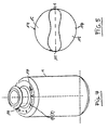
- Fig. 5
- einen Horizontalschnitt durch den Behälter gemäß Fig. 4 in einer der Fig. 3 entsprechenden Darstellung.
- Fig. 1
- a vertical section through a container produced in the coextrusion blow molding of the type under consideration;
- Fig. 2
- a perspective view of a known container with open shoulder seams;
- Fig. 3
- a horizontal section through the container of Figure 2 above the pinched bottom seam of the inner bag in a state in which the inner bag has contracted.
- Fig. 4
- a perspective view of a container according to the invention in a Fig. 2 corresponding representation and
- Fig. 5
- a horizontal section through the container of FIG. 4 in a representation corresponding to FIG. 3.
Der in Fig. 1 dargestellte Behälter 1 enthält einen Behälterhals 2 und einen Schulterabschnitt 3. An der Behälteröffnung 4 kann eine Pumpe zum Ausbringen des Behälterinhalts befestigt sein, ohne daß die Erfindung hierauf beschränkt ist. Der Behälter kann auch als Quetschflasche ausgestaltet sein, bei der die Behälterwand von Hand zur Abgabe des Behälterinhalts zusammengedrückt wird, und der Behälter kann auch ein sogenannter Weithalsbehälter ohne Schulterabschnitt sein.The container 1 shown in Fig. 1 contains a container neck 2 and a shoulder section 3. At the container opening 4 can a pump for dispensing the container contents is attached, without the invention being limited to this. The container can also be designed as a squeeze bottle in which the container wall squeezed by hand to dispense the contents of the container and the container can also be a so-called wide-neck container be without shoulder section.
Am Boden des Behälters ist -bevorzugt infolge des Schließens der Blasform- ein vorstehender, querschnittlich etwa drachenförmiger Steg 5 ausgebildet, in dessen in der Figur unterem Bereich sich die Materialschichten des Außenbehälters 6 (siehe Fig. 3) berühren, da sich in dem Formhohlraum des Steges die beiden abgequetschten Materialschichten des Innenbeutels 7 ein wenig von der Trennstelle nach oben zurückgezogen haben. Die beim Abquetschvorgang gebildete Schweißnaht des Innenbeutels ist in dem oberen Bereich des Stegs 5 eingeklemmt und damit in axialer Richtung gehalten.At the bottom of the container is preferred due to the closure of the Blow mold - a protruding, cross-sectionally dragon-shaped Web 5 formed, in the lower area in the figure touch the material layers of the outer container 6 (see FIG. 3), since the two squeezed out in the mold cavity of the web Material layers of the inner bag 7 a little bit of have withdrawn the separation point upwards. The one during the squeezing process formed weld seam of the inner bag is in the clamped upper area of the web 5 and thus in the axial Direction kept.
Fig. 2 zeigt einen bekannten Behälter, bei dem der zur Abgabe
des Behälterinhalts erforderliche Druckausgleich in dem Zwischenraum
zwischen den Außenbehälter und dem Innenbeutel durch
offene Schulternähte 8 des Außenbehälters 6 erfolgt, die durch
einen glatten, steglosen Abquetschvorgang der Blasform in diesem
Bereich ausgebildet sind. Fig. 2 shows a known container in which the delivery
of the container contents required pressure equalization in the space
between the outer container and the inner bag
Die offenen Schulternähte 8 liegen dabei in der vertikalen Ebene
9, die durch die Achse des Stegs 5 und die Mittellängsachse 10
des Behälters verläuft. Die Schnittpunkte dieser Ebene 9 mit der
Umfangswand des Außenbehälters 6 sind in der Fig. 3 mit dem
Bezugszeichen 11 bezeichnet.The
Im Verlaufe der Abgabe des Behälterinhalts löst sich der Innenbeutel
7 an vier zunehmend größer werdenden Bereichen von der
Innenwand des Außenbehälters ab, und zwar an den die Schnittpunkte
11 umgebenden Bereichen 12, an denen -in Umfangsrichtung
des Behälters gesehen die Luft zum Druckausgleich eintrittsowie
an hierzu um etwa 90o versetzten Bereichen 13. Dies hat
zur Folge, daß sich eine sternartige Kontraktionsform des Innenbehälters
ausgebildet.The inner bag is released as the contents of the container are released
7 in four growing areas of the
Inner wall of the outer container, at the
Das Zusammenziehen des Innenbehälters 7 von vier Seiten aus
erfordert eine verhältnismäßig große Kollabierkraft, der ein
ebenfalls verhältnismäßig großer Unterdruck in dem Innenbeutel
entspricht, mit dem diese Kontraktionsform aufrecht erhalten
wird. Die Folge sind eine verhältnismäßig große Permeation,
Gefahr der Undichtigkeit des Innenbeutels 7 sowie eine verhältnismäßig
große Restmenge, die nicht aus dem Innenbeutel austragbar
ist.The contraction of the
Fig. 4 zeigt in einer der Fig. 2 entsprechenden Darstellung
einen erfindungsgemäßen Behälter 1. Dieser Behälter enthält
keine offenen Schulternähte zum Druckausgleich, sondern an zur
Ebene 9 bzw. zur Lage der offenen Schulternähte 8 gemäß Fig. 2
um einen Winkel α von jeweils 90o versetzt liegenden Stellen
zwei Druckausgleichsöffnungen 14, die in Figur 5 rein schematisch
markiert sind. FIG. 4 shows a representation corresponding to FIG. 2
a container according to the invention 1. This container contains
no open shoulder seams to equalize pressure, but to
Level 9 or the position of the
Da im Bereich der Schnittpunkte 11 keine Druckausgleichsöffnungen
vorgesehen sind, löst sich bei Abgabe des Behälterinhalts
der Innenbeutel 7 hier nicht von der Innenwand des Außenbehälters
6 ab, d.h. es entstehen keine Kontraktionsabschnitte 12 der
sternförmigen Kontraktion gemäß Fig. 3. Der Innenbeutel 7 zieht
sich nur von zwei Seiten zusammen, wobei dieser Bereich sich
zunehmend um die Druckausgleichsöffnungen 14 herum ausbreitet
und in Figur 5 mit dem Bezugszeichen 15 gekennzeichnet ist.
Dabei bildet sich zunehmend eine sogenannte "Hundeknochenform"
der Innenbeutelkontraktion heraus.Since there are no pressure equalization openings in the area of the intersection points 11
are provided, dissolves when the contents of the container are dispensed
the
Diese nur von zwei Seiten erfolgende Kontraktion des Innenbeutels hat zur Folge, daß sie nur eine geringere Kollabierkraft erfordert, der ein ebenfalls geringerer Unterdruck zur Aufrechterhaltung der Kontraktionsform entspricht. Die Folge sind geringere Permeation, eine ebenfalls verringerte Gefahr der Undichtigkeit und eine kleinere Restmenge, die nicht austragbar ist.This contraction of the inner bag, which occurs only from two sides has the consequence that they have a lower collapse which also requires a lower vacuum to maintain corresponds to the form of contraction. The result is lower permeation, also a reduced risk of Leakage and a smaller residual amount that cannot be discharged is.
Es wird betont, daß die nur von zwei Seiten erfolgende Kontraktion
natürlich nicht nur dadurch hervorgerufen werden kann, daß
die Druckausgleichsöffnungen exakt um 90o zu den Schnittpunkten
11 versetzt ausgebildet sind. Wichtig ist, daß sich in dem
näheren Umfangsbereich zu den Schnittpunkten 11 keine Druckausgleichsöffnungen
befinden, die ein Ablösen des Innenbeutels 7
von der Wand des Außenbehälters 6 in diesem Bereich verursachen
können. Die zweiseitige Kontraktion läßt sich natürlich auch
dadurch hervorrufen, daß zu beiden Seiten der Druckausgleichsöffnungen
14 weitere Druckausgleichsöffnungen ausgebildet sind,
die aber einen genügenden Umfangsabstand von den Schnittpunkten
11 einhalten müssen.It is emphasized that the contraction occurs only from two sides
can of course not only be caused by the fact that
the pressure equalization openings exactly 90o to the
Claims (5)
- A container (1) produced in a coextrusion blowing process comprising a substantially rigid outer container and a readily deformable inner bag (7) of different thermoplastic plastic materials, which do not enter into a welded connection with one another, with a container opening (4) with at least two pressure compensation openings (14) in the wall of the outer container (6) for pressure compensation in the gap between the outer container (6) and the inner bag (7) on contraction of the inner bag, whereby for the purpose of squeezing out excess material on the base of the blow mould, the inner bag (7) is sealed by a bottom seam weld (5) and this bottom seam weld (5) is clamped in a bottom seam weld (5), which is also sealed, of the outer container (6), characterised in that at least one pressure compensation opening (14) is formed on both sides of the bottom seam weld (5) and that all the pressure compensation openings (14) are formed at positions on the outer container (6) which are substantially offset in the peripheral direction with respect to the intersection points (11) of the bottom seam weld (5) with the peripheral wall of the outer container (6) so that when the container content is delivered, the inner bag (7) contracts only from two sides.
- A container as claimed in Claim 1 characterised in that at least one respective pressure compensation opening (14) is formed offset by about 90° from the intersection points (11).
- A container as claimed in one of Claims 1 or 2, characterised in that at least two respective pressure compensation openings (14) are formed spaced apart and situated above one another offset by about 90° from the intersection, points (11).
- A container as claimed in one of Claims 1 to 3, characterised in that the pressure compensation openings (14) are formed by elongate cuts into the wall of the outer container (6).
- A container as claimed in one of Claims 1 to 3, characterised in that the pressure compensation openings (14) are formed by punctiform bores or perforations in the wall of the outer container (6).
Priority Applications (1)
| Application Number | Priority Date | Filing Date | Title |
|---|---|---|---|
| SI9730621T SI0912420T1 (en) | 1996-07-04 | 1997-06-27 | Container with pressure compensation holes |
Applications Claiming Priority (3)
| Application Number | Priority Date | Filing Date | Title |
|---|---|---|---|
| DE19626968 | 1996-07-04 | ||
| DE19626968A DE19626968A1 (en) | 1996-07-04 | 1996-07-04 | Container with pressure equalization opening |
| PCT/DE1997/001348 WO1998001366A1 (en) | 1996-07-04 | 1997-06-27 | Container with pressure compensation holes |
Publications (2)
| Publication Number | Publication Date |
|---|---|
| EP0912420A1 EP0912420A1 (en) | 1999-05-06 |
| EP0912420B1 true EP0912420B1 (en) | 2003-12-17 |
Family
ID=7798927
Family Applications (1)
| Application Number | Title | Priority Date | Filing Date |
|---|---|---|---|
| EP97931672A Expired - Lifetime EP0912420B1 (en) | 1996-07-04 | 1997-06-27 | Container with pressure compensation holes |
Country Status (11)
| Country | Link |
|---|---|
| US (1) | US6109468A (en) |
| EP (1) | EP0912420B1 (en) |
| JP (1) | JP3935213B2 (en) |
| AT (1) | ATE256614T1 (en) |
| AU (1) | AU717167B2 (en) |
| CA (1) | CA2258853A1 (en) |
| DE (3) | DE19626968A1 (en) |
| DK (1) | DK0912420T3 (en) |
| ES (1) | ES2213218T3 (en) |
| PT (1) | PT912420E (en) |
| WO (1) | WO1998001366A1 (en) |
Cited By (3)
| Publication number | Priority date | Publication date | Assignee | Title |
|---|---|---|---|---|
| DE102010024980A1 (en) | 2010-06-24 | 2011-12-29 | Gaplast Gmbh | Container with inner bag |
| DE202021103382U1 (en) | 2021-06-23 | 2021-08-31 | Gaplast Gmbh | container |
| EP4108415A1 (en) | 2021-06-23 | 2022-12-28 | Gaplast GmbH | Method for producing a container |
Families Citing this family (15)
| Publication number | Priority date | Publication date | Assignee | Title |
|---|---|---|---|---|
| US6503440B2 (en) * | 2000-04-07 | 2003-01-07 | Boehringer Ingelheim Pharma Kg | Process for making a container with a pressure equalization opening and containers produced accordingly |
| DE10256015B4 (en) * | 2002-11-30 | 2005-04-14 | Gaplast Gmbh | Method for producing a container with at least one pressure equalization opening |
| FR2891529B1 (en) * | 2005-10-04 | 2007-12-07 | Valois Sas | RECOVERY ORGAN, PROCESS FOR PRODUCING SUCH ORGAN AND DISPENSER COMPRISING SUCH AN ORGAN |
| DE102006012487B4 (en) * | 2006-03-16 | 2008-08-21 | Gaplast Gmbh | Method and device for producing a container |
| US20150266621A1 (en) | 2007-04-19 | 2015-09-24 | Anheuser-Busch Inbev S.A. | Integrally Blow-Moulded Bag-in-Container Having Interface Vents Opening to the Atmosphere at Location Adjacent to Bag's Mouth, Preform for Making It; and Processes for Producing the Preform and Bag-in-Container |
| US20080257883A1 (en) | 2007-04-19 | 2008-10-23 | Inbev S.A. | Integrally blow-moulded bag-in-container having an inner layer and the outer layer made of the same material and preform for making it |
| GB2459852B (en) * | 2008-05-06 | 2011-02-16 | Toly Products | Compact liquid cosmetics |
| RU2488481C2 (en) * | 2008-10-17 | 2013-07-27 | Дзе Жиллетт Компани | Device for removal of hair with liquid dosage |
| BR112012026193A2 (en) | 2010-04-15 | 2016-07-05 | Gillette Co | hair removal and fluid dispensing device |
| EP3126251A4 (en) | 2014-04-02 | 2018-01-03 | Kuvee, Inc. | Container for preserving liquid contents |
| EP3235747B1 (en) | 2014-12-19 | 2019-05-15 | Kyoraku Co., Ltd. | Delamination container and method for attaching a cap thereto |
| US10472162B2 (en) | 2016-09-09 | 2019-11-12 | The Clorox Company | Continuous spray dispenser for highly corrosive and other low compatibility products |
| DE102017004657B4 (en) | 2017-05-16 | 2021-09-23 | Gaplast Gmbh | Container with inner bag |
| DE102021116278B4 (en) * | 2021-06-23 | 2024-02-29 | Gaplast Gmbh | Method and device for producing a container consisting of a rigid outer container and an easily deformable inner bag |
| DE102021121806A1 (en) * | 2021-08-23 | 2023-02-23 | Gaplast Gmbh | Container consisting of a rigid outer container and a deformable inner bag and method for manufacturing such a container |
Family Cites Families (8)
| Publication number | Priority date | Publication date | Assignee | Title |
|---|---|---|---|---|
| US2743038A (en) * | 1952-12-04 | 1956-04-24 | Jack R Ferries | Paste dispenser |
| FR1251113A (en) * | 1960-03-14 | 1961-01-13 | Reservoir such as a tube containing products for hygiene and beauty | |
| DE3446697A1 (en) * | 1984-12-21 | 1986-06-26 | Henkel KGaA, 4000 Düsseldorf | Ready-to-use adhesive cartridge |
| DE3442092A1 (en) * | 1984-11-17 | 1986-05-28 | Kautex Werke Reinold Hagen AG, 5300 Bonn | METHOD FOR PRODUCING A PACKAGING PROVIDED WITH A LOCKABLE OPENING AND PACKAGING PRODUCED BY THIS METHOD |
| DE8437419U1 (en) * | 1984-12-21 | 1985-03-07 | Henkel KGaA, 4000 Düsseldorf | Container for air sensitive pasto masses |
| DE69227822T2 (en) * | 1991-08-05 | 1999-07-29 | Yoshino Kogyosho Co Ltd | LAMINATED BOTTLE AND METHOD FOR THEIR PRODUCTION |
| DE4139555A1 (en) * | 1991-09-18 | 1993-03-25 | Gaplast Gmbh | CONTAINER |
| DE69630822T2 (en) * | 1995-03-10 | 2004-09-23 | Yoshino Kogyosho Co., Ltd. | Device and method for delaminating a container made of laminated material |
-
1996
- 1996-07-04 DE DE19626968A patent/DE19626968A1/en not_active Withdrawn
-
1997
- 1997-06-27 JP JP50464798A patent/JP3935213B2/en not_active Expired - Lifetime
- 1997-06-27 AU AU35370/97A patent/AU717167B2/en not_active Ceased
- 1997-06-27 AT AT97931672T patent/ATE256614T1/en active
- 1997-06-27 DK DK97931672T patent/DK0912420T3/en active
- 1997-06-27 ES ES97931672T patent/ES2213218T3/en not_active Expired - Lifetime
- 1997-06-27 CA CA002258853A patent/CA2258853A1/en not_active Abandoned
- 1997-06-27 PT PT97931672T patent/PT912420E/en unknown
- 1997-06-27 WO PCT/DE1997/001348 patent/WO1998001366A1/en active IP Right Grant
- 1997-06-27 DE DE29780382U patent/DE29780382U1/en not_active Expired - Lifetime
- 1997-06-27 US US09/202,916 patent/US6109468A/en not_active Expired - Lifetime
- 1997-06-27 EP EP97931672A patent/EP0912420B1/en not_active Expired - Lifetime
- 1997-06-27 DE DE59711141T patent/DE59711141D1/en not_active Expired - Lifetime
Cited By (6)
| Publication number | Priority date | Publication date | Assignee | Title |
|---|---|---|---|---|
| DE102010024980A1 (en) | 2010-06-24 | 2011-12-29 | Gaplast Gmbh | Container with inner bag |
| WO2012000491A2 (en) | 2010-06-24 | 2012-01-05 | Gaplast Gmbh | Container having an inner bag |
| DE102010024980B4 (en) * | 2010-06-24 | 2012-04-26 | Gaplast Gmbh | Container with inner bag |
| DE202021103382U1 (en) | 2021-06-23 | 2021-08-31 | Gaplast Gmbh | container |
| EP4108415A1 (en) | 2021-06-23 | 2022-12-28 | Gaplast GmbH | Method for producing a container |
| DE102021116277A1 (en) | 2021-06-23 | 2022-12-29 | Gaplast Gmbh | Process for manufacturing a container |
Also Published As
| Publication number | Publication date |
|---|---|
| WO1998001366A1 (en) | 1998-01-15 |
| JP3935213B2 (en) | 2007-06-20 |
| ATE256614T1 (en) | 2004-01-15 |
| AU717167B2 (en) | 2000-03-16 |
| DE19626968A1 (en) | 1998-01-15 |
| ES2213218T3 (en) | 2004-08-16 |
| DE59711141D1 (en) | 2004-01-29 |
| EP0912420A1 (en) | 1999-05-06 |
| JP2000513683A (en) | 2000-10-17 |
| US6109468A (en) | 2000-08-29 |
| DE29780382U1 (en) | 1998-10-08 |
| DK0912420T3 (en) | 2004-04-05 |
| CA2258853A1 (en) | 1998-01-15 |
| AU3537097A (en) | 1998-02-02 |
| PT912420E (en) | 2004-05-31 |
Similar Documents
| Publication | Publication Date | Title |
|---|---|---|
| EP0912420B1 (en) | Container with pressure compensation holes | |
| EP2585377B1 (en) | Container having an inner bag | |
| DE60217026T2 (en) | Pouring spout, and method and apparatus for fixing it on a bag | |
| EP0182094B1 (en) | Method for making a container with a sealable opening, and container obtained thereby | |
| EP1007327B1 (en) | Method for producing a container and container with pressure equalisation openings | |
| DE69634313T2 (en) | Container made of laminated easily separable material | |
| DE2831990C2 (en) | ||
| DE4139555A1 (en) | CONTAINER | |
| CH692194A5 (en) | Packaging. | |
| EP0612664B1 (en) | Packaging for fluid media, process for producing such a packaging and device for performing the process | |
| EP0395949B1 (en) | Package for liquids | |
| EP0383020A2 (en) | Plastic bag | |
| EP0114398A2 (en) | Compressible laminated tubular container | |
| WO2001076849A1 (en) | Method for producing a container having a pressure compensation opening, and container produced according to said method | |
| DE19626967C2 (en) | Process for producing a container and containers with pressure equalization openings | |
| DE60110720T2 (en) | Liquid container and method for its production | |
| WO1995009111A1 (en) | Container made of thermoplastic material and process for producing the same | |
| EP2114793B1 (en) | Dispensing system | |
| EP0633122B1 (en) | Method for fabrication of containers with flexible inner bags | |
| EP1519879A1 (en) | Cover for cardboard composite beverage packages, tools and methods for producing such a cover, and cardboard composite beverage packages provided therewith | |
| EP4108414B1 (en) | Method for producing a container | |
| DE4432718A1 (en) | Plastic package with tear-off strap and mfg. tool | |
| DE2900625A1 (en) | METHOD OF MANUFACTURING A CARTON PACK AND CARTON PACK PRODUCED THEREFORE | |
| EP4108415B1 (en) | Method for producing a container | |
| DE2250507A1 (en) | Sealed bag esp for biological fluids - opened by cutting off end strip thus giving access to open end of neck |
Legal Events
| Date | Code | Title | Description |
|---|---|---|---|
| PUAI | Public reference made under article 153(3) epc to a published international application that has entered the european phase |
Free format text: ORIGINAL CODE: 0009012 |
|
| AK | Designated contracting states |
Kind code of ref document: A1 Designated state(s): AT BE CH DE DK ES FI FR GB GR IE IT LI LU MC NL PT SE |
|
| AX | Request for extension of the european patent |
Free format text: SI PAYMENT 19990201 |
|
| 17P | Request for examination filed |
Effective date: 19990201 |
|
| 17Q | First examination report despatched |
Effective date: 20021008 |
|
| GRAH | Despatch of communication of intention to grant a patent |
Free format text: ORIGINAL CODE: EPIDOS IGRA |
|
| GRAA | (expected) grant |
Free format text: ORIGINAL CODE: 0009210 |
|
| GRAS | Grant fee paid |
Free format text: ORIGINAL CODE: EPIDOSNIGR3 |
|
| AK | Designated contracting states |
Kind code of ref document: B1 Designated state(s): AT BE CH DE DK ES FI FR GB GR IE IT LI LU MC NL PT SE |
|
| AX | Request for extension of the european patent |
Extension state: SI |
|
| REG | Reference to a national code |
Ref country code: GB Ref legal event code: FG4D Free format text: NOT ENGLISH |
|
| REG | Reference to a national code |
Ref country code: CH Ref legal event code: EP |
|
| REG | Reference to a national code |
Ref country code: IE Ref legal event code: FG4D Free format text: GERMAN |
|
| REF | Corresponds to: |
Ref document number: 59711141 Country of ref document: DE Date of ref document: 20040129 Kind code of ref document: P |
|
| REG | Reference to a national code |
Ref country code: CH Ref legal event code: NV Representative=s name: KIRKER & CIE SA |
|
| REG | Reference to a national code |
Ref country code: SE Ref legal event code: TRGR |
|
| REG | Reference to a national code |
Ref country code: DK Ref legal event code: T3 |
|
| GBT | Gb: translation of ep patent filed (gb section 77(6)(a)/1977) |
Effective date: 20040318 |
|
| REG | Reference to a national code |
Ref country code: GR Ref legal event code: EP Ref document number: 20040400936 Country of ref document: GR |
|
| REG | Reference to a national code |
Ref country code: PT Ref legal event code: SC4A Free format text: AVAILABILITY OF NATIONAL TRANSLATION Effective date: 20040316 |
|
| PG25 | Lapsed in a contracting state [announced via postgrant information from national office to epo] |
Ref country code: MC Free format text: LAPSE BECAUSE OF NON-PAYMENT OF DUE FEES Effective date: 20040630 |
|
| REG | Reference to a national code |
Ref country code: ES Ref legal event code: FG2A Ref document number: 2213218 Country of ref document: ES Kind code of ref document: T3 |
|
| ET | Fr: translation filed | ||
| PLBE | No opposition filed within time limit |
Free format text: ORIGINAL CODE: 0009261 |
|
| STAA | Information on the status of an ep patent application or granted ep patent |
Free format text: STATUS: NO OPPOSITION FILED WITHIN TIME LIMIT |
|
| 26N | No opposition filed |
Effective date: 20040920 |
|
| REG | Reference to a national code |
Ref country code: SI Ref legal event code: IF |
|
| PGFP | Annual fee paid to national office [announced via postgrant information from national office to epo] |
Ref country code: LU Payment date: 20100624 Year of fee payment: 14 Ref country code: IE Payment date: 20100621 Year of fee payment: 14 |
|
| PGFP | Annual fee paid to national office [announced via postgrant information from national office to epo] |
Ref country code: GR Payment date: 20110531 Year of fee payment: 15 Ref country code: PT Payment date: 20110527 Year of fee payment: 15 |
|
| PGFP | Annual fee paid to national office [announced via postgrant information from national office to epo] |
Ref country code: BE Payment date: 20110531 Year of fee payment: 15 Ref country code: FI Payment date: 20110608 Year of fee payment: 15 |
|
| PGFP | Annual fee paid to national office [announced via postgrant information from national office to epo] |
Ref country code: NL Payment date: 20110702 Year of fee payment: 15 |
|
| REG | Reference to a national code |
Ref country code: IE Ref legal event code: MM4A |
|
| PG25 | Lapsed in a contracting state [announced via postgrant information from national office to epo] |
Ref country code: IE Free format text: LAPSE BECAUSE OF NON-PAYMENT OF DUE FEES Effective date: 20110627 |
|
| PGFP | Annual fee paid to national office [announced via postgrant information from national office to epo] |
Ref country code: DK Payment date: 20120622 Year of fee payment: 16 |
|
| BERE | Be: lapsed |
Owner name: *GAPLAST G.M.B.H. Effective date: 20120630 |
|
| PGFP | Annual fee paid to national office [announced via postgrant information from national office to epo] |
Ref country code: ES Payment date: 20120614 Year of fee payment: 16 |
|
| REG | Reference to a national code |
Ref country code: PT Ref legal event code: MM4A Free format text: LAPSE DUE TO NON-PAYMENT OF FEES Effective date: 20121227 |
|
| REG | Reference to a national code |
Ref country code: NL Ref legal event code: V1 Effective date: 20130101 |
|
| PG25 | Lapsed in a contracting state [announced via postgrant information from national office to epo] |
Ref country code: FI Free format text: LAPSE BECAUSE OF NON-PAYMENT OF DUE FEES Effective date: 20120627 |
|
| PG25 | Lapsed in a contracting state [announced via postgrant information from national office to epo] |
Ref country code: PT Free format text: LAPSE BECAUSE OF NON-PAYMENT OF DUE FEES Effective date: 20121227 |
|
| REG | Reference to a national code |
Ref country code: GR Ref legal event code: ML Ref document number: 20040400936 Country of ref document: GR Effective date: 20130104 |
|
| PGFP | Annual fee paid to national office [announced via postgrant information from national office to epo] |
Ref country code: AT Payment date: 20120627 Year of fee payment: 16 |
|
| REG | Reference to a national code |
Ref country code: SI Ref legal event code: KO00 Effective date: 20130207 |
|
| PG25 | Lapsed in a contracting state [announced via postgrant information from national office to epo] |
Ref country code: NL Free format text: LAPSE BECAUSE OF NON-PAYMENT OF DUE FEES Effective date: 20130101 Ref country code: BE Free format text: LAPSE BECAUSE OF NON-PAYMENT OF DUE FEES Effective date: 20120630 |
|
| PG25 | Lapsed in a contracting state [announced via postgrant information from national office to epo] |
Ref country code: GR Free format text: LAPSE BECAUSE OF NON-PAYMENT OF DUE FEES Effective date: 20130104 Ref country code: LU Free format text: LAPSE BECAUSE OF NON-PAYMENT OF DUE FEES Effective date: 20110627 |
|
| REG | Reference to a national code |
Ref country code: DK Ref legal event code: EBP Effective date: 20130630 |
|
| PG25 | Lapsed in a contracting state [announced via postgrant information from national office to epo] |
Ref country code: DK Free format text: LAPSE BECAUSE OF NON-PAYMENT OF DUE FEES Effective date: 20130630 |
|
| PGFP | Annual fee paid to national office [announced via postgrant information from national office to epo] |
Ref country code: GB Payment date: 20141217 Year of fee payment: 18 Ref country code: SE Payment date: 20141217 Year of fee payment: 18 Ref country code: CH Payment date: 20141222 Year of fee payment: 18 |
|
| REG | Reference to a national code |
Ref country code: AT Ref legal event code: MM01 Ref document number: 256614 Country of ref document: AT Kind code of ref document: T Effective date: 20140627 |
|
| PGFP | Annual fee paid to national office [announced via postgrant information from national office to epo] |
Ref country code: IT Payment date: 20141230 Year of fee payment: 18 Ref country code: DE Payment date: 20141218 Year of fee payment: 18 |
|
| PG25 | Lapsed in a contracting state [announced via postgrant information from national office to epo] |
Ref country code: AT Free format text: LAPSE BECAUSE OF NON-PAYMENT OF DUE FEES Effective date: 20140627 |
|
| PGFP | Annual fee paid to national office [announced via postgrant information from national office to epo] |
Ref country code: FR Payment date: 20141222 Year of fee payment: 18 |
|
| REG | Reference to a national code |
Ref country code: ES Ref legal event code: FD2A Effective date: 20150727 |
|
| PG25 | Lapsed in a contracting state [announced via postgrant information from national office to epo] |
Ref country code: ES Free format text: LAPSE BECAUSE OF NON-PAYMENT OF DUE FEES Effective date: 20140628 |
|
| REG | Reference to a national code |
Ref country code: DE Ref legal event code: R119 Ref document number: 59711141 Country of ref document: DE |
|
| PG25 | Lapsed in a contracting state [announced via postgrant information from national office to epo] |
Ref country code: IT Free format text: LAPSE BECAUSE OF NON-PAYMENT OF DUE FEES Effective date: 20150627 |
|
| REG | Reference to a national code |
Ref country code: CH Ref legal event code: PL |
|
| REG | Reference to a national code |
Ref country code: SE Ref legal event code: EUG |
|
| GBPC | Gb: european patent ceased through non-payment of renewal fee |
Effective date: 20150627 |
|
| PG25 | Lapsed in a contracting state [announced via postgrant information from national office to epo] |
Ref country code: SE Free format text: LAPSE BECAUSE OF NON-PAYMENT OF DUE FEES Effective date: 20150628 |
|
| REG | Reference to a national code |
Ref country code: FR Ref legal event code: ST Effective date: 20160229 |
|
| PG25 | Lapsed in a contracting state [announced via postgrant information from national office to epo] |
Ref country code: GB Free format text: LAPSE BECAUSE OF NON-PAYMENT OF DUE FEES Effective date: 20150627 Ref country code: LI Free format text: LAPSE BECAUSE OF NON-PAYMENT OF DUE FEES Effective date: 20150630 Ref country code: DE Free format text: LAPSE BECAUSE OF NON-PAYMENT OF DUE FEES Effective date: 20160101 Ref country code: CH Free format text: LAPSE BECAUSE OF NON-PAYMENT OF DUE FEES Effective date: 20150630 |
|
| PG25 | Lapsed in a contracting state [announced via postgrant information from national office to epo] |
Ref country code: FR Free format text: LAPSE BECAUSE OF NON-PAYMENT OF DUE FEES Effective date: 20150630 |