EP0911568A2 - Dispositif de revêtement d'un tuyau de dérivation et procédé pour le revêtement d'un tuyau - Google Patents
Dispositif de revêtement d'un tuyau de dérivation et procédé pour le revêtement d'un tuyau Download PDFInfo
- Publication number
- EP0911568A2 EP0911568A2 EP98308670A EP98308670A EP0911568A2 EP 0911568 A2 EP0911568 A2 EP 0911568A2 EP 98308670 A EP98308670 A EP 98308670A EP 98308670 A EP98308670 A EP 98308670A EP 0911568 A2 EP0911568 A2 EP 0911568A2
- Authority
- EP
- European Patent Office
- Prior art keywords
- branch pipe
- collar
- liner
- main pipe
- lining assembly
- Prior art date
- Legal status (The legal status is an assumption and is not a legal conclusion. Google has not performed a legal analysis and makes no representation as to the accuracy of the status listed.)
- Granted
Links
Images


Classifications
-
- B—PERFORMING OPERATIONS; TRANSPORTING
- B29—WORKING OF PLASTICS; WORKING OF SUBSTANCES IN A PLASTIC STATE IN GENERAL
- B29C—SHAPING OR JOINING OF PLASTICS; SHAPING OF MATERIAL IN A PLASTIC STATE, NOT OTHERWISE PROVIDED FOR; AFTER-TREATMENT OF THE SHAPED PRODUCTS, e.g. REPAIRING
- B29C63/00—Lining or sheathing, i.e. applying preformed layers or sheathings of plastics; Apparatus therefor
- B29C63/26—Lining or sheathing of internal surfaces
- B29C63/34—Lining or sheathing of internal surfaces using tubular layers or sheathings
- B29C63/36—Lining or sheathing of internal surfaces using tubular layers or sheathings being turned inside out
-
- F—MECHANICAL ENGINEERING; LIGHTING; HEATING; WEAPONS; BLASTING
- F16—ENGINEERING ELEMENTS AND UNITS; GENERAL MEASURES FOR PRODUCING AND MAINTAINING EFFECTIVE FUNCTIONING OF MACHINES OR INSTALLATIONS; THERMAL INSULATION IN GENERAL
- F16L—PIPES; JOINTS OR FITTINGS FOR PIPES; SUPPORTS FOR PIPES, CABLES OR PROTECTIVE TUBING; MEANS FOR THERMAL INSULATION IN GENERAL
- F16L55/00—Devices or appurtenances for use in, or in connection with, pipes or pipe systems
- F16L55/16—Devices for covering leaks in pipes or hoses, e.g. hose-menders
- F16L55/162—Devices for covering leaks in pipes or hoses, e.g. hose-menders from inside the pipe
- F16L55/165—Devices for covering leaks in pipes or hoses, e.g. hose-menders from inside the pipe a pipe or flexible liner being inserted in the damaged section
- F16L55/1651—Devices for covering leaks in pipes or hoses, e.g. hose-menders from inside the pipe a pipe or flexible liner being inserted in the damaged section the flexible liner being everted
-
- F—MECHANICAL ENGINEERING; LIGHTING; HEATING; WEAPONS; BLASTING
- F16—ENGINEERING ELEMENTS AND UNITS; GENERAL MEASURES FOR PRODUCING AND MAINTAINING EFFECTIVE FUNCTIONING OF MACHINES OR INSTALLATIONS; THERMAL INSULATION IN GENERAL
- F16L—PIPES; JOINTS OR FITTINGS FOR PIPES; SUPPORTS FOR PIPES, CABLES OR PROTECTIVE TUBING; MEANS FOR THERMAL INSULATION IN GENERAL
- F16L55/00—Devices or appurtenances for use in, or in connection with, pipes or pipe systems
- F16L55/16—Devices for covering leaks in pipes or hoses, e.g. hose-menders
- F16L55/179—Devices for covering leaks in pipes or hoses, e.g. hose-menders specially adapted for bends, branch units, branching pipes or the like
-
- F—MECHANICAL ENGINEERING; LIGHTING; HEATING; WEAPONS; BLASTING
- F16—ENGINEERING ELEMENTS AND UNITS; GENERAL MEASURES FOR PRODUCING AND MAINTAINING EFFECTIVE FUNCTIONING OF MACHINES OR INSTALLATIONS; THERMAL INSULATION IN GENERAL
- F16L—PIPES; JOINTS OR FITTINGS FOR PIPES; SUPPORTS FOR PIPES, CABLES OR PROTECTIVE TUBING; MEANS FOR THERMAL INSULATION IN GENERAL
- F16L57/00—Protection of pipes or objects of similar shape against external or internal damage or wear
Definitions
- the present invention relates to a branch pipe liner with which a branch pipe is internally lined, and also to a pipe lining method in which the inventive branch pipe liner and a main pipe liner are used to line a branch pipe and a main pipe, respectively.
- this method of pipe repair comprises inserting a sufficiently long tubular flexible liner bag into the pipe to be repaired by means of a pressurized fluid, like air and water.
- the tubular liner bag is made of a flexible resin-absorbent material impregnated with a thermosetting liquid resin, and has the outer surface closely covered with an impermeable polymeric film.
- the tubular flexible liner bag is closed at one end and open at the other; the tubular flexible liner bag is first flattened; then, the open end of the tubular liner bag is made to gape wide and hooked (anchored) at an end of the defective or aged pipe in a manner such that the wide-opened end of the liner bag completely and fixedly covers and closes the pipe end; a portion of the liner bag in the vicinity of the pipe end is pushed into the pipe so as to create an annular pocket; then, a pressurized fluid is applied to the annular pocket of the tubular liner bag such that the fluid urges the tubular liner bag to enter the pipe.
- This pipe lining method is similarly applicable to a branch pipe which is in fluid communication with a main pipe such as sewer pipe.
- a branch pipe which is in fluid communication with a main pipe such as sewer pipe.
- a collared branch pipe liner bag is first positioned in a main pipe (sewer pipe) and a collar of the branch pipe liner bag is fitted closely on the margin of the opening of the hole defined by a branch pipe; then, the branch pipe liner bag is everted into the branch pipe under fluid pressure so that the liner bag goes up toward the surface of the earth from the main pipe; and when the eversion is completed and the liner bag is closely pressed against the inner walls of the branch pipe, the hardenable liquid resin soaking through the branch pipe liner bag is hardened by heating or some other procedure depending on the nature of the liquid resin.
- the main pipe is lined with a main pipe liner by the conventional pipe lining method as described above.
- This main pipe liner closes the hole by which the branch pipe opens into the main pipe, and thus, a hole is made through the main pipe liner to restore the fluid communication between the main pipe and the branch pipe.
- a socket joining is applicable when a main pipe 110 has socket(s) 110a formed integrally with it; the lower end of a branch pipe 111 is received in the socket 110a with a packing 130 interposed between the outer wall of the lower end of the branch pipe 111 and the inner wall of the socket 110a as shown in Fig. 12.
- the mortar joining method comprises making a hole 110b through the wall of the main pipe 110 with a hole saw, a chisel or a hammer, bringing the lower end of the branch pipe 111 to meet the hole 110b, and laying mortar at the joint where the branch pipe 111 and the hole 110b meet from outside the branch pipe 111 and main pipe 110 so as to permanently connect the two pipes 111 and 110 together.
- the outer diameter of the collar of the branch pipe liner assembly is greater than the inner diameter D 2 of the branch pipe 111, and also, since there is no need of taking into consideration the deformation of the collar, it is possible to design the thickness and the bending elasticity of the collar arbitrarily.
- the collar of the branch pipe liner assembly is sufficiently greater than the inner diameter D 2 of the branch pipe 111, if the hole made in the main pipe wall is larger than the inner diameter D 2 of the branch pipe 111 so that part of the collar is not firmly stopped by the inner wall of the main pipe 110 (such as the ring-like part having an inner diameter D 2 and a width equal to the thickness T 2 of the branch pipe 111 in an extreme case), the collar is deformed.
- the thickness and the bending elasticity of the collar of the branch pipe liner assembly to be used to line a mortar-joined branch pipe ought to be such that the collar does not deform during the lining operation.
- branch pipe lining assembly there have been at least two kinds of branch pipe lining assembly: one for mortar-joined branch pipe and another for socket-joined branch pipe. It was therefore necessary to select a suitable kind of branch pipe lining assembly depending on the kind of branch pipe to be repaired, and this gave rise to uneconomical stock piling situation.
- the present invention was made in view of the above problems and others, and it is, therefore, an object of the invention to provide a new branch pipe lining assembly which can be effectively used for both kinds of branch pipes - mortar-joined and socket-joined. Furthermore, it is also an object of the invention to propose a pipe lining method in which the inventive branch pipe liner and a main pipe liner are used to line a branch pipe and a main pipe, respectively.
- the generally cylindrical protuberance is a solid cylinder in form.
- the generally cylindrical protuberance is composed of a number of intermittent rises aligned in a circular row.
- the generally cylindrical protuberance can be composed of a circular range of intermittent rises.
- the polymeric film extends to cover up that area where the generally cylindrical protuberance of the collar meets with the one end of the tubular branch pipe liner.
- a sealing material is applied to that boundary area where the generally cylindrical protuberance of the collar meets with the one end of the tubular branch pipe liner.
- a plurality of penetrating holes aligned in a circular row are formed through the planar portion of the collar.
- the sum of the thickness of the planar portion of the collar and the thickness of that part of the main pipe liner which overlaps the planar portion of the collar is greater than the thickness of the other parts the main pipe liner.
- the inventive branch pipe lining assembly is designed such that the rigid annular collar has a generally cylindrical protuberance, which has a height of 0.5 to 50 mm and an outer diameter of a measure 0.1 to 50 mm smaller than the inner diameter of the branch pipe, so that in the case of lining a socket-joined branch pipe, it now becomes easy to position and set the collar at the branch pipe opening through the use of the generally cylindrical protuberance as a guide, and thus it is possible to fix the collar closely on that part of the inner wall of the main pipe which constitutes the margin surrounding the branch pipe opening; and once the collar protuberance is inserted in the branch pipe opening, the collar does not budge even when it is pressed by fluid pressure, and moreover since the entire planar body of the collar is backed by the inner wall of the main pipe, the collar is prevented from deforming, nor does the compressed fluid leak at the collar during the eversion or hardening of the resin-absorbent member of the branch pipe lining assembly; consequently, the lining of
- the collar of the inventive branch pipe lining assembly is designed such that the maximum distance between any two points which are on the outer edge of the planar portion and which are opposed to each other across the center of the collar is substantially greater than the outer diameter of the branch pipe, and that the collar has a thickness of 1 mm or greater and a bending elasticity of 30 kg/mm 2 or greater, so that in the case of lining a mortar-joined branch pipe, even if a certain portion of the collar (the portion neighboring a vacancy S 5 of Fig.
- the branch pipe lining assembly of the present invention satisfies at once (1) the requirements ascribable to the lining of the socket-joined branch pipe (namely, the collar includes the generally cylindrical protuberance, which has a height of 0.5 - 50 mm, and an outer diameter of a measure 0.5 mm - 50 mm smaller than the inner diameter of the branch pipe) and (2) the requirements ascribable to the lining of the mortar-joined branch pipe (namely, the maximum distance between any two points which are on the outer edge of the planar portion of the collar and which are opposed to each other across the center of the collar is substantially greater than the outer diameter of the branch pipe and the collar has a thickness of 1 mm or greater and a bending elasticity of 30 kg/mm 2 or greater) so that the inventive branch pipe lining assembly can be employed in both lining the socket-joined branch pipe and lining the mortar-joined branch pipe, and consequently, a high economical rationalization is achieved.
- Fig. 1 is a sectional view of a branch pipe lining assembly according to an embodiment of the invention.
- Fig. 2 is an enlarged, detailed view of the portion A of Fig. 1.
- Fig. 3 consists of three top plan views (a), (b) and (c) of three different collars of branch pipe lining assembly, respectively.
- a branch pipe lining assembly 1, shown in Fig. 1, includes a hardenable liquid resin-containing flexible member 1A (hatched in Fig. 1), which is a tubular liquid resin-absorbable fabric material soaked with an uncured thermosetting liquid resin, a rigid collar 1B (cross-hatched in Fig.
- the airtight polymeric film 2 hermetically seals up a face of the branch pipe lining assembly 1 including the boundary portion where the hardenable liquid resin-containing member 1A meets the rigid collar 1B.
- the shape of the collar 1B of the branch pipe lining assembly 1 can be circular as in the drawing (a), or square as in the drawing (b), or truncated circle as in the drawing (c).
- a plurality of circular holes 3 aligned in a row of a circle are made through the collar 1B.
- the above-mentioned liquid resin-absorbent tubular fabric material as the flexible member 1A of the branch pipe lining assembly 1 is a nonwoven fabric obtained by bonding or punch-pressing a mass of fiber such as of polyester, polypropylene, and acrylic polymer.
- the liquid resin to be absorbed in this fabric material can be selected from thermosetting resins such as unsaturated polyester, epoxy, and vinyl ester.
- the polymeric film 2 is prepared in the form of a seamless tube by the inflation method, and can be a three-kind five-layer film composed of highly styrene-resistant polyethylene/nylon/polyethylene composite adhered to each other with Admer or an ionomer, or can be polyurethane film, polyester elastomer film, etc. This polymeric film 2 is attached to the outer surfaces of the hardenable liquid resin-containing member 1A and the inner circumferential face of the collar 1B by welding, bonding or coating.
- the collar 1B of the branch pipe lining assembly 1 is created in the following manner.
- the upper end portion of the tubular liquid resin-absorbable fabric material is turned inside out and is impregnated with a liquid thermosetting resin such as unsaturated polyester resin, epoxy resin, vinyl ester resin, phenolic resin, urethane resin, and silicone resin, and the collar 1B is hardened after it is flexed to have a curvature that is nearly equal to the curvature of the inner wall of a main pipe 10 (ref. Fig. 4 and 5).
- a liquid thermosetting resin such as unsaturated polyester resin, epoxy resin, vinyl ester resin, phenolic resin, urethane resin, and silicone resin
- the collar 1B includes a cylindrical part la or a range la of protuberances aligned circularly, which is/are continuous from the hardenable resin-absorbent member 1A, and generally vertical to the planar portion of the collar 1B.
- the height h of the cylindrical part or the protuberance range la is designed to be 0.5 mm - 50mm, and the outer diameter d 2 of the cylindrical part or the protuberance range is made 0.5 mm - 50 mm smaller than the inner diameter D 2 of the branch pipe 11. (0.5 mm ⁇ D 2 - d 2 ⁇ 50 mm; ref. Figs. 4 and 5).
- the maximum distance d 3 between any two points which are on the outer edge of the planar portion of the collar 1B and which are opposed to each other across the center of the collar 1B is designed to be substantially greater than the outer diameter D 1 of the branch pipe 11 (d 3 > D 1 ; ref. Figs. 3, 4 and 5).
- the thickness t 1 of the planar portion of the collar 1B is designed to be 1 mm or greater, and its bending elasticity is designed to be 30 kg/mm 2 or greater.
- the requirements that the collar thickness be 1 mm or greater and the bending elasticity be 30 kg/mm 2 or greater are determined on the assumptions that the thickness of the branch pipe lining assembly 1 is 2.0 - 6.0 mm, that the branch pipe 11 is either a Hume pipe, a pottery pipe or a polyvinyl chloride pipe, that the outer diameter D 1 of the branch pipe 11 is 90 - 300 mm, that the inner diameter D 2 of the branch pipe 11 is 75 - 250 mm, that the inner diameter D 3 of the main pipe 10 is 150 - 600 mm (ref. Fig. 9), and that the pressure of the pressurized fluid is 0.1 - 2.0 kgf/cm 2 .
- the outer face of the hardenable liquid resin-containing member 1A and the inner peripheral face of the collar 1B are airtightly sealed with the polymeric film 2 over the area where the two meet.
- the inner face of that portion of the collar 1B which is immediately continuous from the outer face of the hardenable liquid resin-containing member 1A is covered up with the polymeric film 2, it is possible to seal the entire surface of the collar 1B with the polymeric film 2, and it is also possible to cover the surfaces with a coating a material in substitution of the polymeric film 2.
- FIGS. 4 through 11 are cross sectional views illustrating the inventive method in the order of lining an underground pipe.
- the branch pipe lining assembly 1 is utilized to line the branch pipe 11, and this lining assembly 1 is compatible for branch pipes of different constructions, namely, the mortar-joined branch pipe 11 (Fig. 4) and the socket-joined branch pipe 11.
- the resin-absorbable flexible member 1A of the branch pipe lining assembly 1 is caused to be impregnated with an uncured curable liquid resin in a conventional way.
- the curable liquid resin may be a thermosetting resin such as an unsaturated polyester resin, epoxy resin, and vinyl ester resin.
- a reference numeral 10 designates an underground main sewer pipe
- a reference numeral 11 designates a branch pipe having a relatively small diameter.
- the branch pipe 11 is connected to the main pipe 10 by means of mortar.
- a remote-controlled robot 12 together with a pressure bag 13, the branch pipe lining assembly 1, etc. has been introduced into the main pipe 10.
- the remote-controlled robot 12 is hydraulically operated, and its head 12a is hydraulically driven to reciprocate in the directions shown by a double-pointed arrow c, and also to spin round as shown by a double-pointed circular arrow c.
- One pull rope 14 is tied at the rear part of the sleigh of the robot 12.
- a TV camera 15 for monitoring is affixed on top of the main body of the robot 12.
- the head 12a carries a hydraulically operated piston cylinder, which has an upward piston rod adapted to shift vertically as indicated by a double-pointed arrow b.
- a pressure bag connector collar 16 is detachably supported by the piston rod of the head 12a of the remote-controlled robot 12.
- the TV camera is connected to a monitor device, not shown, installed on the ground by way of a cable 17.
- One end of the pressure bag 13 is affixed to the outer circumferential face of a cylindrical portion 16a of the pressure bag connector collar 16, and the other end of the pressure bag 13 is closed by means of a cap 18.
- An air hose 19 and a pull rope 20 are connected to the cap 18, and the air hose 19 is connected to a compressor, not shown, installed on the ground.
- the upper face of the pressure bag connector collar 16 is attached to the lower face of the rigid collar 1B of the branch pipe lining assembly 1 with a packing ring 21 sandwiched between them, and the resin-absorbable flexible member 1A of the branch pipe lining assembly 1, not including the collar 1B, is housed in the pressure bag 13, as shown.
- the robot 12 When the ropes 14 and 20 are pulled, the robot 12, the pressure bag connector collar 16, the pressure bag 13, the branch pipe lining assembly 1, etc. are shifted in one body within the main pipe 10.
- the collar 1B of the branch pipe lining assembly 1 is brought to the position right below the opening by which the branch pipe 11 opens into the main pipe 10, as shown in Fig. 4.
- the robot 12 is driven to raise the pressure bag connector collar 16 until the collar 1B of the branch pipe lining assembly 1 closely fits on that part of the inner wall of the main pipe 10 which constitutes the margin surrounding the branch pipe opening.
- the branch pipe 11 is mortar-joined, as in Fig. 4, the branch pipe 11 is joined to the main pipe 10 via an uneven, relatively large hole (having a diameter greater than the inner diameter of the branch pipe 11), by which the branch pipe 11 opens into the main pipe 10, so that it is relatively easy to align the collar 1B of the branch pipe lining assembly 1 with the branch pipe opening.
- the performance of the cylindrical part 1a or a range 1a of protuberances is not necessarily required.
- the collar 1B is formed with the cylindrical part 1a or the protuberance range 1a, which has a height h of 0.5 - 50 mm and an outer diameter d 2 , which is 0.5 - 50 mm smaller than the inner diameter D 2 of the branch pipe 11, so that it is now easy to align the collar 1B with the branch pipe opening (lower opening of the socket 10a) because the cylindrical part 1a or the protuberance range 1a, whose diameter d 2 is smaller than the inner diameter D 2 of the branch pipe 11, can be used as a guide, and thus it is possible to fix the collar 1B closely on that part of the inner wall of the main pipe 10 which constitutes the margin surrounding the branch pipe opening.
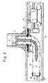
- a compressor not shown, installed on the ground is driven to supply compressed air via the air hose 19 to a closed space S, which is defined by the pressure bag 13 and the branch pipe lining assembly 1, whereby the resin-absorbent flexible member 1A of the branch pipe lining assembly 1 housed in the pressure bag 13 is everted under the pressure of the compressed air, as shown in Fig. 6, and is caused to advance upward inside the branch pipe 11 from the main pipe 10 toward the ground surface.
- the collar 1B does not budge even when it is pressed by the air pressure, and moreover since the entire body of the collar 1B is backed by the inner wall of the main pipe 10, the collar 1B is prevented from undergoing a deformation, nor does the compressed air leak at the collar 1B during the eversion of the resin-absorbent member 1A of the branch pipe lining assembly 1; consequently, the lining of the branch pipe 11 with the everted resin-absorbent member 1A of the branch pipe lining assembly 1 is performed flawlessly.
- a face of the branch pipe lining assembly 1 including the boundary portion where the outer face of the hardenable liquid resin-absorbent member 1A meets the inner circumferential face of the rigid collar 1B is hermetically sealed by the airtight polymeric film 2, as shown in detail in Fig. 2; hence, an interior face of the everted branch pipe lining assembly 1 including the boundary where the hardenable liquid resin-absorbent member 1A meets the collar 1B of the branch pipe lining assembly 1 is hermetically covered with the polymeric film 2, as shown in Fig. 7.
- a pressurized fluid such as compressed air
- the branch pipe lining assembly 1 is closely pressed against the inner walls of the branch pipe 11.
- the hardenable liquid resin-containing flexible member 1A of the branch pipe lining assembly 1 is heated by an arbitrary heating means so as to harden the thermosetting resin soaked through the flexible member 1A.
- the inner face of the branch pipe 11 is lined with the hardened branch pipe lining assembly 1, as shown in Fig. 7.
- the collar 1B of the branch pipe lining assembly 1 remains undeformed so that the pressurized fluid (compressed air) does not leak at the collar 1B, and thus the close adhesion of the flexible member 1A of the branch pipe lining assembly 1 to the inner walls of the branch pipe 11 is attained reliably.
- the collar 1B of the branch pipe lining assembly 1 does not deform, as shown in Fig. 5, so that the close adhesion of the flexible member 1A to the inner walls of the branch pipe 11 is attained assuredly.
- the main pipe liner 5 is inserted by eversion into the main pipe 10 under fluid pressure such as air pressure.
- the main pipe liner 5 consists of a tubular resin-absorbent fabric material 7 impregnated with an uncured hardenable liquid resin (thermosetting resin in this embodiment) and a highly airtight polymeric film 6, which covers up the outer face of the tubular fabric material 7.
- the tubular resin-absorbent fabric material 7 is a nonwoven fabric obtained by bonding or punch-pressing a mass of fiber such as of polyester, polypropylene, and acrylic polymer.
- the liquid resin to be absorbed in this fabric material can be selected from thermosetting resins such as unsaturated polyester, epoxy, and vinyl ester.
- the polymeric film 6 is prepared in the form of a seamless tube by the inflation method, and may be composed of a highly styrene-resistant material such as polyurethane, polyethylene, nylon, ethylene vinyl alcohol, Admer, an ionomer, and polyvinyl chloride.
- a highly styrene-resistant material such as polyurethane, polyethylene, nylon, ethylene vinyl alcohol, Admer, an ionomer, and polyvinyl chloride.
- main pipe liner 5 When the main pipe liner 5 everted and inserted into the main pipe 10 extends throughout the entire length of a unit of the main pipe 10, as shown in Fig. 9, fluid pressure is exerted inside the main pipe liner 5 so that the main pipe liner 5 is inflated and closely pressed against the inner walls of the main pipe 10. Then, while maintaining this state, the main pipe liner 5 is heated by an arbitrary heating means, so that the thermosetting resin impregnated in the main pipe liner 5 is cured to harden. Thereupon, the main pipe 10 is internally lined with the hardened main pipe liner 5, and the main pipe 10 is repaired.
- the branch pipe opening of the main pipe 10 (the opening by which the branch pipe 11 opens into the main pipe 10) is closed by the main pipe liner 5, so that it is necessary to make a hole through the main pipe liner 5 where the branch pipe 11 is closed to restore the communication between the main pipe 10 and the branch pipe 11, as shown in Fig. 10.
- an on-the-sleigh borer robot 12 is introduced inside the main pipe 10 in order to effect the boring operation on the main pipe liner 5.
- This borer robot 12 has a horizontal head rod, which is hydraulically driven to reciprocate in the axial direction as shown by a double-pointed arrow.
- a hydraulically operated motor 22 having an output shaft 22a is mounted on a head 12a supported by the head rod of the borer robot 12.
- the output shaft 22a is adapted to shift vertically as indicated by a double-pointed arrow.
- a wheel grinder 23, which has an outer diameter smaller than the diameter of the branch pipe opening, is locked about an end of the output shaft 22a of the hydraulic motor 22.
- the upper and lower side faces of the grinder 23 perpendicular to the central axis as well as the peripheral surface of rotation parallel to the central axis are made abrasive and a tapered reamer 24 is attached in the center of the upper side face.
- One pull rope 26 is tied at the front part of the sleigh of the robot 12, and another pull rope 14 is tied at the rear part of the sleigh.
- a TV camera 15 for monitoring is affixed on top of the main body of the robot 12.
- the robot 12 While its position in the main pipe 10 is being monitored by means of the TV camera 15 mounted on the robot 12 and by means of another TV camera 25 introduced in the branch pipe 11 from the ground, the robot 12 is moved to and fro in the main pipe 10 by means of the pull ropes 14 and 26 until the grinder 23 comes to a desired position for the cutting operation. Then, the hydraulically operated motor 22 is driven to spin the output shaft 22a so that the grinder 23 is turned at a high speed; at the same time the output shaft 22a is caused to rise and drop slowly so that the grinder 23 is raised and lowered.
- the tapered reamer 24 bores open a small hole in the main pipe liner 5, and then the abrasive grinder 23 bores a big hole, and through further controlling of the position of the grinder 23 by means of the various operation of the head 12a, that portion of the main pipe liner 5 which closes the branch pipe opening is ground off by the grinder 23.
- the branch pipe 11 opens into the main pipe 10 whereby the both pipes communicate with each other via this opening, as shown in Fig. 11.
- the strength of the main pipe liner 5 decreases at areas in the vicinity of the bore; however, in this embodiment, as of the completion of the lining of the main pipe 10, as shown in Fig. 9, the sum t 3 of the thickness t 1 of the collar 1B of the branch pipe lining assembly 1 and the thickness t 2 of that part of the main pipe liner 5 which overlaps the collar 1B is greater than the thickness t 4 of the other parts the main pipe liner 5 (t 1 The t 2 > t 4 ), so that the decrease in the strength of the main pipe liner 5 in the vicinity of the bore is compensated for by the presence of the collar 1B.
- the thickness t 1 of the collar 1B of the branch pipe lining assembly 1 is designed to be 25% or more of the after-compression thickness t 4 of the main pipe liner 5, and the rate of thickness decrease of that part of the main pipe liner 5 which overlaps the collar 1B is designed to be 25% lower than that of the other parts of the main pipe liner 5.
- the rate of thickness decrease of the main pipe liner 5 can be varied by adjusting the bulk density of the nonwoven fabric of which the main pipe liner 5 is made.
- the branch pipe lining assembly 1 of this embodiment of the present invention satisfies the following requirements ascribable to lining of the socket-joined branch pipe: (i) the collar 1B includes the cylindrical part 1a or the circular range 1a of protuberances, which is continuous from the hardenable resin-absorbent member 1A, and generally vertical to the planar portion of the collar 1B; (ii) the height h of the cylindrical part 1a or the circular protuberance range 1a is 0.5 - 50 mm; and (iii) the outer diameter d 2 of the cylindrical part 1a or the circular protuberance range 1a is designed to be 0.5 mm - 50 mm smaller than the inner diameter D 2 of the branch pipe 11.
- the branch pipe lining assembly 1 of this embodiment also satisfies all the requirements attributable to lining of the mortar-joined branch pipe: (i) the maximum distance d 3 between any two points which are on the outer edge of the planar portion of the collar 1B and which are opposed to each other across the center of the collar 1B is designed to be substantially greater than the outer diameter D 1 of the branch pipe 11; (ii) the thickness t 1 of the collar 1B is 1 mm or greater; (iii) the bending elasticity of the collar 1B is designed to be 30 kg/mm 2 or greater. Consequently, the branch pipe lining assembly 1 can be used for both lining the socket-joined branch pipe 11 of Fig. 5 and lining the mortar-joined branch pipe 11 of Fig. 4, and as a result, a high economical rationalization is achieved.
Landscapes
- Engineering & Computer Science (AREA)
- General Engineering & Computer Science (AREA)
- Mechanical Engineering (AREA)
- Manufacturing & Machinery (AREA)
- Lining Or Joining Of Plastics Or The Like (AREA)
- Protection Of Pipes Against Damage, Friction, And Corrosion (AREA)
Applications Claiming Priority (3)
| Application Number | Priority Date | Filing Date | Title |
|---|---|---|---|
| JP29237997 | 1997-10-24 | ||
| JP9292379A JPH11123762A (ja) | 1997-10-24 | 1997-10-24 | 枝管ライニング材及び管ライニング工法 |
| JP292379/97 | 1997-10-24 |
Publications (3)
| Publication Number | Publication Date |
|---|---|
| EP0911568A2 true EP0911568A2 (fr) | 1999-04-28 |
| EP0911568A3 EP0911568A3 (fr) | 2000-07-19 |
| EP0911568B1 EP0911568B1 (fr) | 2002-09-25 |
Family
ID=17781040
Family Applications (1)
| Application Number | Title | Priority Date | Filing Date |
|---|---|---|---|
| EP98308670A Expired - Lifetime EP0911568B1 (fr) | 1997-10-24 | 1998-10-23 | Dispositif de revêtement d'un tuyau de dérivation et procédé pour le revêtement d'un tuyau |
Country Status (5)
| Country | Link |
|---|---|
| EP (1) | EP0911568B1 (fr) |
| JP (1) | JPH11123762A (fr) |
| KR (1) | KR100547008B1 (fr) |
| DE (1) | DE69808214T2 (fr) |
| DK (1) | DK0911568T3 (fr) |
Cited By (2)
| Publication number | Priority date | Publication date | Assignee | Title |
|---|---|---|---|---|
| EP1653145A1 (fr) * | 2004-10-27 | 2006-05-03 | Shonan Gosei - Jushi Seisakusho K.K. | Methode et materiel de gainage d'une canalisation laterale |
| EP1818594A1 (fr) * | 2006-02-10 | 2007-08-15 | Per Aarsleff A/S | Réparation, rénovation ou renouvellement de conduits ou pipelines |
Families Citing this family (1)
| Publication number | Priority date | Publication date | Assignee | Title |
|---|---|---|---|---|
| AT522351B1 (de) * | 2019-10-21 | 2020-10-15 | Predl Gmbh | Schachtbodenauskleidung |
Citations (3)
| Publication number | Priority date | Publication date | Assignee | Title |
|---|---|---|---|---|
| EP0518521A2 (fr) * | 1991-05-31 | 1992-12-16 | GET Inc. | Assemblage de revêtement pour tuyaux de dérivation et méthode pour fabriquer l'assemblage de revêtement |
| EP0620102A2 (fr) * | 1993-03-23 | 1994-10-19 | Shonan Gosei - Jushi Seisakusho K.K. | Méthode de revêtement et revêtement pour tuyaux de dérivation |
| EP0752305B1 (fr) * | 1995-07-07 | 2001-05-23 | Shonan Gosei - Jushi Seisakusho K.K. | Procédé pour revêtir l'intérieur d'un tuyau coudé |
-
1997
- 1997-10-24 JP JP9292379A patent/JPH11123762A/ja active Pending
-
1998
- 1998-10-23 EP EP98308670A patent/EP0911568B1/fr not_active Expired - Lifetime
- 1998-10-23 DE DE69808214T patent/DE69808214T2/de not_active Expired - Fee Related
- 1998-10-23 DK DK98308670T patent/DK0911568T3/da active
- 1998-10-24 KR KR1019980044755A patent/KR100547008B1/ko not_active IP Right Cessation
Patent Citations (3)
| Publication number | Priority date | Publication date | Assignee | Title |
|---|---|---|---|---|
| EP0518521A2 (fr) * | 1991-05-31 | 1992-12-16 | GET Inc. | Assemblage de revêtement pour tuyaux de dérivation et méthode pour fabriquer l'assemblage de revêtement |
| EP0620102A2 (fr) * | 1993-03-23 | 1994-10-19 | Shonan Gosei - Jushi Seisakusho K.K. | Méthode de revêtement et revêtement pour tuyaux de dérivation |
| EP0752305B1 (fr) * | 1995-07-07 | 2001-05-23 | Shonan Gosei - Jushi Seisakusho K.K. | Procédé pour revêtir l'intérieur d'un tuyau coudé |
Cited By (2)
| Publication number | Priority date | Publication date | Assignee | Title |
|---|---|---|---|---|
| EP1653145A1 (fr) * | 2004-10-27 | 2006-05-03 | Shonan Gosei - Jushi Seisakusho K.K. | Methode et materiel de gainage d'une canalisation laterale |
| EP1818594A1 (fr) * | 2006-02-10 | 2007-08-15 | Per Aarsleff A/S | Réparation, rénovation ou renouvellement de conduits ou pipelines |
Also Published As
| Publication number | Publication date |
|---|---|
| KR19990037365A (ko) | 1999-05-25 |
| DE69808214D1 (de) | 2002-10-31 |
| JPH11123762A (ja) | 1999-05-11 |
| EP0911568A3 (fr) | 2000-07-19 |
| EP0911568B1 (fr) | 2002-09-25 |
| DE69808214T2 (de) | 2003-05-08 |
| DK0911568T3 (da) | 2002-11-11 |
| KR100547008B1 (ko) | 2006-04-21 |
Similar Documents
| Publication | Publication Date | Title |
|---|---|---|
| US5944058A (en) | Branch pipe liner assembly and a pipe lining method | |
| US6158473A (en) | Branch pipe liner bag and pipe lining method | |
| US6123109A (en) | Branch pipe lining bag and pipe lining method | |
| US6085794A (en) | Pipe lining method | |
| US20180010725A1 (en) | Method and Apparatus for Repairing a Pipe Junction | |
| EP0620102B1 (fr) | Méthode de revêtement et revêtement pour tuyaux de dérivation | |
| US9851040B2 (en) | Apparatus and method to repair the junction of a sewer main line and lateral pipe | |
| EP2185854B1 (fr) | Procede de reparation de conduites | |
| US7311121B2 (en) | Lateral pipe lining material and lateral pipe lining method | |
| US6056017A (en) | Pipe lining method | |
| US5916406A (en) | Branch pipe liner bag and pipe lining method | |
| US5163481A (en) | Tubular liner for softlining pipe rehabilitation | |
| EP0938964A2 (fr) | Revêtement pour une conduite de dérivation et procédé de revêtement d'une conduite de dérivation | |
| US20170146178A1 (en) | Method and Apparatus for Repairing a Pipe Junction | |
| EP0908661A2 (fr) | Chemisage d'un branchement et procédé de chemisage | |
| US20130098535A1 (en) | Method and apparatus for forming a coating on a lining of a conduit in situ | |
| EP0911568B1 (fr) | Dispositif de revêtement d'un tuyau de dérivation et procédé pour le revêtement d'un tuyau | |
| EP0891857B1 (fr) | Dispositif pour repérer la position de l'entrée d'une conduite de dérivation et méthode de revêtement de conduites utilisant ce dispositif | |
| AU2018232892A1 (en) | Device and method for repairing pipe | |
| KR19990013490A (ko) | 지관 라이닝재와 이것을 이용한 지관 라이닝공법 |
Legal Events
| Date | Code | Title | Description |
|---|---|---|---|
| PUAI | Public reference made under article 153(3) epc to a published international application that has entered the european phase |
Free format text: ORIGINAL CODE: 0009012 |
|
| AK | Designated contracting states |
Kind code of ref document: A2 Designated state(s): DE DK FR GB |
|
| AX | Request for extension of the european patent |
Free format text: AL;LT;LV;MK;RO;SI |
|
| PUAL | Search report despatched |
Free format text: ORIGINAL CODE: 0009013 |
|
| AK | Designated contracting states |
Kind code of ref document: A3 Designated state(s): AT BE CH CY DE DK ES FI FR GB GR IE IT LI LU MC NL PT SE |
|
| AX | Request for extension of the european patent |
Free format text: AL;LT;LV;MK;RO;SI |
|
| 17P | Request for examination filed |
Effective date: 20010118 |
|
| AKX | Designation fees paid |
Free format text: DE DK FR GB |
|
| 17Q | First examination report despatched |
Effective date: 20010425 |
|
| GRAG | Despatch of communication of intention to grant |
Free format text: ORIGINAL CODE: EPIDOS AGRA |
|
| GRAG | Despatch of communication of intention to grant |
Free format text: ORIGINAL CODE: EPIDOS AGRA |
|
| GRAH | Despatch of communication of intention to grant a patent |
Free format text: ORIGINAL CODE: EPIDOS IGRA |
|
| GRAH | Despatch of communication of intention to grant a patent |
Free format text: ORIGINAL CODE: EPIDOS IGRA |
|
| GRAA | (expected) grant |
Free format text: ORIGINAL CODE: 0009210 |
|
| AK | Designated contracting states |
Kind code of ref document: B1 Designated state(s): DE DK FR GB |
|
| REG | Reference to a national code |
Ref country code: GB Ref legal event code: FG4D |
|
| REF | Corresponds to: |
Ref document number: 69808214 Country of ref document: DE Date of ref document: 20021031 |
|
| REG | Reference to a national code |
Ref country code: DK Ref legal event code: T3 |
|
| ET | Fr: translation filed | ||
| PLBE | No opposition filed within time limit |
Free format text: ORIGINAL CODE: 0009261 |
|
| STAA | Information on the status of an ep patent application or granted ep patent |
Free format text: STATUS: NO OPPOSITION FILED WITHIN TIME LIMIT |
|
| 26N | No opposition filed |
Effective date: 20030626 |
|
| PGFP | Annual fee paid to national office [announced via postgrant information from national office to epo] |
Ref country code: GB Payment date: 20040122 Year of fee payment: 6 |
|
| PGFP | Annual fee paid to national office [announced via postgrant information from national office to epo] |
Ref country code: DK Payment date: 20040123 Year of fee payment: 6 |
|
| PGFP | Annual fee paid to national office [announced via postgrant information from national office to epo] |
Ref country code: FR Payment date: 20040127 Year of fee payment: 6 |
|
| PGFP | Annual fee paid to national office [announced via postgrant information from national office to epo] |
Ref country code: DE Payment date: 20040129 Year of fee payment: 6 |
|
| PG25 | Lapsed in a contracting state [announced via postgrant information from national office to epo] |
Ref country code: GB Free format text: LAPSE BECAUSE OF NON-PAYMENT OF DUE FEES Effective date: 20041023 |
|
| PG25 | Lapsed in a contracting state [announced via postgrant information from national office to epo] |
Ref country code: DK Free format text: LAPSE BECAUSE OF NON-PAYMENT OF DUE FEES Effective date: 20041101 |
|
| PG25 | Lapsed in a contracting state [announced via postgrant information from national office to epo] |
Ref country code: DE Free format text: LAPSE BECAUSE OF NON-PAYMENT OF DUE FEES Effective date: 20050503 |
|
| REG | Reference to a national code |
Ref country code: DK Ref legal event code: EBP |
|
| GBPC | Gb: european patent ceased through non-payment of renewal fee |
Effective date: 20041023 |
|
| PG25 | Lapsed in a contracting state [announced via postgrant information from national office to epo] |
Ref country code: FR Free format text: LAPSE BECAUSE OF NON-PAYMENT OF DUE FEES Effective date: 20050630 |
|
| REG | Reference to a national code |
Ref country code: FR Ref legal event code: ST |