EP0620102A2 - Méthode de revêtement et revêtement pour tuyaux de dérivation - Google Patents
Méthode de revêtement et revêtement pour tuyaux de dérivation Download PDFInfo
- Publication number
- EP0620102A2 EP0620102A2 EP94302089A EP94302089A EP0620102A2 EP 0620102 A2 EP0620102 A2 EP 0620102A2 EP 94302089 A EP94302089 A EP 94302089A EP 94302089 A EP94302089 A EP 94302089A EP 0620102 A2 EP0620102 A2 EP 0620102A2
- Authority
- EP
- European Patent Office
- Prior art keywords
- branch pipe
- bag
- flange
- liner bag
- set nozzle
- Prior art date
- Legal status (The legal status is an assumption and is not a legal conclusion. Google has not performed a legal analysis and makes no representation as to the accuracy of the status listed.)
- Granted
Links
Images


Classifications
-
- F—MECHANICAL ENGINEERING; LIGHTING; HEATING; WEAPONS; BLASTING
- F16—ENGINEERING ELEMENTS AND UNITS; GENERAL MEASURES FOR PRODUCING AND MAINTAINING EFFECTIVE FUNCTIONING OF MACHINES OR INSTALLATIONS; THERMAL INSULATION IN GENERAL
- F16L—PIPES; JOINTS OR FITTINGS FOR PIPES; SUPPORTS FOR PIPES, CABLES OR PROTECTIVE TUBING; MEANS FOR THERMAL INSULATION IN GENERAL
- F16L55/00—Devices or appurtenances for use in, or in connection with, pipes or pipe systems
- F16L55/16—Devices for covering leaks in pipes or hoses, e.g. hose-menders
- F16L55/179—Devices for covering leaks in pipes or hoses, e.g. hose-menders specially adapted for bends, branch units, branching pipes or the like
-
- B—PERFORMING OPERATIONS; TRANSPORTING
- B29—WORKING OF PLASTICS; WORKING OF SUBSTANCES IN A PLASTIC STATE IN GENERAL
- B29C—SHAPING OR JOINING OF PLASTICS; SHAPING OF MATERIAL IN A PLASTIC STATE, NOT OTHERWISE PROVIDED FOR; AFTER-TREATMENT OF THE SHAPED PRODUCTS, e.g. REPAIRING
- B29C63/00—Lining or sheathing, i.e. applying preformed layers or sheathings of plastics; Apparatus therefor
- B29C63/26—Lining or sheathing of internal surfaces
- B29C63/34—Lining or sheathing of internal surfaces using tubular layers or sheathings
- B29C63/346—Fixing the end of the lining
-
- F—MECHANICAL ENGINEERING; LIGHTING; HEATING; WEAPONS; BLASTING
- F16—ENGINEERING ELEMENTS AND UNITS; GENERAL MEASURES FOR PRODUCING AND MAINTAINING EFFECTIVE FUNCTIONING OF MACHINES OR INSTALLATIONS; THERMAL INSULATION IN GENERAL
- F16L—PIPES; JOINTS OR FITTINGS FOR PIPES; SUPPORTS FOR PIPES, CABLES OR PROTECTIVE TUBING; MEANS FOR THERMAL INSULATION IN GENERAL
- F16L55/00—Devices or appurtenances for use in, or in connection with, pipes or pipe systems
- F16L55/16—Devices for covering leaks in pipes or hoses, e.g. hose-menders
- F16L55/162—Devices for covering leaks in pipes or hoses, e.g. hose-menders from inside the pipe
- F16L55/165—Devices for covering leaks in pipes or hoses, e.g. hose-menders from inside the pipe a pipe or flexible liner being inserted in the damaged section
- F16L55/1651—Devices for covering leaks in pipes or hoses, e.g. hose-menders from inside the pipe a pipe or flexible liner being inserted in the damaged section the flexible liner being everted
Definitions
- the present invention relates to a method and for lining a pipe by applying a liner bag on the inner wall of the pipe, and in particular to a method for lining a branch pipe branching off a main pipe.
- the present invention also relates to a liner for use in such a branch pipe lining method.
- the pipe repair method comprises inserting a sufficiently long tubular flexible liner bag into the pipe to be repaired by means of a pressurized fluid, like air and water.
- the tubular liner bag is made of a flexible resin-absorbent material impregnated with a thermosetting resin, and has the outer surface covered with an impermeable plastic film.
- the tubular flexible liner bag is closed at one end and open at the other; the tubular flexible liner bag is first flattened, then, the closed end of the tubular liner bag is tied to a control rope; the open end of the tubular liner bag is made to gape wide and hooked (anchored) at the end of the defective or old pipe in a manner such that the wide-opened end of the liner completely and fixedly covers and closes the pipe end; a portion of the liner is pushed into the pipe; then, the pressurized fluid is applied to the said portion of the tubular liner such that the fluid urges the tubular liner to enter the pipe.
- the everted tubular liner is pressed against the inner wall of the pipe by the said pressurized fluid, and the tubular flexible liner is hardened as the thermosetting resin impregnated in the liner is heated, which is effected by heating the fluid filling the tubular liner bag by means of a hot steam, etc. It is thus possible to line the inside wall of the defective or old pipe with a rigid liner without digging the ground and disassembling the pipe sections.
- Fig. 7 is a cross-sectional view showing a conventional method for lining a branch pipe.
- a pressure bag 107 is inserted into a main pipe 120. Since this pressure bag 107 must be separated from a branch pipe liner bag 101, a sealed tube 111 must be connected to the pressure bag 107 for applying a pressure to the branch pipe liner bag 101.
- the sealed tube 111 and the branch pipe liner bag 101 are everted in a branch pipe 121, and the branch pipe liner bag 101 is heated to harden a hardenable resin impregnated therein while the illustrated state is held unchanged. Thereafter, when the sealed tube 111 is pulled out from the branch pipe 121 (branch pipe liner bag 101), the branch pipe has been lined by the hardened branch pipe liner bag 101. Thus, the inner wall of the branch pipe 121 is repaired.
- sealed tubes of proper lengths must be prepared depending upon variations in length of branch pipes every time a repair operation is required, wherein a problem arises that the sealed tube must be exchanged such that a suitable length is provided for a branch pipe to be repaired. Additionally, if a steeply angled bent portion is included in a branch pipe, the sealed tube may be caught by the bent portion to prevent the same from being extracted from the branch pipe.
- a work robot 206 is introduced into a main pipe 220, and a set nozzle 211 of the work robot 206 and a pressure bag 207 is connected by a guide tube 208.
- a peel-back tube 231 which enables an air-tight connection between the pressure bag 207 and the branch pipe liner bag 201. More specifically, one end of the peel-back pipe 231 is attached to the pressure bag 207, while the other end of the same is temporarily adhered to the inner wall of the branch pipe liner bag 201 such that the peel-back pipe 231 may be easily detached therefrom after the repair operation is completed.
- a flange 205 of the branch pipe liner bag 201 is positioned at a peripheral edge of an opening formed through the branch pipe 221, when a compressor, not shown, is driven to supply compressed air to the pressure bag 207 and an air mat 232, the air mat 232 is inflated as shown in Fig. 8 to cause the flange 105 of the branch pipe liner bag 201 to tightly contact with the peripheral edge of the opening in the branch pipe 221.
- the branch pipe liner bag 201 located inside the pressure bag 207, receiving the pressure of the compressed air supplied into the pressure bag 207, is gradually everted and inserted into the branch pipe 221 in the direction indicated by the white arrow in the drawing.
- a cap 233 is attached to an open end of the branch pipe liner bag 201, as shown in Fig. 9, to which an air hose 234 is connected to supply compressed air into the branch pipe liner bag 201, whereby the branch pipe liner bag 201 is pressed against the inner wall of the branch pipe 221.
- a pump 235 is driven to inject hot water stored in a tank 236 into the branch pipe liner bag 201 through a hot water hose 237
- the hot water provides heat to a thermosetting resin impregnated in the branch pipe liner bag 201 to cause the same to be cured.
- the inner wall of the branch pipe 221 is lined with the cured branch pipe liner bag 201, thus completing the repair operation of the branch pipe 221.
- this method is advantageous in that the same peel-back tube 231 may be used for branch pipes of any length; the conventionally employed sealed tube 111 (see Fig. 11) can be removed; and steeply sloped, long, or largely curved branch pipes may be efficiently lined in a similar manner.
- the temporarily adhered portion of the peel-back tube 231 may not be pealed and remain in the branch pipe liner bag 201, and the remaining portion may hinder a fluid from flowing inside the branch pipe 221.
- the present invention has been made in view of the above-mentioned problem, and its object is to provide a method for lining a branch pipe which is capable of achieving in a simple structure a direct air-tight connection between a pressure bag and a branch pipe liner bag without employing the conventionally required sealed tube.
- the present invention provides a method for lining a branch pipe branching off a main pipe comprising the steps of: (a) attaching an open end of a pressure bag to a set nozzle attached to a work robot which is movably introduced in the main pipe; (b) placing in the pressure bag a branch pipe liner bag impregnated with a thermosetting resin and having a flange at one end thereof; (c) pulling out one end of the branch pipe liner bag at the flange side from the pressure bag and everting the branch pipe liner bag; (d) removably engaging the flange with the set nozzle in concave-convex relationship; (e) supplying a pressurized fluid into the pressure bag with the flange being closely contacted to the inner wall of the main pipe around the perimeter of a branch pipe opening to evert and insert the branch pipe liner bag into the branch pipe; (f) curing the thermosetting resin impregnated in the branch pipe liner bag, the branch pipe liner bag being left pressed
- a liner for lining a branch pipe comprising: a pressure bag having an open end connected to a set nozzle coupled to a work robot placed inside a main pipe from which the branch pipe is branched off, the set nozzle having a groove on the upper surface thereof; a branch pipe liner bag impregnated with a thermosetting resin, placed inside the pressure bag; a flange coupled to one end of the branch pipe liner bag and having a protrusion on the lower surface thereof, wherein the flange is removably engaged with the set nozzle by inserting the protrusion of the flange into the groove formed in the set nozzle.
- the flange of the branch pipe liner bag is disengaged from the set nozzle to easily separate them from each other, so that the pressure bag and the work robot can be easily removed from the branch pipe liner bag. Since no peel-back tube is employed, the lining method of the present invention is free from the aforementioned problem inherent to the peel-back tube which may not be peeled favorably and partially remains inside the pipe.
- sealing members such as a packing material, an O-ring and so on in a fitting portion of the flange and the set nozzle permits a more reliable air-tight connection between the pressure bag and the branch pipe liner bag, thus allowing the branch pipe liner bag to be stably inserted in a branch pipe.
- a bonding agent if filled in the fitting portion, will further reinforce the air-tight connection.
- Fig. 1 shows a perspective view of a branch pipe liner bag used for the branch pipe lining method of the present invention, wherein part thereof is exploded for illustrating the structure thereof; and Fig. 2 is an enlarged cross-sectional view taken along a line A-A of Fig. 1.
- a branch pipe liner bag 1 shown in Fig. 1 has a tubular pipe liner bag 4 made of nonwoven fabric such as polyester, polypropylene, acrylic resin or the like, the outer surface of which is coated with highly air-tight plastic films 2 and 3 (see Fig. 2).
- the tubular pipe liner bag 4 is impregnated with a thermosetting resin.
- the plastic films 2, 3 may be made of polyurethane, polyethylene, polyethylene/nylon co-polymer, or polyvinyl chloride resin.
- the tubular pipe liner bag 4 to be inserted in the branch pipe has its tail end closed, and the front end everted outwardly to form a flange 5 which is formed in an arcuate shape with a curvature equal to that of a main pipe (see Fig. 3), later referred to.
- a protrusion 5a Over the whole inner perimeter of the lower surface of the flange 5, there is formed a protrusion 5a in a ring shape.
- the outer diameter of the branch pipe liner bag 1 is selected to be larger than the inner diameter of a branch pipe 21 (see Fig. 3), later referred to, such that the flange 5 can maintain its shape by the hardening of the thermosetting resin impregnated therein.
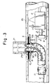
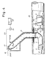
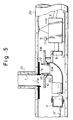
- Figs. 3 - 5 are cross-sectional views showing the branch pipe lining method in the order of processes
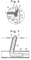
- Fig. 6 is an enlarged view of a portion B indicated in Fig. 3.
- a main pipe 20 has a branch pipe 21, branched off therefrom, which has a diameter smaller than that of the main pipe 20.
- a work robot 6 As can be seen, there have already been installed, inside the main pipe 20, a work robot 6, a pressure bag 7, the branch pipe liner bag 1 and so on which had previously been assembled and integrated on the ground.
- the work robot 6 is hydraulically driven so as to direct a head thereof 8 in the directions indicated by the arrows a and b in Fig. 3 as well as rotate the same in the direction indicated by the arrow c .
- a TV camera 9 is mounted on the work robot 6 for monitoring the movement of the head 8.
- a set nozzle 10 is supported on the head 8 of the work robot 6.
- the set nozzle 10 has a cylindrical portion 10a and a flange portion 10b.
- a concave groove 10c is formed over the entire perimeter of the surface along the outer wall of the cylindrical portion 10a. This structure is illustrated in greater detail in Fig. 6.
- the pressure bag 7 has one end thereof closed by a cap 11 and the other end forming an opening to which attached is the outer periphery of the cylinder portion 10a of the set nozzle 10, as shown in Fig. 3. Then, the pressure bag 7 is connected to a compressor installed on the ground, not shown, through an air hose 12 coupled to the cap 11.
- the aforementioned protrusion 5a protruding from the lower surface along the perimeter of the flange 5 at the end of the branch pipe liner bag 5, as shown in detail in Fig. 6, is tapered in the downward direction so as to allow the protrusion 5a to be more tightly inserted into the concave groove 10c formed in the upper surface of the set nozzle 10. Further, a ring-shaped packing material 13 and an O-ring 14 are arranged on the upper end of the cylindrical portion 10a of the set nozzle 10 and around the inner periphery of the cylindrical portion 10a near the upper end, respectively.
- the branch pipe liner bag 1 has the flange 5 thereof removably attached to the set nozzle 10 by means of the insertion of the protrusion 5a into the concave groove 10c of the set nozzle 10, while the air-tight connection between the branch pipe liner bag 1 and the pressure bag 7 is simply accomplished directly by the protrusion 5a and the concave groove 10c which are engaged in a concave-convex relationship.
- the remaining uneverted portion except for the flange 5 of the branch pipe liner bag 1 is placed inside the pressure bag 7 as shown in Fig. 3.
- the situation within the main pipe 20 may be monitored on the ground by the TV camera 9 mounted on the work robot 6.
- the head 8 of the work robot 6 is moved in the direction indicated by the arrow b in Fig. 3 (upward direction) to press the flange 5 of the branch pipe liner bag 1 against the inner wall of the main pipe 20 around the perimeter of the branch pipe opening 21a such that the flange 5 is closely contacted with the inner wall of the main pipe 20 as illustrated.
- a compressor installed on the ground, not shown, is driven to supply compressed air into the pressure bag 7 through the air hose 15 to cause the branch pipe liner bag 1, receiving the pressure of the compressed air, to be everted and go forward inside the branch pipe 21 in the direction indicated by the white arrow.
- the air-tight connection between the branch pipe liner bag 1 and the pressure bag 7 is achieved by the protrusion 5a of the flange 5 and the concave groove 10c of the set nozzle 10 which are engaged in concave-convex relationship.
- This air-tight connection may be further reinforced by a sealing effect of the packing material 13 and the O-ring 14 and moreover by a sealing effect of the bonding agent filled in the concave groove 10 (see Fig.
- a cap 17 is attached to the open end of the branch pipe liner bag 1 as shown in Fig. 4.
- Compressed air is then supplied into the branch pipe liner bag 1 from an air hose 18 connected to the cap 17 to press the branch pipe liner bag 1 against the inner wall of the branch pipe 21.
- a pump 19 is driven to inject hot water in a tank 22 into the branch pipe liner bag 1 through a hot water hose 23
- the thermosetting resin impregnated in the branch pipe liner bag 1 is heated and accordingly cured, with the result that the branch pipe 21 is repaired by means of the cured branch pipe liner 1 which has been lined on the inner wall thereof.
- the set nozzle 10 and the work robot 6 can be removed easily from the branch pipe liner bag 1. This effectively avoids the aforementioned inconvenience inherent in the prior art method that part of a peel-back tube may be left unpeeled inside the branch pipe liner bag.
- the air-tight connection between the pressure bag 7 and the branch pipe liner bag 1 is directly achieved by the protrusion 5a of the flange 5 and the concave groove 10c of the set nozzle 10 which are engaged in concave-convex relationship. Further, since the pressure bag 7 and the branch pipe liner bag 1 may be easily detached after the lining operation is completed for the branch pipe 21, a peel-back tube required by the conventional lining method is made unnecessary, with the result that the branch pipe 21 can be more easily lined.
- the open end of the pressure bag is connected to the set nozzle attached to the work robot which is movably introduced in the main pipe.
- the pressure bag is provided inside thereof with the branch pipe liner bag impregnated with a thermosetting resin and having a flange at one end.
- One end of the branch pipe liner bag on the flange side is pulled out from the pressure bag and everted.
- the flange is removably engaged with the set nozzle in concave-convex relationship such that the flange is closely contacted to the inner wall of the main pipe around the perimeter of the branch pipe opening.
- thermosetting resin impregnated in the branch pipe liner bag is cured by supplying hot water into the pressure bag. Then, after extracting the hot water from the pressure bag, the flange is disengaged from the set nozzle, and the work robot and the pressure bag are separated from the branch pipe liner bag. It will be appreciated that this method allows a direct air-tight connection between the pressure bag and the branch pipe liner bag to be made in a simple structure without employing a conventionally required sealed tube, so that the branch pipe can be more easily lined.
- thermosetting resin may be replaced by another hardenable resin such as thermosetting resin.
- thermosetting resin may be replaced by another hardenable resin such as thermosetting resin.
Landscapes
- Engineering & Computer Science (AREA)
- General Engineering & Computer Science (AREA)
- Mechanical Engineering (AREA)
- Manufacturing & Machinery (AREA)
- Lining Or Joining Of Plastics Or The Like (AREA)
- Pipe Accessories (AREA)
Applications Claiming Priority (3)
| Application Number | Priority Date | Filing Date | Title |
|---|---|---|---|
| JP63596/93 | 1993-03-23 | ||
| JP5063596A JP2530553B2 (ja) | 1993-03-23 | 1993-03-23 | 枝管ライニング工法 |
| JP6359693 | 1993-03-23 |
Publications (3)
| Publication Number | Publication Date |
|---|---|
| EP0620102A2 true EP0620102A2 (fr) | 1994-10-19 |
| EP0620102A3 EP0620102A3 (en) | 1994-11-17 |
| EP0620102B1 EP0620102B1 (fr) | 2002-01-09 |
Family
ID=13233816
Family Applications (1)
| Application Number | Title | Priority Date | Filing Date |
|---|---|---|---|
| EP94302089A Expired - Lifetime EP0620102B1 (fr) | 1993-03-23 | 1994-03-23 | Méthode de revêtement et revêtement pour tuyaux de dérivation |
Country Status (6)
| Country | Link |
|---|---|
| US (1) | US5598873A (fr) |
| EP (1) | EP0620102B1 (fr) |
| JP (1) | JP2530553B2 (fr) |
| KR (1) | KR0178140B1 (fr) |
| DE (1) | DE69429594T2 (fr) |
| DK (1) | DK0620102T3 (fr) |
Cited By (6)
| Publication number | Priority date | Publication date | Assignee | Title |
|---|---|---|---|---|
| EP0691507A1 (fr) * | 1994-07-05 | 1996-01-10 | Shonan Gosei - Jushi Seisakusho K.K. | Procédé pour revêtir une conduite latérale d'une tuyauterie enterrée |
| EP0752305A3 (fr) * | 1995-07-07 | 1997-12-10 | Shonan Gosei - Jushi Seisakusho K.K. | Procédé pour revêtir l'intérieur d'un tuyau coudé |
| WO1998046929A1 (fr) * | 1997-04-14 | 1998-10-22 | Norditubes Technologies Ab | Dispositif de reversion |
| EP0911568A3 (fr) * | 1997-10-24 | 2000-07-19 | Shonan Gosei - Jushi Seisakusho K.K. | Dispositif de revêtement d'un tuyau de dérivation et procédé pour le revêtement d'un tuyau |
| EP0938964A3 (fr) * | 1998-02-27 | 2001-01-31 | Shonan Gosei - Jushi Seisakusho K.K. | Revêtement pour une conduite de dérivation et procédé de revêtement d'une conduite de dérivation |
| KR100540897B1 (ko) * | 1997-10-06 | 2006-03-28 | 가부시키가이샤 게트 | 지관라이닝재및관라이닝공법 |
Families Citing this family (34)
| Publication number | Priority date | Publication date | Assignee | Title |
|---|---|---|---|---|
| GB9319832D0 (en) * | 1993-09-25 | 1993-11-10 | Insituform Technologies Inc | Improvements relating to the lining of pipelines and passageways |
| US5950682A (en) * | 1994-08-19 | 1999-09-14 | Lmk Enterprises, Inc. | Apparatus and method for repairing the junction of a sewer main line and lateral |
| US5916406A (en) * | 1996-02-14 | 1999-06-29 | Shonan Gosei-Jushi Seisakusho Kk | Branch pipe liner bag and pipe lining method |
| US5944058A (en) * | 1997-02-04 | 1999-08-31 | Shonan Gosei-Jushi Seisakusho K.K. | Branch pipe liner assembly and a pipe lining method |
| JPH1120021A (ja) * | 1997-07-01 | 1999-01-26 | Shonan Gosei Jushi Seisakusho:Kk | 枝管ライニング材とこれを用いた枝管ライニング工法 |
| JPH11207821A (ja) * | 1998-01-27 | 1999-08-03 | Shonan Gosei Jushi Seisakusho:Kk | 管ライニング工法 |
| JPH11227049A (ja) * | 1998-02-12 | 1999-08-24 | Shonan Gosei Jushi Seisakusho:Kk | 枝管ライニング材及び枝管ライニング工法 |
| US6039079A (en) * | 1998-07-17 | 2000-03-21 | Lmk Enterprises, Inc. | Apparatus and method for repairing the junction of a sewer main line and lateral pipe |
| JP2000052426A (ja) * | 1998-08-06 | 2000-02-22 | Shonan Gosei Jushi Seisakusho:Kk | 枝管ライニング材及び管ライニング工法 |
| CA2354226A1 (fr) | 2001-01-31 | 2002-07-31 | Cal Holland | Appareil robotique et methode d'entretien non destructif de canalisations croisees |
| US6688337B2 (en) | 2001-12-19 | 2004-02-10 | Robert M. Ward | Apparatus and method for the robotic repairing of an underground pipe junction with a flexible patch mechanism |
| US6484757B1 (en) | 2002-03-19 | 2002-11-26 | Liqui-Force Sewer Services Inc. | Method and device for lining a lateral sewer pipe |
| US20040020544A1 (en) * | 2002-04-05 | 2004-02-05 | Takao Kamiyama | Pressure bag and method of lining branch pipe |
| US6701966B1 (en) | 2003-04-22 | 2004-03-09 | Infrastructure Repair Systems, Inc. | Apparatus for lateral line repair |
| EP1519100B1 (fr) * | 2003-09-25 | 2008-11-05 | Trelleborg epros GmbH | Appareil et méthode pour la renovation de canalisations |
| JP4658562B2 (ja) * | 2004-10-08 | 2011-03-23 | タキロン株式会社 | 枝管ライニング工法並びにそれに使用する枝管ライニング装置及び枝管ライニング材 |
| TW200613677A (en) * | 2004-10-27 | 2006-05-01 | Shonan Gosei Jushi Seisakusho | Lateral pipe lining material and lateral pipe lining method |
| US7503349B2 (en) * | 2007-01-12 | 2009-03-17 | Shonan Gosei-Jushi Seisakusho K.K. | Lateral pipe lining material and lateral pipe lining method using same |
| US7845372B2 (en) * | 2007-03-30 | 2010-12-07 | Lmk Enterprises, Inc. | Bladderless pipeliner and method for using same |
| CA2628273C (fr) * | 2007-04-03 | 2014-01-07 | Darcy Warren | Doublure laterale avec joint d'etancheite |
| KR20100064333A (ko) * | 2008-12-04 | 2010-06-14 | 가부시키가이샤 쇼난 고세이쥬시 세이사쿠쇼 | 기설관 갱생 공법 및 그 공법에 사용되는 갱생관용 세그먼트 |
| US8869839B1 (en) * | 2010-03-25 | 2014-10-28 | Perma-Liner Industries, Llc | Method and device for repairing piping |
| JP2012000952A (ja) * | 2010-06-21 | 2012-01-05 | Yokoshima & Co | 管路修復方法 |
| US20120006440A1 (en) * | 2010-07-08 | 2012-01-12 | Lmk Enterprises, Inc. | Apparatus and method for lining a pipe junction |
| JP5657962B2 (ja) * | 2010-09-10 | 2015-01-21 | 株式会社湘南合成樹脂製作所 | 枝管ライニング工法及び枝管ライニング装置 |
| DE102011075403B4 (de) * | 2011-05-06 | 2014-02-13 | Trelleborg Pipe Seals Duisburg Gmbh | Kalibrierschlauch |
| JP6030937B2 (ja) * | 2012-12-07 | 2016-11-24 | 芦森工業株式会社 | 管路の内張り材、及び、管路の内張り方法 |
| DE102013010584B4 (de) * | 2013-06-26 | 2021-06-24 | I.S.T. Innovative Sewer Technologies Gmbh | Kanalsanierungsverfahren und Kanalsanierungssystem |
| US10514125B1 (en) | 2017-04-12 | 2019-12-24 | InnerCure Technologies, LLC | Underground pipe repair device with retention device and related systems and methods |
| US10309575B2 (en) | 2017-04-12 | 2019-06-04 | Inner Cure Technologies | Underground pipe repair device with radial annular spacers and related systems and methods |
| US11326732B2 (en) | 2017-04-12 | 2022-05-10 | improved Infrastructure Solutions, LLC | Underground pipe repair device with detectable annular body and related systems and methods |
| US9933105B1 (en) | 2017-04-12 | 2018-04-03 | InnerCure Technologies, LLC | Underground pipe repair device with radial stepped annular spacer and related systems and methods |
| US12442479B1 (en) * | 2021-11-05 | 2025-10-14 | improved Infrastructure Solutions, LLC | Underground pipe repair system with liner assembly and related methods |
| CN120402720B (zh) * | 2025-06-11 | 2026-03-20 | 北京市市政工程设计研究总院有限公司 | 一种地下管道堵漏机器人及工作方法 |
Family Cites Families (11)
| Publication number | Priority date | Publication date | Assignee | Title |
|---|---|---|---|---|
| GB1563424A (en) * | 1974-01-25 | 1980-03-26 | Insituform Ltd | Lining of passageways |
| GB8501474D0 (en) * | 1985-01-21 | 1985-02-20 | Edgealpha Ltd | Lining of passageways |
| GB8609307D0 (en) * | 1986-04-16 | 1986-05-21 | Insituform Group Ltd | Lining of piplines |
| JPH0677966B2 (ja) * | 1987-08-26 | 1994-10-05 | 東京瓦斯株式会社 | 管路の内張り方法 |
| US5223204A (en) * | 1990-03-06 | 1993-06-29 | Get, Inc. | Method and apparatus for reversing a tubular bag |
| GB9009073D0 (en) * | 1990-04-23 | 1990-06-20 | Insituform Group Ltd | Improvements relating to the lining of pipelines or passageways |
| JPH04185323A (ja) * | 1990-11-16 | 1992-07-02 | Mitsubishi Plastics Ind Ltd | 異種管の接続方法 |
| JP2845345B2 (ja) * | 1990-11-22 | 1999-01-13 | 東亜グラウト工業株式会社 | 管路の止水方法 |
| JP2554411B2 (ja) * | 1991-05-31 | 1996-11-13 | 株式会社ゲット | 枝管ライニング材及びその製造方法 |
| JPH0717014B2 (ja) * | 1991-07-09 | 1995-03-01 | 日本鋼管工事株式会社 | 分岐管のライニング工法 |
| US5280811A (en) * | 1991-07-18 | 1994-01-25 | Guilio Catallo | Method of softlining sewer rehabilitation |
-
1993
- 1993-03-23 JP JP5063596A patent/JP2530553B2/ja not_active Expired - Fee Related
- 1993-07-14 KR KR1019930013224A patent/KR0178140B1/ko not_active Expired - Fee Related
-
1994
- 1994-03-15 US US08/212,779 patent/US5598873A/en not_active Expired - Lifetime
- 1994-03-23 DK DK94302089T patent/DK0620102T3/da active
- 1994-03-23 DE DE69429594T patent/DE69429594T2/de not_active Expired - Fee Related
- 1994-03-23 EP EP94302089A patent/EP0620102B1/fr not_active Expired - Lifetime
Cited By (8)
| Publication number | Priority date | Publication date | Assignee | Title |
|---|---|---|---|---|
| EP0691507A1 (fr) * | 1994-07-05 | 1996-01-10 | Shonan Gosei - Jushi Seisakusho K.K. | Procédé pour revêtir une conduite latérale d'une tuyauterie enterrée |
| EP0752305A3 (fr) * | 1995-07-07 | 1997-12-10 | Shonan Gosei - Jushi Seisakusho K.K. | Procédé pour revêtir l'intérieur d'un tuyau coudé |
| AU708872B2 (en) * | 1995-07-07 | 1999-08-12 | Shonan Gosei - Jushi Seisakusho K.K. | A method for lining a bent pipe |
| WO1998046929A1 (fr) * | 1997-04-14 | 1998-10-22 | Norditubes Technologies Ab | Dispositif de reversion |
| BE1011105A3 (fr) * | 1997-04-14 | 1999-04-06 | Norditube Technologies Ab | Dispositif de reversion. |
| KR100540897B1 (ko) * | 1997-10-06 | 2006-03-28 | 가부시키가이샤 게트 | 지관라이닝재및관라이닝공법 |
| EP0911568A3 (fr) * | 1997-10-24 | 2000-07-19 | Shonan Gosei - Jushi Seisakusho K.K. | Dispositif de revêtement d'un tuyau de dérivation et procédé pour le revêtement d'un tuyau |
| EP0938964A3 (fr) * | 1998-02-27 | 2001-01-31 | Shonan Gosei - Jushi Seisakusho K.K. | Revêtement pour une conduite de dérivation et procédé de revêtement d'une conduite de dérivation |
Also Published As
| Publication number | Publication date |
|---|---|
| JP2530553B2 (ja) | 1996-09-04 |
| DK0620102T3 (da) | 2002-04-22 |
| KR0178140B1 (ko) | 1999-05-15 |
| US5598873A (en) | 1997-02-04 |
| DE69429594D1 (de) | 2002-02-14 |
| DE69429594T2 (de) | 2002-08-01 |
| EP0620102B1 (fr) | 2002-01-09 |
| EP0620102A3 (en) | 1994-11-17 |
| JPH06270253A (ja) | 1994-09-27 |
Similar Documents
| Publication | Publication Date | Title |
|---|---|---|
| US5598873A (en) | Branch pipe lining method and liner | |
| EP0650006B1 (fr) | Procédé de revêtement d'une conduite latérale | |
| EP0691507B1 (fr) | Procédé pour revêtir une conduite latérale d'une tuyauterie enterrée | |
| US7311121B2 (en) | Lateral pipe lining material and lateral pipe lining method | |
| EP0938964B1 (fr) | Revêtement pour une conduite de dérivation et procédé de revêtement d'une conduite de dérivation | |
| US5454401A (en) | Method of lining a branch pipe | |
| US5329063A (en) | Liner assembly for lining branch pipes and a method for manufacturing the liner assembly | |
| US6056017A (en) | Pipe lining method | |
| AU708872B2 (en) | A method for lining a bent pipe | |
| US5549856A (en) | Method of repairing a pipeline with an injected resin | |
| US6006787A (en) | Branch pipe liner bag and branch pipe lining method | |
| US6158473A (en) | Branch pipe liner bag and pipe lining method | |
| US6085794A (en) | Pipe lining method | |
| US20100154187A1 (en) | Pipe-lining material and pipe-lining method | |
| US5498389A (en) | Method and apparatus for lining a branch pipe | |
| US20040020544A1 (en) | Pressure bag and method of lining branch pipe | |
| EP0640464B1 (fr) | Procédé de fabrication d'un revêtement pour tuyauterie latérale | |
| JPH1120020A (ja) | 枝管ライニング材とこれを用いた枝管ライニング工法 |
Legal Events
| Date | Code | Title | Description |
|---|---|---|---|
| PUAI | Public reference made under article 153(3) epc to a published international application that has entered the european phase |
Free format text: ORIGINAL CODE: 0009012 |
|
| PUAL | Search report despatched |
Free format text: ORIGINAL CODE: 0009013 |
|
| AK | Designated contracting states |
Kind code of ref document: A2 Designated state(s): DE DK FR GB |
|
| AK | Designated contracting states |
Kind code of ref document: A3 Designated state(s): DE DK FR GB |
|
| 17P | Request for examination filed |
Effective date: 19950306 |
|
| 17Q | First examination report despatched |
Effective date: 19991013 |
|
| GRAG | Despatch of communication of intention to grant |
Free format text: ORIGINAL CODE: EPIDOS AGRA |
|
| GRAG | Despatch of communication of intention to grant |
Free format text: ORIGINAL CODE: EPIDOS AGRA |
|
| GRAH | Despatch of communication of intention to grant a patent |
Free format text: ORIGINAL CODE: EPIDOS IGRA |
|
| GRAH | Despatch of communication of intention to grant a patent |
Free format text: ORIGINAL CODE: EPIDOS IGRA |
|
| GRAA | (expected) grant |
Free format text: ORIGINAL CODE: 0009210 |
|
| REG | Reference to a national code |
Ref country code: GB Ref legal event code: IF02 |
|
| AK | Designated contracting states |
Kind code of ref document: B1 Designated state(s): DE DK FR GB |
|
| REF | Corresponds to: |
Ref document number: 69429594 Country of ref document: DE Date of ref document: 20020214 |
|
| REG | Reference to a national code |
Ref country code: DK Ref legal event code: T3 |
|
| ET | Fr: translation filed | ||
| PLBE | No opposition filed within time limit |
Free format text: ORIGINAL CODE: 0009261 |
|
| STAA | Information on the status of an ep patent application or granted ep patent |
Free format text: STATUS: NO OPPOSITION FILED WITHIN TIME LIMIT |
|
| 26N | No opposition filed | ||
| PGFP | Annual fee paid to national office [announced via postgrant information from national office to epo] |
Ref country code: DK Payment date: 20040123 Year of fee payment: 11 |
|
| PGFP | Annual fee paid to national office [announced via postgrant information from national office to epo] |
Ref country code: FR Payment date: 20040309 Year of fee payment: 11 |
|
| PGFP | Annual fee paid to national office [announced via postgrant information from national office to epo] |
Ref country code: GB Payment date: 20040317 Year of fee payment: 11 |
|
| PGFP | Annual fee paid to national office [announced via postgrant information from national office to epo] |
Ref country code: DE Payment date: 20040401 Year of fee payment: 11 |
|
| PG25 | Lapsed in a contracting state [announced via postgrant information from national office to epo] |
Ref country code: GB Free format text: LAPSE BECAUSE OF NON-PAYMENT OF DUE FEES Effective date: 20050323 |
|
| PG25 | Lapsed in a contracting state [announced via postgrant information from national office to epo] |
Ref country code: DK Free format text: LAPSE BECAUSE OF NON-PAYMENT OF DUE FEES Effective date: 20050331 |
|
| PG25 | Lapsed in a contracting state [announced via postgrant information from national office to epo] |
Ref country code: DE Free format text: LAPSE BECAUSE OF NON-PAYMENT OF DUE FEES Effective date: 20051001 |
|
| GBPC | Gb: european patent ceased through non-payment of renewal fee |
Effective date: 20050323 |
|
| PG25 | Lapsed in a contracting state [announced via postgrant information from national office to epo] |
Ref country code: FR Free format text: LAPSE BECAUSE OF NON-PAYMENT OF DUE FEES Effective date: 20051130 |
|
| REG | Reference to a national code |
Ref country code: DK Ref legal event code: EBP |
|
| REG | Reference to a national code |
Ref country code: FR Ref legal event code: ST Effective date: 20051130 |