EP0911288B1 - High speed feeder - Google Patents
High speed feeder Download PDFInfo
- Publication number
- EP0911288B1 EP0911288B1 EP98203487A EP98203487A EP0911288B1 EP 0911288 B1 EP0911288 B1 EP 0911288B1 EP 98203487 A EP98203487 A EP 98203487A EP 98203487 A EP98203487 A EP 98203487A EP 0911288 B1 EP0911288 B1 EP 0911288B1
- Authority
- EP
- European Patent Office
- Prior art keywords
- rollers
- bases
- roller
- products
- perimeter
- Prior art date
- Legal status (The legal status is an assumption and is not a legal conclusion. Google has not performed a legal analysis and makes no representation as to the accuracy of the status listed.)
- Expired - Lifetime
Links
- 238000011144 upstream manufacturing Methods 0.000 claims abstract description 8
- 238000000926 separation method Methods 0.000 claims abstract description 5
- 239000000047 product Substances 0.000 description 12
- 230000001133 acceleration Effects 0.000 description 1
- 230000000694 effects Effects 0.000 description 1
- 230000005484 gravity Effects 0.000 description 1
- 239000000463 material Substances 0.000 description 1
- 239000013589 supplement Substances 0.000 description 1
Images


Classifications
-
- B—PERFORMING OPERATIONS; TRANSPORTING
- B65—CONVEYING; PACKING; STORING; HANDLING THIN OR FILAMENTARY MATERIAL
- B65H—HANDLING THIN OR FILAMENTARY MATERIAL, e.g. SHEETS, WEBS, CABLES
- B65H3/00—Separating articles from piles
- B65H3/44—Simultaneously, alternately, or selectively separating articles from two or more piles
- B65H3/446—Simultaneously, alternately, or selectively separating articles from two or more piles alternatively, i.e. according to a fixed sequence
-
- B—PERFORMING OPERATIONS; TRANSPORTING
- B65—CONVEYING; PACKING; STORING; HANDLING THIN OR FILAMENTARY MATERIAL
- B65H—HANDLING THIN OR FILAMENTARY MATERIAL, e.g. SHEETS, WEBS, CABLES
- B65H3/00—Separating articles from piles
- B65H3/08—Separating articles from piles using pneumatic force
- B65H3/0808—Suction grippers
- B65H3/085—Suction grippers separating from the bottom of pile
- B65H3/0858—Suction grippers separating from the bottom of pile this action resulting merely in a curvature of each article being separated
- B65H3/0866—Suction grippers separating from the bottom of pile this action resulting merely in a curvature of each article being separated the final separation being performed between rollers
-
- B—PERFORMING OPERATIONS; TRANSPORTING
- B65—CONVEYING; PACKING; STORING; HANDLING THIN OR FILAMENTARY MATERIAL
- B65H—HANDLING THIN OR FILAMENTARY MATERIAL, e.g. SHEETS, WEBS, CABLES
- B65H3/00—Separating articles from piles
- B65H3/32—Separating articles from piles by elements, e.g. fingers, plates, rollers, inserted or traversed between articles to be separated and remainder of the pile
Definitions
- the present invention is directed to a device for individually feeding successive planar, flexible products from a stack thereof.
- the invention is suitable for any products falling within the foregoing category, it will be described herein with regard to the feeding of newspapers.
- a substantially horizontal support in the form of a hollow circle.
- a plurality of circumferentially spaced apart tapered rollers which extend from their bases at the perimeter of the circle radially inwardly to their inner ends.
- the taper is such that, if it were continued, it would come to a point at the center of the circle; however, the rollers are truncated short of that point.
- the bases of the rollers are mounted on a rotatable ring which is located adjacent the support.
- the bases of the tapered rollers are in contact with the stationary support. Thus, when the ring is rotated about its center, the tapered rollers are caused to rotate about their respective axes.
- At least one stack of components is placed on the rollers and the ring is caused to rotate.
- a sucker connected to a source of vacuum, moves up between an upstream roller and a following roller and pulls the leading corner of the paper down below the level of the following roller.
- the following roller enters the space between the leading comer (held down by the sucker) and the paper immediately above.
- the bottom-most paper is "peeled off" the stack and separated therefrom.
- the invention relates to a device for separation of individual planar, flexible products from a first stack thereof comprising a substantially horizontal, hollow circular support having a center and a perimeter, a plurality of circumferentially spaced apart rollers, each having a surface, extending from their bases at said perimeter radially inwardly to their inner ends, said rollers tapering radially inwardly from their bases to their inner ends and being circumferentially movable about said center in a circular direction, said first stack on some of said rollers between said bases and said inner ends, each of said products being substantially rectangular and having a first portion upstream of a second portion, a vacuum source which contacts said first portion when said first portion projects between a first roller and an adjacent second roller, said vacuum source pulling said first portion down beneath said second roller, whereby, as said rollers move in said circular direction, said second portion of said product is drawn beneath said second roller.
- said rollers have axes and rotate around said axes.
- said rollers are provided with gears at or adjacent said bases to cause rotation around said axes.
- the device comprises a stationary ring gear at said perimeter engaging said gears at or adjacent said bases, whereby relative rotation between said perimeter and said bases causes said rotation around said axes.
- said rollers are provided with frictional surfaces at or adjacent said bases to cause rotation around said axes.
- the device comprises a stationary friction element at said perimeter and contacting said frictional surfaces, whereby relative rotation between said perimeter and said bases causes said rotation around said axes.
- each of said rollers is tapered at an angle such that an extension of said surface would come to a point at said center.
- a first reduced friction bearing is on each of said inner ends within each of said holes.
- said inner ring is supported by a platform.
- said first bearing is a ball bearing.
- a first reduced friction bearing is mounted in each of said holes, said inner end being within said first friction bearing.
- said rollers are provided with gears at said inner ends.
- said rollers are axially shorter than the radius of said hollow circular support, whereby said inner ends form an inner circle concentric with said hollow circular support.
- rollers there is a second stack on some of said rollers located diametrically opposite said first stack.
- said upstream portion is a comer of said product.
- said products are folded and have folded edges, said comer is at one end of one of said folded edges.
- said edges are glued.
- the device comprises a discharge roller, a nip roller adjacent said discharge roller and separated therefrom by a gap, at least one bump on the outer surface of said discharge roller and extending only part way around a circumference of said discharge roller, said bump being located so as to nip each of said products in said gap.
- each of said products has a leading edge, said bump contacting each of said products a given distance upstream of said leading edge.
- separating device 1 comprises support 2 carrying tapered rollers 3. Bases 4 of tapered rollers 3 bear against support 2 and inner ends 5 extend radially inward. Sucker 16, connected to a source of vacuum, pulls leading comer 20 below adjacent tapered roller 3.
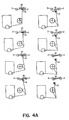
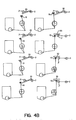
- Figure 4 shows the complete cycle of sucker 16 with relation to tapered rollers 3 and leading comer 20.
- the cycle begins at the upper left-hand comer, and proceeds down the column on the left, followed by the column immediately to the right, and so on.
- sucker 16 contacts leading corner 20 between tapered rollers 3 and 3'.
- sucker 16 As vacuum is applied to sucker 16 and it is moved downward, it carries leading comer 20 with it until it is below the level of tapered roller 3'.
- tapered roller 3' As tapered roller 3' moves to the right, it rolls on top of leading edge 20 and sucker 16 is released.
- the cycle continues as roller 3' moves further to the right and sucker 16 moves below roller 3' and then, as shown in the right hand column of Figure 4, moves up again behind roller 3' to contact the next paper at its leading comer 20.
- the paper after separation by rollers 3, falls by gravity onto feed belt 6. It is carried to, and gripped between, discharge belt 7 and guide belt 8. Since belts 7 and 8, as well as discharge roller 17, are moving faster than feed belt 6, the speed of the paper is increased. It moves around discharge roller 17 between upstream rollers 10 and downstream rollers 9 to be ejected into moving pockets (not shown) passing underneath.
- FIG. 3 A modified form of the device is shown in Figure 3.
- Newspapers 19 are delivered by feed belt 6 to nip roller 22.
- discharge roller 17 turns in the direction of arrow 18, bump 21 contacts paper 19 just behind leading edge 24.
- paper 19 is securely gripped between bump 21 and nip roller 22. Since paper 19 is accelerated at this point, bump 21 provides added insurance against slippage.
Landscapes
- Engineering & Computer Science (AREA)
- Mechanical Engineering (AREA)
- Sheets, Magazines, And Separation Thereof (AREA)
- Vending Machines For Individual Products (AREA)
- Pinball Game Machines (AREA)
- Electrical Discharge Machining, Electrochemical Machining, And Combined Machining (AREA)
- Valve Device For Special Equipments (AREA)
Applications Claiming Priority (2)
| Application Number | Priority Date | Filing Date | Title |
|---|---|---|---|
| US955734 | 1997-10-22 | ||
| US08/955,734 US6017030A (en) | 1997-10-22 | 1997-10-22 | High speed feeder |
Publications (3)
| Publication Number | Publication Date |
|---|---|
| EP0911288A2 EP0911288A2 (en) | 1999-04-28 |
| EP0911288A3 EP0911288A3 (en) | 2000-03-29 |
| EP0911288B1 true EP0911288B1 (en) | 2004-01-07 |
Family
ID=25497264
Family Applications (1)
| Application Number | Title | Priority Date | Filing Date |
|---|---|---|---|
| EP98203487A Expired - Lifetime EP0911288B1 (en) | 1997-10-22 | 1998-10-16 | High speed feeder |
Country Status (5)
| Country | Link |
|---|---|
| US (1) | US6017030A (da) |
| EP (1) | EP0911288B1 (da) |
| AT (1) | ATE257454T1 (da) |
| DE (1) | DE69820957T2 (da) |
| DK (1) | DK0911288T3 (da) |
Families Citing this family (3)
| Publication number | Priority date | Publication date | Assignee | Title |
|---|---|---|---|---|
| US6755412B1 (en) | 2002-07-23 | 2004-06-29 | Charles Dwayne Glowner | High speed overlapping insert feeding assembly |
| US7384031B2 (en) * | 2004-03-30 | 2008-06-10 | Graphic Management Associates, Inc. | Product separator and feeder |
| CN108784555B (zh) * | 2018-06-25 | 2020-11-17 | 嘉兴巨腾信息科技有限公司 | 用于地板表面的清洗设备 |
Citations (1)
| Publication number | Priority date | Publication date | Assignee | Title |
|---|---|---|---|---|
| US4383683A (en) * | 1979-10-06 | 1983-05-17 | Rahdener Maschinenfabrik August Kolbus | Apparatus for separating the bottom sheet of a stack or sheets |
Family Cites Families (11)
| Publication number | Priority date | Publication date | Assignee | Title |
|---|---|---|---|---|
| US503276A (en) * | 1893-08-15 | Sheet-feeding mechanism | ||
| US3599970A (en) * | 1969-05-23 | 1971-08-17 | Smithe Machine Co Inc F L | Apparatus for feeding blanks from the bottom of a stack |
| CH637087A5 (en) * | 1979-03-30 | 1983-07-15 | Hunkeler Jos Ag Fabrik Fuer Gr | Device for destacking one or more stacks of flexible flat structures, in particular of sheets of paper or printed products |
| GB2066787A (en) * | 1979-12-28 | 1981-07-15 | Watkiss Automation Ltd | Rotary collating machines and method of collating sheet material |
| US4369962A (en) * | 1981-02-17 | 1983-01-25 | Murray Spiro | Apparatus for feeding sheets |
| ATE19617T1 (de) * | 1981-12-24 | 1986-05-15 | Watkiss Automation Ltd | Umlaufende zusammentrag- und/oder einlegevorrichtungen und verfahren zum zusammentragen und/oder einlegen fuer blattfoermiges gut. |
| US4988086A (en) * | 1989-01-26 | 1991-01-29 | Am International Incorporated | Apparatus and method for forming sheet material assemblages |
| US4932645A (en) * | 1989-03-29 | 1990-06-12 | Am International Incorporated | Method and apparatus for controlling a multiple delivery collator in response to a downstream fault condition |
| JPH0569962A (ja) * | 1991-09-11 | 1993-03-23 | Konica Corp | 給紙装置 |
| US5213318A (en) * | 1992-01-02 | 1993-05-25 | Am International Incorporated | Signature gatherer with light detector misfeed sensors |
| DE19549675B4 (de) * | 1995-07-07 | 2005-02-17 | Windmöller & Hölscher Kg | Verfahren zum Vereinzeln gestapelter flacher Schlauchstücke |
-
1997
- 1997-10-22 US US08/955,734 patent/US6017030A/en not_active Expired - Lifetime
-
1998
- 1998-10-16 AT AT98203487T patent/ATE257454T1/de not_active IP Right Cessation
- 1998-10-16 EP EP98203487A patent/EP0911288B1/en not_active Expired - Lifetime
- 1998-10-16 DK DK98203487T patent/DK0911288T3/da active
- 1998-10-16 DE DE69820957T patent/DE69820957T2/de not_active Expired - Fee Related
Patent Citations (1)
| Publication number | Priority date | Publication date | Assignee | Title |
|---|---|---|---|---|
| US4383683A (en) * | 1979-10-06 | 1983-05-17 | Rahdener Maschinenfabrik August Kolbus | Apparatus for separating the bottom sheet of a stack or sheets |
Also Published As
| Publication number | Publication date |
|---|---|
| DK0911288T3 (da) | 2004-05-10 |
| DE69820957T2 (de) | 2004-12-09 |
| EP0911288A3 (en) | 2000-03-29 |
| ATE257454T1 (de) | 2004-01-15 |
| US6017030A (en) | 2000-01-25 |
| EP0911288A2 (en) | 1999-04-28 |
| DE69820957D1 (de) | 2004-02-12 |
Similar Documents
| Publication | Publication Date | Title |
|---|---|---|
| CA2059547C (en) | Paper sheet feeding apparatus | |
| US5083769A (en) | Dual collating machine | |
| US4871162A (en) | Sheet take-out apparatus | |
| CA2172617C (en) | Process and device for forming and moving stacks of printed sheets | |
| AU601802B2 (en) | Machines for collating forms | |
| CA2099267A1 (en) | Paper sheet feeding apparatus | |
| US5209809A (en) | Detacher to folder or pressure sealer shingle conveyor | |
| EP0911288B1 (en) | High speed feeder | |
| EP0173959B1 (en) | Sheet stacker | |
| CA2250798C (en) | Hopper loader having arced conveyor for forming an overlapping stream of signatures from a vertical stack | |
| US4260146A (en) | Process and apparatus for separating flat sheet material | |
| US5265731A (en) | Job separator | |
| CA2136670A1 (en) | Sheet length sensitive de-stacking feeder | |
| EP0703868A1 (en) | Method and apparatus for shingling documents | |
| GB2046717A (en) | Apparatus for destacking at least two stacks of flexible flat articles | |
| US6695302B1 (en) | Method and apparatus for separating a stream of spaced documents into discrete groups | |
| EP0703175B1 (en) | Apparatus and method for collating random arrays of sheets to ordered stacks | |
| JPS59102761A (ja) | 用紙処理装置 | |
| EP2107995B1 (en) | Device for separating sheets of paper by blowing air | |
| US6880818B2 (en) | Flyless stream shingling and stream merging apparatus and method | |
| JP3211042B2 (ja) | 整列搬送装置 | |
| JP3338525B2 (ja) | 重合紙片の製造装置 | |
| JP2552489B2 (ja) | 枚葉シートの集積搬出装置 | |
| JPH0620776Y2 (ja) | 用紙積載装置のディスク | |
| JPH04358661A (ja) | 屋根板状に重なる扁平な紙製品の流れを分離する装置 |
Legal Events
| Date | Code | Title | Description |
|---|---|---|---|
| PUAI | Public reference made under article 153(3) epc to a published international application that has entered the european phase |
Free format text: ORIGINAL CODE: 0009012 |
|
| AK | Designated contracting states |
Kind code of ref document: A2 Designated state(s): AT CH DE DK GB LI SE |
|
| AX | Request for extension of the european patent |
Free format text: AL;LT;LV;MK;RO;SI |
|
| PUAL | Search report despatched |
Free format text: ORIGINAL CODE: 0009013 |
|
| AK | Designated contracting states |
Kind code of ref document: A3 Designated state(s): AT BE CH CY DE DK ES FI FR GB GR IE IT LI LU MC NL PT SE |
|
| AX | Request for extension of the european patent |
Free format text: AL;LT;LV;MK;RO;SI |
|
| 17P | Request for examination filed |
Effective date: 20000929 |
|
| AKX | Designation fees paid |
Free format text: AT CH DE DK GB LI SE |
|
| 17Q | First examination report despatched |
Effective date: 20020628 |
|
| GRAH | Despatch of communication of intention to grant a patent |
Free format text: ORIGINAL CODE: EPIDOS IGRA |
|
| GRAS | Grant fee paid |
Free format text: ORIGINAL CODE: EPIDOSNIGR3 |
|
| GRAA | (expected) grant |
Free format text: ORIGINAL CODE: 0009210 |
|
| AK | Designated contracting states |
Kind code of ref document: B1 Designated state(s): AT CH DE DK GB LI SE |
|
| REG | Reference to a national code |
Ref country code: GB Ref legal event code: FG4D |
|
| REG | Reference to a national code |
Ref country code: CH Ref legal event code: EP |
|
| REG | Reference to a national code |
Ref country code: SE Ref legal event code: TRGR |
|
| REF | Corresponds to: |
Ref document number: 69820957 Country of ref document: DE Date of ref document: 20040212 Kind code of ref document: P |
|
| REG | Reference to a national code |
Ref country code: CH Ref legal event code: NV Representative=s name: BOVARD AG PATENTANWAELTE |
|
| REG | Reference to a national code |
Ref country code: DK Ref legal event code: T3 |
|
| PG25 | Lapsed in a contracting state [announced via postgrant information from national office to epo] |
Ref country code: GB Free format text: LAPSE BECAUSE OF NON-PAYMENT OF DUE FEES Effective date: 20041016 Ref country code: AT Free format text: LAPSE BECAUSE OF NON-PAYMENT OF DUE FEES Effective date: 20041016 |
|
| PG25 | Lapsed in a contracting state [announced via postgrant information from national office to epo] |
Ref country code: SE Free format text: LAPSE BECAUSE OF NON-PAYMENT OF DUE FEES Effective date: 20041017 |
|
| PG25 | Lapsed in a contracting state [announced via postgrant information from national office to epo] |
Ref country code: LI Free format text: LAPSE BECAUSE OF NON-PAYMENT OF DUE FEES Effective date: 20041031 Ref country code: CH Free format text: LAPSE BECAUSE OF NON-PAYMENT OF DUE FEES Effective date: 20041031 |
|
| PG25 | Lapsed in a contracting state [announced via postgrant information from national office to epo] |
Ref country code: DK Free format text: LAPSE BECAUSE OF NON-PAYMENT OF DUE FEES Effective date: 20041101 |
|
| PLBE | No opposition filed within time limit |
Free format text: ORIGINAL CODE: 0009261 |
|
| STAA | Information on the status of an ep patent application or granted ep patent |
Free format text: STATUS: NO OPPOSITION FILED WITHIN TIME LIMIT |
|
| 26N | No opposition filed |
Effective date: 20041008 |
|
| PG25 | Lapsed in a contracting state [announced via postgrant information from national office to epo] |
Ref country code: DE Free format text: LAPSE BECAUSE OF NON-PAYMENT OF DUE FEES Effective date: 20050503 |
|
| EUG | Se: european patent has lapsed | ||
| REG | Reference to a national code |
Ref country code: DK Ref legal event code: EBP |
|
| GBPC | Gb: european patent ceased through non-payment of renewal fee |
Effective date: 20041016 |
|
| REG | Reference to a national code |
Ref country code: CH Ref legal event code: PL |