EP0911241B2 - Contact de mise à la terre - Google Patents
Contact de mise à la terre Download PDFInfo
- Publication number
- EP0911241B2 EP0911241B2 EP98810926A EP98810926A EP0911241B2 EP 0911241 B2 EP0911241 B2 EP 0911241B2 EP 98810926 A EP98810926 A EP 98810926A EP 98810926 A EP98810926 A EP 98810926A EP 0911241 B2 EP0911241 B2 EP 0911241B2
- Authority
- EP
- European Patent Office
- Prior art keywords
- contact
- contact piece
- protective sleeve
- earthing
- brush
- Prior art date
- Legal status (The legal status is an assumption and is not a legal conclusion. Google has not performed a legal analysis and makes no representation as to the accuracy of the status listed.)
- Expired - Lifetime
Links
- 230000001681 protective effect Effects 0.000 claims abstract description 59
- 238000007789 sealing Methods 0.000 claims description 31
- 239000000314 lubricant Substances 0.000 claims description 20
- 230000035515 penetration Effects 0.000 abstract description 3
- 238000005461 lubrication Methods 0.000 abstract description 2
- 239000012530 fluid Substances 0.000 abstract 1
- OKTJSMMVPCPJKN-UHFFFAOYSA-N Carbon Chemical compound [C] OKTJSMMVPCPJKN-UHFFFAOYSA-N 0.000 description 21
- 229910052799 carbon Inorganic materials 0.000 description 21
- 230000003137 locomotive effect Effects 0.000 description 6
- 239000003082 abrasive agent Substances 0.000 description 4
- 238000011109 contamination Methods 0.000 description 4
- 239000000463 material Substances 0.000 description 4
- 239000000356 contaminant Substances 0.000 description 3
- 239000007921 spray Substances 0.000 description 3
- 230000015572 biosynthetic process Effects 0.000 description 2
- 230000007423 decrease Effects 0.000 description 2
- 239000004519 grease Substances 0.000 description 2
- 238000004519 manufacturing process Methods 0.000 description 2
- 238000005299 abrasion Methods 0.000 description 1
- 238000004378 air conditioning Methods 0.000 description 1
- 150000001875 compounds Chemical class 0.000 description 1
- 230000000694 effects Effects 0.000 description 1
- 239000002184 metal Substances 0.000 description 1
- 230000000149 penetrating effect Effects 0.000 description 1
- 239000000565 sealant Substances 0.000 description 1
Images

Classifications
-
- B—PERFORMING OPERATIONS; TRANSPORTING
- B61—RAILWAYS
- B61F—RAIL VEHICLE SUSPENSIONS, e.g. UNDERFRAMES, BOGIES OR ARRANGEMENTS OF WHEEL AXLES; RAIL VEHICLES FOR USE ON TRACKS OF DIFFERENT WIDTH; PREVENTING DERAILING OF RAIL VEHICLES; WHEEL GUARDS, OBSTRUCTION REMOVERS OR THE LIKE FOR RAIL VEHICLES
- B61F15/00—Axle-boxes
- B61F15/20—Details
- B61F15/28—Axle-boxes modified to ensure electrical conductivity
Definitions
- the present invention relates to a ground contact, which is particularly suitable for rail vehicles.
- a grounding contact is understood to mean an axle bushing or an axle bushing arrangement which ensures an electrically conductive connection between a first electrical connection and an axle or shaft rotatable relative to this first connection or a second power connection connected to this axle or shaft.
- a ground contact thus has the function of a current bridge between a stationary part and a moving part.
- a ground contact consists of a grounding stud rotatably connected to the first power connector and a contact piece rotatably connected to the second power connector, the grounding brush comprising one or more sliders (typically in the form of carbon brushes) in sliding contact with a surface (contact surface) of the contactor Contact piece are arranged to produce an electrically conductive connection between the contact piece and the grounding brush both at rest and rotating contact.
- Earthing contacts are e.g. used in electric locomotives to electrically connect the locomotive with its axles, so that the circuit from the power source (power plant or substation) via the overhead line, the pantograph, the electric motor, the locomotive, the axles, the wheels and the rails are closed back to the power source can, see eg The CH-PS-106 070.
- Earthing contacts are not only used in locomotives, but in all rail vehicles that require an electrically conductive connection between the vehicle and rails.
- a rail vehicle is to be understood as meaning any vehicle that is suitable for traveling on one or more rails, such as a rail. a railroad car for passenger and / or goods transport, a railcar, a locomotive, a dining car, a tram, a subway etc. Since today virtually all rail vehicles are provided with any power-driven facilities (eg lighting, air conditioning, public address system, etc.) are also Virtually all rail vehicles equipped with one or more ground contacts.
- the earthing contacts which in rail vehicles establish the power connection between the vehicle (or its chassis) and the axle, are always arranged in the vicinity of axle bearings, which the storage of the axle on the vehicle or on the chassis, in particular the storage of wheelsets in Bogies, serve.
- the axle bearings of rail vehicles always contain a considerable amount of grease and / or other lubricants for the purpose of lubrication. These lubricants, when they enter the region between the contact surface and the carbon brushes contacting them, can substantially hinder the electrical conductivity between the grounding brush and the contact surface. In addition, the lubricants in conjunction with abrasive material of the carbon brushes lead to the formation of lumps of material.
- axle bearings of axles equipped with ground contacts have hitherto been provided with special sealing means which prevent the leakage of lubricants from the axle bearings and thus protect the ground contacts from contamination by the lubricants. Due to the considerable dimensions of the axle bearings of rail vehicles, in particular of locomotives, and due to the high demands on the sealant in terms of durability and operability in harsh operating conditions with respect to temperature fluctuations and pollution, these seals are large, heavy and expensive to manufacture in the axle bearings.
- the object of the present invention is to provide a grounding contact which is substantially insensitive to contamination by lubricants.
- a grounding contact which is particularly suitable for a railway vehicle, comprises a grounding brush comprising an electrically conductive sliding means, which is fixed against rotation on a chassis (in the case of a rail vehicle application on a chassis of the rail vehicle) and a grounding brush rotatable contact piece, which can be rotatably attached to a chassis arranged on the wheel axle.
- the sliding means are to be arranged in electrically conductive contact with the contact piece in order to provide an electrically conductive connection between the contact piece and the grounding brush, both when the contact piece is rotating and at rest.
- the inventive Earthing contact a protective sleeve surrounding the sliding means, which prevents the ingress of lubricants in a limited by the protective sleeve, the contact piece and the grounding brush cavity.
- the protective sleeve of the grounding contact makes it possible to dispense with the sealing means required in prior art grounding contacts in the axle bearings, because the lubricant is kept away from the earth contact and thus in particular also from the abrasive material by the protective sleeve, whereby the formation of lumps mentioned at the outset Lubricants and abrasion material is prevented.
- the protective sleeve protects the grounding contact not only against the ingress of lubricants, but also against the penetration of other contaminant materials, which may affect the functionality and / or life of the grounding contact.
- the protective sleeve of the grounding contact of the invention retains the abrasive material at grounding contact formed when the slider slides or grinds on a surface of the rotating contact piece. By retaining this abrasive material through the protective sleeve, it can not contain any components located near the grounding contact, such as e.g. Axle bearing, pollute and / or obstruct.
- the sliding means of the grounding contact according to the invention comprise one or more carbon brushes; however, other suitable electrically conductive sliders may be used.
- the contact piece has a substantially flat, disk-shaped portion - a so-called contact disk - which is circular in a plane perpendicular to the axis of rotation of the contact piece (plane of rotation).
- the contact disk is rotationally fixed to be arranged on a Achsendhari a wheel axle of the rail vehicle.
- the protective sleeve of a preferred embodiment of the invention is tubular and rotatably attached to the grounding brush.
- the protective sleeve has a different shape.
- the protective sleeve is rotatably attached to the contact piece and rotates with it.
- the sealing means explained below are arranged between the protective sleeve and the grounding brush.
- sealing means are provided in the region of the axle bearings in the case of a ground contact for a rail vehicle, which retain the lubricants in the axle bearings and prevent them from penetrating into the grounding contact. Accordingly, these sealing means have a circumference which substantially corresponds to that of the axle bearings to be sealed.
- sealing means are provided between the protective sleeve and the contact piece in a preferred embodiment of the invention to effectively seal the grounding contact against the axle bearings.
- the sealing means according to this embodiment of the invention can be manufactured to a much smaller extent than the above-mentioned sealing means according to the prior art, since they no longer have to have the circumference of the axle bearings.
- the circumference of the sealing means between the protective sleeve and the contact piece is significantly smaller than the circumference of the axle bearings.
- the circumference of these sealing means measures in a plane of rotation of the contact piece or the wheel axle not even half the circumference of the axle bearings.
- the circumference of the sealing means between the protective sleeve and the contact piece in a plane of rotation of the contact piece is smaller than the circumference of the wheel axle.
- the circumference of these sealing means is even smaller than half the circumference of the wheel axle.
- An embodiment of the invention is characterized in that the sealing means between the protective sleeve and the contact piece comprise a non-contact labyrinth seal, wherein the contact piece side end edge of the protective sleeve cooperates with a correspondingly formed on the contact piece recess in sealing function.
- the sealing means comprise a differently configured labyrinth seal, a lip seal, a gap seal, a seal ring seal, or the like.
- the protective sleeve of the inventive grounding contact may have a simple circular cylindrical shape.
- the protective sleeve has a mounting flange integrated in the sleeve for fastening the sleeve to the grounding brush.
- the diameter of the tubular protective sleeve continuously decreases from the attachment point of the protective sleeve to the grounding brush towards the contact piece end of the protective sleeve.
- a preferred embodiment of the invention is further characterized in that the circumference of the protective sleeve in a plane of rotation of the contact piece is at least at the contact piece end of the protective sleeve is smaller than the circumference of the wheel axle.
- the protective sleeve is disposed relatively tightly around the slider means.
- the cross-sectional area of the protective sleeve, measured in a plane of rotation of the contact piece, is smaller than at least at the contact piece end of the protective sleeve the quadruple cross-section of the sliding means.
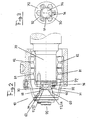
- FIG. 2 shows an embodiment of a grounding contact 10 according to the invention in a longitudinal section along a wheel axle 70 equipped with the grounding contact 10.
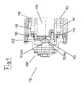
- a grounding contact 110 according to the prior art is shown in Fig. 1 in an analog view, with which a wheel axle 170 is equipped.
- the earthing contact 10 according to the invention shown in FIG. 2 consists essentially of a grounding brush 20, a contact piece 30 and a protective sleeve 40.
- the grounding brush 20 has a housing 22, which is usually made of metal and / or plastic.
- the housing 22 comprises four guide shafts open on one side, in which four elongate, columnar carbon brushes 51, 52, 53, 54 are guided in the shaft longitudinal direction with cross sections corresponding to the shaft cross-sections.
- the cross-sectional areas of the carbon brushes 51, 52, 53, 54 each measure approximately 4 cm 2 .
- the cross sections of the carbon brushes 51, 52, 53, 54 are substantially square.
- embodiments of the invention having other cross-sectional areas and other numbers of carbon brushes are also possible.
- the columnar carbon brushes 51, 52, 53, 54 project contact piece side over the shaft openings and thus the brush housing 22 also.
- the carbon brushes 51, 52, 53, 54 are pushed outward through the shaft openings by means of springs arranged in the brush housing 22 (to the right in FIGS. 2 and 5).
- the grounding brush 20 is arranged with respect to the contact piece 30 such that the carbon brushes 51, 52, 53, 54 are pressed substantially perpendicular to a contact surface 34 of the contact piece 30 to contact them in a sliding contact and a current-conducting connection between the contact piece 30th and the grounding brush 20 produce.
- the grounding brush 20 further comprises a flange 26 for fixing the grounding brush, e.g. on the chassis of a rail vehicle. Further, the grounding brush 20 is provided on the outside 24 with a power connection 25 which is electrically conductively connected to the carbon brushes 51, 52, 53, 54. To this terminal 25, e.g. connected to the electric motor or the mass of the rail vehicle power cable to establish a current bridge from the rail vehicle via the ground contact, the axle and the wheels to the railroad tracks.
- the contact piece 30 has at its end directed toward the grounding brush 20 a substantially flat, disc-shaped portion with a circular cross-section, which is referred to as a contact disk.
- the surface 34 of the contact disk facing the grounding brush 20 is referred to as the contact surface 34.
- annular recess 31 On the outer edge of an angular recess 31 along the circumference of the contact disc along the contact surface 34 is formed such that the outer edge of the contact disc is formed by a recessed in the axial direction of the contact surface 34, annular ridge 32.
- the annular recess 31 acts with the contact piece side explained below, annular end edge 42 of the protective sleeve 40 together to form together with this a labyrinth seal.
- the annular ridge 32 on the outer edge of the contact disc has essentially the function of a spray edge: as soon as grease or other lubricant, in particular from the axle bearings 81, 82, reach the contact piece 30, it is due to the centrifugal force caused by the rotating contact piece 30 to the spray edge Flung 32 and sprayed away from this from the contact piece 30.
- the grounding contact 10 has a protective sleeve 40 that relatively closely surrounds the carbon brushes 51, 52, 53, 54 and that keeps lubricants and other contaminants away from the area of the contact surface 34 and the carbon brushes 51, 52, 53, 54.
- the protective sleeve 40 is formed tubular in the embodiment of the invention shown in the figures and non-rotatably attached to the grounding brush 20 by means of a built-in sleeve 40 mounting flange 41.
- the protective sleeve 40 shown in the figures has a circular cross section, wherein the diameter of the protective sleeve 40 from the mounting flange 41 to the contact piece side end edge 42 of the protective sleeve 40 decreases continuously.
- the diameter of the circular protective sleeve 40 at the contact piece side end edge 42 measures approximately 8 cm, with the square cross section arrangement of the carbon brushes 51, 52, 53, 54 having an edge length of approximately 4.4 cm.
- the carbon brushes 51,52,53,54 are thus relatively tightly enclosed by the protective sleeve. From Fig. 2 it is further apparent that the circumference of the protective sleeve 40 in a plane of rotation of the contact piece 30 is substantially smaller than the circumference of the wheel axle 70 and the circumference of the axle bearings 81, 82nd
- sealing means 31, 42 are provided between the protective sleeve 40 and the contact piece 30.
- the annular end edge 42 of the protective sleeve 40 with respect to the annular recess 31 of the contact disc is arranged such that the arrangement a total of a labyrinth seal 31, 42 forms.
- the gap between the end edge 42 of the protective sleeve 40 and the contact disc measures only about 1 mm.
- the labyrinth seal 31, 42 in conjunction with the annular ridge 32 of the contact piece 30 acting as a spray edge, ensures reliable, non-contact sealing of the cavity 60.
- Fig. 1 for comparison equipped with a grounding contact 110 according to the prior art wheel axle 170 is shown.
- the grounding brush 120 with the carbon brushes 151, 152, 153, 154 of the grounding contact 110 substantially coincides in terms of their shape and function with the grounding brush 20 with the carbon brushes 51, 52, 53, 54 of the inventive grounding contact 10.
- the contact piece 30 and the axle bearings 81, 82 in the grounding contact 10 according to the invention correspond to the contact piece 130 and the axle bearings 181, 182 of the known grounding contact 110.
- the invention provides a ground contact which is substantially insensitive to contamination by lubricants.
- an embodiment of the inventive grounding contact is also distinguished by sealing means for sealing the grounding contact, in particular with respect to axle bearings, which are much more compact, lighter and less expensive than the corresponding sealing means in the axleboxes for earthing contacts according to the prior art.
Landscapes
- Engineering & Computer Science (AREA)
- Mechanical Engineering (AREA)
- Elimination Of Static Electricity (AREA)
- Current-Collector Devices For Electrically Propelled Vehicles (AREA)
- Contacts (AREA)
- Coupling Device And Connection With Printed Circuit (AREA)
Claims (10)
- Contact de mise à la terre (10), notamment pour un véhicule sur rails, doté d'un balai de mise à la terre (20), comportant des organes de glissement (50, 51, 52, 53) électroconducteurs, à disposer de façon rigide en rotation, sur un châssis et dote d'un plot de contact (30) mobile en rotation relativement au balai de mise à la terre (20) avec une surface (34) arrangée vers à la mise à la terre (20), dans lequel les organes de glissement (50, 51, 52, 53) sont placés en contact électroconducteur avec la surface (34) du plot de contact (30) de façon à mettre une liaison électroconductrice à disposition entre le plot de contact (30) et le balai de mise à la terre (20), dans le cas où le plot de contact (30) est en rotation comme dans le cas où il est immobile, et avec une douille de protection (40) entourant tubulairement les organes de glissement (50, 51, 52, 53) servant à éviter que les lubrifiants ne pénètrent, caractérise en ce que la douille de protection (40) agit avec un bord extérieur de la surface (34) du plot de contact (30) afin d'étancher et d'éviter que les lubrifiants ne pénètrent dans un espace (60) délimité par la douille de protection (40), le plot de contact (30) et le balai de mise à la terre (20).
- Contact de mise à la terre (10) selon la revendication 1, caractérisé en ce que le plot de contact (30) présente une partie essentiellement plane en forme de disque avec une section circulaire (disque de contact), dans lequel le plot de contact est à agencer, de façon rigide en rotation, sur un disque d'essieu (72) d'un essieu (70) monté sur le châssis.
- Contact de mise à la terre (10) selon l'une quelconque des revendications 1 ou 2, caractérisé en ce que la douille de protection (40) est essentiellement tubulaire et en ce qu'elle est fixée, de façon rigide en rotation, sur le balai de mise à la terre (20).
- Contact de mise à la terre (10) selon l'une quelconque des revendications1 à 3, caractérisé par des organes d'étanchéité (31, 42) à disposer entre la douille de protection (40) et le plot de contact (30) servant à éviter que les lubrifiants ne pénètrent dans l'espace (60) délimité par la douille de protection (40), le plot de contact (30) et le balai de mise à la terre (20).
- Contact de mise à la terre (10) selon la revendication 4, caractérisé en ce que les organes d'étanchéité (31, 42) comportent, entre la douille de protection (40) et le plot de contact (30), une garniture en labyrinthe sans contact (31, 42) dans laquelle le bord en bout (42) de la douille de protection (40), du côté du plot de contact, et un creux (31) formé de façon adéquate sur le plot de contact (30), assurent conjointement une fonction d'étanchéité.
- Contact de mise à la terre (10) selon la revendication 2 et selon l'une quelconque des revendications 4 ou 5, caractérisé en ce que la circonférence des organes d'étanchéité (31, 42) entre la douille de protection (40) et le plot de contact (30) dans un plan de rotation du plot de contact (30) est inférieure à la circonférence des boîtes d'essieu (81, 82) qui servent au montage de l'essieu (70).
- Contact de mise à la terre (10) selon la revendication 6, caractérisé en ce que la circonférence des organes d'étanchéité (31, 42) entre la douille de protection (40) et le plot de contact (30) dans un plan de rotation du plot de contact (30) est inférieure à la circonférence de l'essieu (70).
- Contact de mise à la terre (10) selon l'une quelconque des revendications 2 à 7, caractérisé en ce que la circonférence de la douille de protection (40) dans un plan de rotation du plot de contact (30) est, au moins au niveau de l'extrémité (42) de la douille de protection (40) du côté du plot de contact, inférieure à la circonférence de l'essieu (70).
- Contact de mise à la terre (10) selon l'une quelconque des revendications1 à 8, caractérisé en ce que la section de la douille de protection (40) dans un plan de rotation du plot de contact (30) est, au moins au niveau de son extrémité (42) du côté du plot de contact, inférieure à quatre fois la section des organes de glissement (50, 51, 52, 53).
- Véhicule sur rails avec contact de mise à la terre (10) selon l'une quelconque des revendications 1 à 9, caractérisé en ce que le contact de mise à la terre (10) présente, d'une part, un balai de mise à la terre (20) agencé de façon rigide en rotation, sur le châssis du véhicule sur rails et comportant des organes de glissement électroconducteurs (50, 51, 52, 53) et, d'autre part, un plot de contact (30) mobile en rotation relativement au balai de mise à la terre (20), dans lequel les organes de glissement (50, 51, 52, 53) sont placés en contact électroconducteur avec le plot de contact (30) de façon à mettre une liaison électroconductrice à disposition entre le plot de contact (30) et le balai de mise à la terre (20), dans le cas où le plot de contact (30) est en rotation comme dans le cas où il est immobile, ainsi qu'une douille de protection (40) entourant les organes de glissement (50, 51, 52, 53) servant à éviter que les lubrifiants ne pénètrent dans un espace (60) délimité par la douille de protection (40), le plot de contact (30) et le balai de mise à la terre (20).
Applications Claiming Priority (3)
| Application Number | Priority Date | Filing Date | Title |
|---|---|---|---|
| CH2454/97 | 1997-10-22 | ||
| CH245497 | 1997-10-22 | ||
| CH245497 | 1997-10-22 |
Publications (3)
| Publication Number | Publication Date |
|---|---|
| EP0911241A1 EP0911241A1 (fr) | 1999-04-28 |
| EP0911241B1 EP0911241B1 (fr) | 2003-03-05 |
| EP0911241B2 true EP0911241B2 (fr) | 2007-02-21 |
Family
ID=4234199
Family Applications (1)
| Application Number | Title | Priority Date | Filing Date |
|---|---|---|---|
| EP98810926A Expired - Lifetime EP0911241B2 (fr) | 1997-10-22 | 1998-09-17 | Contact de mise à la terre |
Country Status (3)
| Country | Link |
|---|---|
| EP (1) | EP0911241B2 (fr) |
| AT (1) | ATE233686T1 (fr) |
| DE (1) | DE59807370D1 (fr) |
Families Citing this family (2)
| Publication number | Priority date | Publication date | Assignee | Title |
|---|---|---|---|---|
| DE10256975A1 (de) * | 2002-12-05 | 2004-06-24 | Siemens Ag | Vorrichtung zum Erden eines Eisenbahnfahrzeugs |
| DE102010039847A1 (de) * | 2010-08-26 | 2012-03-01 | Schunk Bahn- Und Industrietechnik Gmbh | Erdungskontakt |
Family Cites Families (2)
| Publication number | Priority date | Publication date | Assignee | Title |
|---|---|---|---|---|
| CH106070A (de) * | 1923-08-13 | 1924-08-01 | Kugellagerwerke J Schmid Roost | Stromrückleitungseinrichtung an elektrischen Bahnmotorwagen mit Kugel- oder Rollenlagern. |
| DE19654339B4 (de) * | 1996-12-24 | 2004-12-02 | G. Dietrich Gmbh | Erdungskontakteinrichtung |
-
1998
- 1998-09-17 DE DE59807370T patent/DE59807370D1/de not_active Expired - Lifetime
- 1998-09-17 EP EP98810926A patent/EP0911241B2/fr not_active Expired - Lifetime
- 1998-09-17 AT AT98810926T patent/ATE233686T1/de not_active IP Right Cessation
Non-Patent Citations (15)
| Title |
|---|
| Bestellung der Fa. ABB vom 13.11.1996 † |
| Bestellung der Fa. ABB vom 17.04.1996 † |
| Bestellung Fa. Siemens vom 01.06.1993 † |
| CAD-Zeichnung 245.1780-2, farbig angelegt † |
| Gegenüberstellung drehender und stehender Teile des Erdungskontaktes gem. Zeichnung 245.1769-2 † |
| Handelsregisterauszug HRB 742 † |
| Lieferschein Fa. Stemmann vom 08.09.1993 † |
| Rechnung der Fa. Stemmann vom 12.08.1996 † |
| Rechnung der Fa. Stemmann vom 27.01.1997 † |
| Rechnung Fa. Stemmann vom 08.09.1993 † |
| Ursprungszeichnung 245.1780-2 im Format DIN A2 † |
| verkleinerte Zeichnung 245.1769-2 mit Bezugszeichen der EP-B1 in Rot † |
| Versandanzeige/ Leiferschein der Fa. Stemmann vom 12.08.1996 † |
| Versandanzeige/ Lieferschein der Fa. Stemmann vom 27.01.1997 † |
| Zeichnung 245.1769-2 (DIN A 2) † |
Also Published As
| Publication number | Publication date |
|---|---|
| EP0911241B1 (fr) | 2003-03-05 |
| DE59807370D1 (de) | 2003-04-10 |
| EP0911241A1 (fr) | 1999-04-28 |
| ATE233686T1 (de) | 2003-03-15 |
Similar Documents
| Publication | Publication Date | Title |
|---|---|---|
| DE1575437B1 (de) | Kugelgelenk, insbesondere zur Verwen dung bei Kraftfahrzeugen | |
| EP0487891A1 (fr) | Palier coulissant élastique | |
| WO1992004563A1 (fr) | Dispositif d'entrainement, notamment d'essuie-glaces de vehicules a moteur | |
| EP3820798A1 (fr) | Système de transport et dispositif de transport | |
| AT405390B (de) | Elektromotorischer radnabenantrieb für ein fahrzeugrad | |
| DE102007049906A1 (de) | Übertragungselement, insbesondere Riemenscheibe oder Rolle für einen Zugmitteltrieb | |
| DE10045422A1 (de) | Drehgelenkanordnung und Verfahren zum Erstellen derselben | |
| WO2009010185A1 (fr) | Dispositif de palier pour des arbres à excentrique | |
| EP0911241B2 (fr) | Contact de mise à la terre | |
| EP1136340B1 (fr) | Contact de mise à la terre | |
| EP0469329B1 (fr) | Ensemble de pédalier pour bicyclettes | |
| EP3924283B1 (fr) | Système d'ascenseur avec liaison à la terre de la cabine | |
| DE102021214533A1 (de) | Anordnung zur Erdung einer Welle | |
| DE10012739B4 (de) | Erdungskontakt sowie Verfahren zur Herstellung eines Gleitkörpers wie einer Kontaktscheibe eines Erdungskontaktes | |
| EP1065122B1 (fr) | Essieu de roue folle pour véhicules ferroviaires | |
| DE19920384C1 (de) | Erdungskontakt | |
| DE9205662U1 (de) | Rollenanordnung für Raupenkette | |
| DE4223243A1 (de) | Geerdete Radlagerung eines Schienenfahrzeuges | |
| DE102013223549A1 (de) | Achsschenkellenkeinrichtung eines Fahrzeugs | |
| DE102005054113B4 (de) | Anlaufscheibe | |
| DE9205688U1 (de) | Erdungskontakt | |
| EP0864472B1 (fr) | Dispositif d'entraínement, en particulier pour essuie-glace de véhicule automobile | |
| DE7302217U (de) | Lager für Kreuzgelenkzapfen | |
| DE3942401A1 (de) | Selbstschmierendes kipplager mit innendichtung | |
| DE2204848C3 (de) | Belüftungsanordnung für Drehgestell-Fahrmotoren eines elektrischen Schienentriebfahrzeuges |
Legal Events
| Date | Code | Title | Description |
|---|---|---|---|
| PUAI | Public reference made under article 153(3) epc to a published international application that has entered the european phase |
Free format text: ORIGINAL CODE: 0009012 |
|
| AK | Designated contracting states |
Kind code of ref document: A1 Designated state(s): AT BE CH DE FR GB IE IT LI NL SE |
|
| AX | Request for extension of the european patent |
Free format text: AL;LT;LV;MK;RO;SI |
|
| 17P | Request for examination filed |
Effective date: 19991006 |
|
| AKX | Designation fees paid |
Free format text: AT BE CH DE FR GB IE IT LI NL SE |
|
| GRAH | Despatch of communication of intention to grant a patent |
Free format text: ORIGINAL CODE: EPIDOS IGRA |
|
| GRAH | Despatch of communication of intention to grant a patent |
Free format text: ORIGINAL CODE: EPIDOS IGRA |
|
| GRAA | (expected) grant |
Free format text: ORIGINAL CODE: 0009210 |
|
| AK | Designated contracting states |
Designated state(s): AT BE CH DE FR GB IE IT LI NL SE |
|
| PG25 | Lapsed in a contracting state [announced via postgrant information from national office to epo] |
Ref country code: NL Free format text: LAPSE BECAUSE OF FAILURE TO SUBMIT A TRANSLATION OF THE DESCRIPTION OR TO PAY THE FEE WITHIN THE PRESCRIBED TIME-LIMIT Effective date: 20030305 Ref country code: IE Free format text: LAPSE BECAUSE OF FAILURE TO SUBMIT A TRANSLATION OF THE DESCRIPTION OR TO PAY THE FEE WITHIN THE PRESCRIBED TIME-LIMIT Effective date: 20030305 |
|
| REG | Reference to a national code |
Ref country code: GB Ref legal event code: FG4D Free format text: NOT ENGLISH |
|
| REG | Reference to a national code |
Ref country code: CH Ref legal event code: NV Representative=s name: KELLER & PARTNER PATENTANWAELTE AG Ref country code: CH Ref legal event code: EP |
|
| REG | Reference to a national code |
Ref country code: IE Ref legal event code: FG4D Free format text: GERMAN |
|
| REF | Corresponds to: |
Ref document number: 59807370 Country of ref document: DE Date of ref document: 20030410 Kind code of ref document: P |
|
| RAP2 | Party data changed (patent owner data changed or rights of a patent transferred) |
Owner name: TIBRAM AG |
|
| PG25 | Lapsed in a contracting state [announced via postgrant information from national office to epo] |
Ref country code: SE Free format text: LAPSE BECAUSE OF FAILURE TO SUBMIT A TRANSLATION OF THE DESCRIPTION OR TO PAY THE FEE WITHIN THE PRESCRIBED TIME-LIMIT Effective date: 20030605 |
|
| GBT | Gb: translation of ep patent filed (gb section 77(6)(a)/1977) | ||
| NLT2 | Nl: modifications (of names), taken from the european patent patent bulletin |
Owner name: TIBRAM AG |
|
| NLV1 | Nl: lapsed or annulled due to failure to fulfill the requirements of art. 29p and 29m of the patents act | ||
| PLBQ | Unpublished change to opponent data |
Free format text: ORIGINAL CODE: EPIDOS OPPO |
|
| PLBI | Opposition filed |
Free format text: ORIGINAL CODE: 0009260 |
|
| PG25 | Lapsed in a contracting state [announced via postgrant information from national office to epo] |
Ref country code: AT Free format text: LAPSE BECAUSE OF NON-PAYMENT OF DUE FEES Effective date: 20030917 |
|
| ET | Fr: translation filed | ||
| 26 | Opposition filed |
Opponent name: STEMMANN-TECHNIK GMBH Effective date: 20030827 |
|
| REG | Reference to a national code |
Ref country code: IE Ref legal event code: FD4D Ref document number: 0911241E Country of ref document: IE |
|
| PLAX | Notice of opposition and request to file observation + time limit sent |
Free format text: ORIGINAL CODE: EPIDOSNOBS2 |
|
| PLBB | Reply of patent proprietor to notice(s) of opposition received |
Free format text: ORIGINAL CODE: EPIDOSNOBS3 |
|
| PLAY | Examination report in opposition despatched + time limit |
Free format text: ORIGINAL CODE: EPIDOSNORE2 |
|
| PLAH | Information related to despatch of examination report in opposition + time limit modified |
Free format text: ORIGINAL CODE: EPIDOSCORE2 |
|
| PLBC | Reply to examination report in opposition received |
Free format text: ORIGINAL CODE: EPIDOSNORE3 |
|
| PLAB | Opposition data, opponent's data or that of the opponent's representative modified |
Free format text: ORIGINAL CODE: 0009299OPPO |
|
| R26 | Opposition filed (corrected) |
Opponent name: STEMMANN-TECHNIK GMBH Effective date: 20030827 |
|
| PUAH | Patent maintained in amended form |
Free format text: ORIGINAL CODE: 0009272 |
|
| STAA | Information on the status of an ep patent application or granted ep patent |
Free format text: STATUS: PATENT MAINTAINED AS AMENDED |
|
| 27A | Patent maintained in amended form |
Effective date: 20070221 |
|
| AK | Designated contracting states |
Kind code of ref document: B2 Designated state(s): AT BE CH DE FR GB IE IT LI NL SE |
|
| REG | Reference to a national code |
Ref country code: CH Ref legal event code: AEN Free format text: AUFRECHTERHALTUNG DES PATENTES IN GEAENDERTER FORM |
|
| GBTA | Gb: translation of amended ep patent filed (gb section 77(6)(b)/1977) | ||
| ET3 | Fr: translation filed ** decision concerning opposition | ||
| PG25 | Lapsed in a contracting state [announced via postgrant information from national office to epo] |
Ref country code: IT Free format text: LAPSE BECAUSE OF NON-PAYMENT OF DUE FEES Effective date: 20070917 |
|
| PGFP | Annual fee paid to national office [announced via postgrant information from national office to epo] |
Ref country code: GB Payment date: 20100903 Year of fee payment: 13 |
|
| PGFP | Annual fee paid to national office [announced via postgrant information from national office to epo] |
Ref country code: IT Payment date: 20100930 Year of fee payment: 13 |
|
| PGRI | Patent reinstated in contracting state [announced from national office to epo] |
Ref country code: IT Effective date: 20110616 |
|
| PGFP | Annual fee paid to national office [announced via postgrant information from national office to epo] |
Ref country code: CH Payment date: 20110913 Year of fee payment: 14 |
|
| GBPC | Gb: european patent ceased through non-payment of renewal fee |
Effective date: 20110917 |
|
| PG25 | Lapsed in a contracting state [announced via postgrant information from national office to epo] |
Ref country code: IT Free format text: LAPSE BECAUSE OF NON-PAYMENT OF DUE FEES Effective date: 20110917 |
|
| PG25 | Lapsed in a contracting state [announced via postgrant information from national office to epo] |
Ref country code: GB Free format text: LAPSE BECAUSE OF NON-PAYMENT OF DUE FEES Effective date: 20110917 |
|
| PGFP | Annual fee paid to national office [announced via postgrant information from national office to epo] |
Ref country code: DE Payment date: 20120914 Year of fee payment: 15 |
|
| PGFP | Annual fee paid to national office [announced via postgrant information from national office to epo] |
Ref country code: BE Payment date: 20120926 Year of fee payment: 15 |
|
| PGFP | Annual fee paid to national office [announced via postgrant information from national office to epo] |
Ref country code: FR Payment date: 20130829 Year of fee payment: 16 |
|
| BERE | Be: lapsed |
Owner name: *TIBRAM A.G. Effective date: 20130930 |
|
| REG | Reference to a national code |
Ref country code: CH Ref legal event code: PL |
|
| REG | Reference to a national code |
Ref country code: DE Ref legal event code: R119 Ref document number: 59807370 Country of ref document: DE Effective date: 20140401 |
|
| PG25 | Lapsed in a contracting state [announced via postgrant information from national office to epo] |
Ref country code: CH Free format text: LAPSE BECAUSE OF NON-PAYMENT OF DUE FEES Effective date: 20130930 Ref country code: LI Free format text: LAPSE BECAUSE OF NON-PAYMENT OF DUE FEES Effective date: 20130930 Ref country code: BE Free format text: LAPSE BECAUSE OF NON-PAYMENT OF DUE FEES Effective date: 20130930 |
|
| PG25 | Lapsed in a contracting state [announced via postgrant information from national office to epo] |
Ref country code: DE Free format text: LAPSE BECAUSE OF NON-PAYMENT OF DUE FEES Effective date: 20140401 |
|
| REG | Reference to a national code |
Ref country code: FR Ref legal event code: ST Effective date: 20150529 |
|
| PG25 | Lapsed in a contracting state [announced via postgrant information from national office to epo] |
Ref country code: FR Free format text: LAPSE BECAUSE OF NON-PAYMENT OF DUE FEES Effective date: 20140930 |