EP0911239B1 - Bogie with one or more axles for a low-floor vehicle - Google Patents
Bogie with one or more axles for a low-floor vehicle Download PDFInfo
- Publication number
- EP0911239B1 EP0911239B1 EP19980402637 EP98402637A EP0911239B1 EP 0911239 B1 EP0911239 B1 EP 0911239B1 EP 19980402637 EP19980402637 EP 19980402637 EP 98402637 A EP98402637 A EP 98402637A EP 0911239 B1 EP0911239 B1 EP 0911239B1
- Authority
- EP
- European Patent Office
- Prior art keywords
- bogie
- axle
- axles
- motor
- bogie according
- Prior art date
- Legal status (The legal status is an assumption and is not a legal conclusion. Google has not performed a legal analysis and makes no representation as to the accuracy of the status listed.)
- Expired - Lifetime
Links
Images


Classifications
-
- B—PERFORMING OPERATIONS; TRANSPORTING
- B61—RAILWAYS
- B61F—RAIL VEHICLE SUSPENSIONS, e.g. UNDERFRAMES, BOGIES OR ARRANGEMENTS OF WHEEL AXLES; RAIL VEHICLES FOR USE ON TRACKS OF DIFFERENT WIDTH; PREVENTING DERAILING OF RAIL VEHICLES; WHEEL GUARDS, OBSTRUCTION REMOVERS OR THE LIKE FOR RAIL VEHICLES
- B61F3/00—Types of bogies
- B61F3/02—Types of bogies with more than one axle
- B61F3/04—Types of bogies with more than one axle with driven axles or wheels
-
- B—PERFORMING OPERATIONS; TRANSPORTING
- B61—RAILWAYS
- B61C—LOCOMOTIVES; MOTOR RAILCARS
- B61C9/00—Locomotives or motor railcars characterised by the type of transmission system used; Transmission systems specially adapted for locomotives or motor railcars
- B61C9/38—Transmission systems in or for locomotives or motor railcars with electric motor propulsion
- B61C9/48—Transmission systems in or for locomotives or motor railcars with electric motor propulsion with motors supported on vehicle frames and driving axles, e.g. axle or nose suspension
- B61C9/50—Transmission systems in or for locomotives or motor railcars with electric motor propulsion with motors supported on vehicle frames and driving axles, e.g. axle or nose suspension in bogies
-
- B—PERFORMING OPERATIONS; TRANSPORTING
- B61—RAILWAYS
- B61F—RAIL VEHICLE SUSPENSIONS, e.g. UNDERFRAMES, BOGIES OR ARRANGEMENTS OF WHEEL AXLES; RAIL VEHICLES FOR USE ON TRACKS OF DIFFERENT WIDTH; PREVENTING DERAILING OF RAIL VEHICLES; WHEEL GUARDS, OBSTRUCTION REMOVERS OR THE LIKE FOR RAIL VEHICLES
- B61F3/00—Types of bogies
- B61F3/16—Types of bogies with a separate axle for each wheel
Definitions
- the present invention relates to a bogie comprising one or more several axles intended to equip a vehicle of the type with integral "low floor".
- the passenger floor is typically about 350 mm above the rail level.
- the low-floor vehicle is for example a vehicle tram type railroad.
- DE-A1-44 19 362 discloses a motor bogie by rail wire for low-floor vehicle comprising a axle consisting of a load-bearing beam and receiving hubs carrying wheels.
- the first architecture has the advantage, thanks presence of one motor per wheel, to have wheels independent in rotation which facilitate registration in bogie curve.
- the first architecture has the major drawback generate a high cost of the motorization function (electrical equipment for motors, reducers ⁇ .
- the first architecture also presents the disadvantage of not allowing to benefit from the principle mechanical self-stabilization of the railway axle brought by the taper of the wheel treads wedged on the same tree.
- the second architecture has the major drawback too long overall axle dimensions to obtain a vehicle with an integral low floor.
- the second architecture presents the disadvantage of not allowing positioning, in the body and to the right of the bogie, typically sixteen seats in the direction of travel, due to the longitudinal arrangement motors above the rails.
- the second architecture also presents the disadvantage of not allowing either to benefit from the principle of mechanical self-stabilization of the axle railway brought by the conicity of the tread tables wheels wedged on the same tree.
- the third architecture has the disadvantage of do not allow to have, in the box and the four bogie corners, access doors, due to layout of the engine outside the bogie and therefore under the body.
- the third architecture also presents the disadvantage of not allowing a bogie to be produced fully motorized because it is necessary to install at least two access doors in the box near the bogie.
- the transmission device of the movement of the motor to the wheels by rotating axle is placed too high to allow a floor vehicle to be obtained low.
- an object of the invention is a bogie comprising one or more axles intended to equip a vehicle of the type with low integral floor, without the disadvantages bogies of the prior art and having a space requirement reduced overall longitudinal axle to allow a vehicle with an integral low floor.
- the bogie comprising one or more axles intended for equipping a vehicle of the type with a full low floor is such as characterized below.
- each wheel is driven by a motor-reduction unit attached to the wheel.
- the four wheels are then independent in rotation.
- each motor drives through two reducers two wheels located on the same side of the bogie.
- the two wheels on the same side are therefore linked in rotation but there is independence in rotation of the wheels of the right line of the bogie with the wheels of the left yarn.
- the motor drives via a shaft of cardan type a bevel gear pair housed in a reduction gear placed near one of the two wheels. Conical couple the movement is sent to one of the wheels directly by a flat gear train and on the second wheel by a second plane gear train identical to the previous one but via a connecting shaft located sufficiently low to allow a vehicle floor, for example at 350 mm above the level of the rail.
- the axle motor drives a double gear train.
- the engine drives a first stage from which the movement is distributed, via a second stage, directly on the wheel on the motor side and via a shaft transmission (passing under the lower part of the floor of body, for example 350mm) on the wheel opposite the engine.
- the two axles are connected to each other by two spars, one of the ends of each of which is rigidly attached to one of the axles and the other end is attached to the other axle via a elastic joint whose role is to allow the bogie to absorb the track lefts.
- Figures 5 to 8 show an axle conforming to the invention in a configuration with one axle motor.
- Table 1 shows the different configurations possible provided by the axle according to the invention.
- Table 2 shows the different configurations possible bogies created from two axles according to the invention.
- the vehicle body Cv rests on the gantry-shaped bridge beam Pr, by means of the secondary suspensions Sp 1 and Sp 2 placed between the wheels vertically above the axle.
- the beam of the bridge Pr receives bearings around which rotate the two wheel hubs Mo 1 and Mo 2 which carry the wheels Ro 1 and Ro 2 , as well as the brake discs.
- a brake caliper And, hung on the bridge beam by the horns Cr1 and Cr2, covers the disc Di1.
- the wheels Ro 1 and Ro 2 are not locked but bolted to the wheel hubs.
- the wheels are therefore easily removable to be reprofiled without the need for a pit turn.
- a second modularity of the axle according to the invention resides in that the interfaces for fixing the stops transverse, chassis beam and articulation of chassis on the bridge beam are identical so be able to place these organs indifferently according to the desired configuration: this allows in particular changing the length of the chassis beams that connect both axles to provide a short wheelbase bogie, medium or long.
- the bridge beam is provided with a fixing range of low drive rod Bb and two fixing ranges of high drive rods Bh1 and Bh2, these two rods high drive being mounted for example if the axle according to the invention is used as an axle alone.
- a connecting shaft Ar can be mounted on the same axis of rotation as that of the pinions Pi 1 and Pi 2 so as to link the two wheels of the axle in rotation.
- a third modularity of the axle according to the invention then lies in that the two wheels of the axle can be independent or linked in rotation according to the absence or the presence of the connecting shaft.
- the first reduction stage of the kinematic chain consists of a pinion Pj, wedged on the motor shaft, intermediate toothed wheels Ri and Rj, and the wheel toothed Rk mounted on the same shaft as the pinions Pi.
- the assembly which constitutes the first reduction stage is mounted in an independent mechanical housing Ca bolted to the beam of the Pr bridge.
- the traction motor Mt is flanged on this Ca housing.
- a fifth modularity of the axle according to the invention then resides in that the carrying axle is convertible into drive axle by adding components, and the drive axle convertible into a carrying axle by removing organs.
Description
La présente invention concerne un bogie comprenant un ou plusieurs essieux destiné à équiper un véhicule du type à "plancher bas" intégral.The present invention relates to a bogie comprising one or more several axles intended to equip a vehicle of the type with integral "low floor".
Par véhicule à plancher bas intégral il faut comprendre un véhicule pour lequel le plancher pour passagers ne présente pas de marche pour l'accès au véhicule.By vehicle with full low floor you have to understand a vehicle for which the passenger floor does not has no steps to access the vehicle.
Dans un tel véhicule à plancher bas intégral, le plancher pour passagers se situe, typiquement, à environ 350 mm au dessus du niveau du rail.In such a low-floor vehicle, the passenger floor is typically about 350 mm above the rail level.
Le véhicule à plancher bas est par exemple un véhicule ferroviaire du type tramway.The low-floor vehicle is for example a vehicle tram type railroad.
Il est connu du brevet DE-A1-44 19 362 un bogie à moteur par fil de rail pour véhicule à plancher bas comportant un essieu constitué d'une poutre porteuse supportant la charge et recevant des moyeux portant des roues.DE-A1-44 19 362 discloses a motor bogie by rail wire for low-floor vehicle comprising a axle consisting of a load-bearing beam and receiving hubs carrying wheels.
Les véhicules à plancher bas de l'art antérieur utilisent principalement les architectures de bogies suivantes:
- le bogie quadrimoteur (un moteur par roue},
- le bogie bimoteur à un moteur par file de non par essieu,
- le bogie mixte à un essieu moteur et un essieu porteur, dont l'essieu moteur est entraíné par un moteur placé à l'extérieur du bogie.
- the four-engine bogie (one engine per wheel},
- the twin-engine bogie with one engine per line of no per axle,
- the bogie mixed with a driving axle and a carrying axle, the driving axle of which is driven by a motor placed outside the bogie.
La première architecture a comme avantage, grâce présence d'un moteur par roue, d'avoir des roues indépendantes en rotation qui facilitent l'inscription en courbe du bogie.The first architecture has the advantage, thanks presence of one motor per wheel, to have wheels independent in rotation which facilitate registration in bogie curve.
La première architecture présente l'inconvénient majeur de générer un coût élevé de la fonction motorisation (équipement électrique de moteurs, réducteurs}. The first architecture has the major drawback generate a high cost of the motorization function (electrical equipment for motors, reducers}.
La première architecture présente également l'inconvénient de ne pas permettre de bénéficier du principe d'auto stabilisation mécanique de l'essieu ferroviaire apportée par la conicité des tables de roulement des roues calées sur un même arbre. The first architecture also presents the disadvantage of not allowing to benefit from the principle mechanical self-stabilization of the railway axle brought by the taper of the wheel treads wedged on the same tree.
La deuxième architecture a pour inconvénient majeur un encombrement longitudinal général d'essieu trop important pour permettre d'obtenir un véhicule à plancher bas intégral.The second architecture has the major drawback too long overall axle dimensions to obtain a vehicle with an integral low floor.
En d'autres termes, la deuxième architecture présente l'inconvénient de ne pas permettre de positionner, dans la caisse et au droit du bogie, typiquement seize sièges dans le sens de la marche, du fait de la disposition longitudinale des moteurs au dessus des rails.In other words, the second architecture presents the disadvantage of not allowing positioning, in the body and to the right of the bogie, typically sixteen seats in the direction of travel, due to the longitudinal arrangement motors above the rails.
La deuxième architecture présente également l'inconvénient de ne pas permettre non plus de bénéficier du principe d'auto stabilisation mécanique de l'essieu ferroviaire apportée par la conicité des tables de roulement des roues calées sur un même arbre.The second architecture also presents the disadvantage of not allowing either to benefit from the principle of mechanical self-stabilization of the axle railway brought by the conicity of the tread tables wheels wedged on the same tree.
La troisième architecture présente l'inconvénient de ne pas permettre de disposer, dans la caisse et aux quatre coins du bogie, des portes d'accès, du fait de la disposition du moteur à l'extérieur du bogie et donc sous la caisse.The third architecture has the disadvantage of do not allow to have, in the box and the four bogie corners, access doors, due to layout of the engine outside the bogie and therefore under the body.
La troisième architecture présente également l'inconvénient de ne pas permettre de réaliser un bogie intégralement moteur du fait qu'il est nécessaire d'implanter au minimum deux portes d'accès dans la caisse à proximité du bogie.The third architecture also presents the disadvantage of not allowing a bogie to be produced fully motorized because it is necessary to install at least two access doors in the box near the bogie.
En générale, le dispositif de transmission du mouvement du moteur aux roues par essieu tournant est placé trop haut pour permettre l'obtention d'un véhicule à plancher bas.In general, the transmission device of the movement of the motor to the wheels by rotating axle is placed too high to allow a floor vehicle to be obtained low.
Aussi un but de l'invention est-il un bogie comprenant un ou plusieurs essieux destiné à équiper un véhicule du type à plancher bas intégral, ne présentant pas les inconvénients des bogies de l'art antérieur et présentant un encombrement longitudinal général d'essieu réduit pour permettre d'obtenir un véhicule à plancher bas intégral. Also an object of the invention is a bogie comprising one or more axles intended to equip a vehicle of the type with low integral floor, without the disadvantages bogies of the prior art and having a space requirement reduced overall longitudinal axle to allow a vehicle with an integral low floor.
Le bogie comprenant un ou plusieurs essieux destiné à équiper un véhicule du type à plancher bas intégral est tel que caractérisé ci-après.The bogie comprising one or more axles intended for equipping a vehicle of the type with a full low floor is such as characterized below.
Un avantage de l'essieu du bogie de l'invention est d'obtenir un essieu modulaire, motorisé ou non, dont l'association par paire crée une gamme de bogies qui permet:
- de positionner en caisse au droit du bogie, typiquement seize sièges dans le sens de la marche,
- de s'adapter à différentes solutions de motorisation, à
savoir:
- un moteur par roue, le bogie étant alors du type quadrimoteur,
- un moteur par essieu, le bogie étant alors du type bimoteur, avec localisation des deux moteurs à droite ou à gauche ou suivant les diagonales du bogie,
- un bogie avec un essieu moteur, issu du bogie de type quadrimoteur (à un moteur par roue) ou issu du bogie de type bimoteur (à un moteur par essieu) , et un essieu porteur,
- de bénéficier soit du principe d'auto stabilisation mécanique de l'essieu ferroviaire apportée par la conicité des tables de roulement des roues liées à un même arbre, soit de roues indépendantes en rotation,
- de s'adapter à différentes configurations d'empattement de bogie,
- d'assurer une importante synergie entre le bogie moteur et le bogie porteur associé,
- d'assurer une bonne accessibilité aux pièces d'usure (bandage de roue élastique, disque de frein )
- de se dispenser de l'équipement de tour en fosse habituellement nécessaire à l'opération de reprofilage des roues.
- to position the body at the right of the bogie, typically sixteen seats in the direction of travel,
- to adapt to different motorization solutions, namely:
- one motor per wheel, the bogie then being of the four-engine type,
- one motor per axle, the bogie then being of the twin-engine type, with location of the two motors to the right or to the left or along the diagonals of the bogie,
- a bogie with a driving axle, coming from the bogie of the four-engine type (with one engine per wheel) or coming from the bogie of the twin-engine type (with one engine per axle), and a carrying axle,
- to benefit either from the principle of mechanical self-stabilization of the railway axle brought by the taper of the wheel treads linked to the same shaft, or from independent rotating wheels,
- adapt to different bogie wheelbase configurations,
- ensure a significant synergy between the driving bogie and the associated carrying bogie,
- ensure good accessibility to wearing parts (elastic wheel bandage, brake disc)
- to dispense with pit lathe equipment usually necessary for the wheel reprofiling operation.
D'autres buts, caractéristiques et avantages de l'invention apparaítront à la lecture de la description de bogies motorisés de l'art antérieur et du mode de réalisation préféré d'un essieu ou couple d'essieux formant bogie destiné à équiper un véhicule du type à plancher bas selon l'invention, description faite en liaison avec les dessins dans lesquels:
- la figure 1 est une vue schématique d'un bogie motorisé de l'art antérieur de type quadrimoteur,
- la figure 2 est une vue schématique d'un bogie motorisé de l'art antérieur de type bimoteur par file de rail,
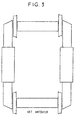
- la figure 3 représente schématiquement un bogie motorisé de l'art antérieur de type mixte à un essieu moteur et un essieu porteur, dont l'essieu moteur est entraíné par un seul moteur placé à l'extérieur du bogie.
- la figure 4 est une vue schématique du bogie motorisé de type bimoteur, muni de deux essieux conformément à l'invention dans une configuration à un moteur par essieu,
- les figures 5 à 8 représentent un essieu conforme à l'invention dans une configuration à un moteur par essieu.
- FIG. 1 is a schematic view of a motorized bogie of the prior art of the four-engine type,
- FIG. 2 is a schematic view of a motorized bogie of the prior art of the twin-engine type by rail file,
- Figure 3 schematically shows a motorized bogie of the prior art of the mixed type with a driving axle and a carrying axle, the driving axle of which is driven by a single motor placed outside the bogie.
- FIG. 4 is a schematic view of the motorized bogie of twin-engine type, provided with two axles in accordance with the invention in a configuration with one motor per axle,
- Figures 5 to 8 show an axle according to the invention in a configuration with one motor per axle.
Dans le bogie motorisé de type quadrimoteur de l'art antérieur représenté à la figure 1, chaque roue est entraínée par un ensemble moto-réducteur accolé à la roue. Les quatre roues sont alors indépendantes en rotation.In the four-engine motorized bogie of art shown in Figure 1, each wheel is driven by a motor-reduction unit attached to the wheel. The four wheels are then independent in rotation.
Dans le bogie motorisé de type bimoteur par file de rail de l'art antérieur représenté à la figure 2, chaque moteur entraíne par l'intermédiaire de deux réducteurs les deux roues situées du même coté du bogie.In the twin-engine motorized bogie per line of prior art rail shown in Figure 2, each motor drives through two reducers two wheels located on the same side of the bogie.
Les deux roues situées du même côté sont donc liées en rotation mais il y a indépendance en rotation des roues de la file droite du bogie avec les roues de la filé gauche.The two wheels on the same side are therefore linked in rotation but there is independence in rotation of the wheels of the right line of the bogie with the wheels of the left yarn.
Dans le bogie motorisé de type mixte de l'art antérieur à un essieu moteur et un essieu porteur, représenté à la figure 3, le moteur de l'essieu motorisé est placé hors du bogie, longitudinalement sous la caisse.In the motorized bogie of mixed type of art prior to a driving axle and a carrying axle, shown in Figure 3, the motor of the powered axle is placed outside the bogie, longitudinally under the body.
Le moteur entraíne par l'intermédiaire d'un arbre de type à cardans un couple conique logé dans un réducteur placé à proximité de l'une des deux roues. Du couple conique le mouvement est envoyé sur l'une des roues directement par un train d'engrenages plan et sur la deuxième roue par un deuxième train d'engrenages plan identique au précédent mais par l'intermédiaire d'un arbre de liaison situé suffisamment bas pour permettre un plancher du véhicule, par exemple à 350 mm au dessus du niveau du rail.The motor drives via a shaft of cardan type a bevel gear pair housed in a reduction gear placed near one of the two wheels. Conical couple the movement is sent to one of the wheels directly by a flat gear train and on the second wheel by a second plane gear train identical to the previous one but via a connecting shaft located sufficiently low to allow a vehicle floor, for example at 350 mm above the level of the rail.
Dans le bogie motorisé de type bimoteur, muni de deux essieux selon l'invention dans une configuration à un moteur par essieu (figure 4), le moteur de l'essieu entraíne un double train d'engrenages.In the twin-engine motorized bogie, equipped with two axles according to the invention in a single engine configuration per axle (Figure 4), the axle motor drives a double gear train.
Le moteur entraíne un premier étage à partir duquel le mouvement est distribué, par l'intermédiaire d'un deuxième étage, directement sur la roue côté moteur et via un arbre de transmission (passant sous la partie basse du plancher de caisse, par exemple à 350mm) sur la roue côté opposé au moteur.The engine drives a first stage from which the movement is distributed, via a second stage, directly on the wheel on the motor side and via a shaft transmission (passing under the lower part of the floor of body, for example 350mm) on the wheel opposite the engine.
Les deux essieux sont reliés l'un à l'autre par deux longerons dont l'une des extrémités de chacun d'entre eux est fixée rigidement à l'un des essieux et l'autre extrémité est fixée à l'autre essieu par l'intermédiaire d'une articulation élastique dont le rôle est de permettre au bogie d'absorber les gauches de voie.The two axles are connected to each other by two spars, one of the ends of each of which is rigidly attached to one of the axles and the other end is attached to the other axle via a elastic joint whose role is to allow the bogie to absorb the track lefts.
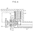
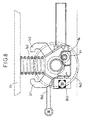
Les figures 5 à 8 représentent un essieu conforme à l'invention dans une configuration à un moteur par essieu.Figures 5 to 8 show an axle conforming to the invention in a configuration with one axle motor.
Le tableau 1 montre les différentes configurations possibles procurées par l'essieu conforme à l'invention.Table 1 shows the different configurations possible provided by the axle according to the invention.
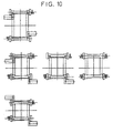
Le tableau 2 montre les différentes configurations possibles de bogies créées à partir de deux essieux selon l'invention.Table 2 shows the different configurations possible bogies created from two axles according to the invention.
Dans l'essieu selon l'invention, la caisse Cv du véhicule repose sur la poutre du pont en forme de portique Pr, par l'intermédiaire des suspensions secondaires Sp1 et Sp2 placées entre les roues à la verticale de l'essieu.In the axle according to the invention, the vehicle body Cv rests on the gantry-shaped bridge beam Pr, by means of the secondary suspensions Sp 1 and Sp 2 placed between the wheels vertically above the axle.
La poutre du pont Pr reçoit des roulements autour desquels tournent les deux moyeux de roues Mo1 et Mo2 qui portent les roues Ro1 et Ro2 , ainsi que les disques de frein. The beam of the bridge Pr receives bearings around which rotate the two wheel hubs Mo 1 and Mo 2 which carry the wheels Ro 1 and Ro 2 , as well as the brake discs.
Une première modularité de l'essieu selon l'invention réside alors en ce qu'il peut recevoir un à deux disques de frein Di1 et Di2 suivant les configurations et les besoins:
- essieu à roues liées en rotation, un ou deux disques de frein par essieu suivant l'énergie à dissiper,
- essieu à roues indépendantes en rotation, un disque de frein par roue.
- axle with wheels linked in rotation, one or two brake discs per axle depending on the energy to be dissipated,
- axle with independent rotating wheels, one brake disc per wheel.
Un étrier de freinage Et, accroché à la poutre du pont par les cornes Cr1 et Cr2, coiffe le disque Di1.A brake caliper And, hung on the bridge beam by the horns Cr1 and Cr2, covers the disc Di1.
Les roues Ro1 et Ro2 ne sont pas calées mais boulonnées aux moyeux de roues. Les roues sont donc de ce fait facilement déposables pour être reprofilées sans qu'il y ait besoin de tour en fosse.The wheels Ro 1 and Ro 2 are not locked but bolted to the wheel hubs. The wheels are therefore easily removable to be reprofiled without the need for a pit turn.
La poutre du pont est munie de part et d'autre de chaque appui de suspension secondaire de quatre plages de fixation qui peuvent recevoir, par pont:
- quatre butées transversales si l'essieu selon l'invention est utilisé en essieu seul,
- deux butées transversales Bt1 et Bt2 , un longeron de châssis Lc et une articulation de châssis Ac si l'essieu selon l'invention est utilisé par paire pour former un bogie articulé.
- four transverse stops if the axle according to the invention is used as an axle alone,
- two transverse stops Bt 1 and Bt 2 , a chassis beam Lc and a chassis joint Ac if the axle according to the invention is used in pairs to form an articulated bogie.
Une deuxième modularité de l'essieu selon l'invention réside alors en ce que les interfaces de fixation des butées transversales, longeron de châssis et articulation de châssis sur la poutre du pont sont identiques de façon à pouvoir placer ces organes indifféremment suivant la configuration souhaitée: ceci permet en particulier en modifiant la longueur des longerons de châssis qui relient les deux essieux de procurer un bogie à empattement court, moyen ou long.A second modularity of the axle according to the invention then resides in that the interfaces for fixing the stops transverse, chassis beam and articulation of chassis on the bridge beam are identical so be able to place these organs indifferently according to the desired configuration: this allows in particular changing the length of the chassis beams that connect both axles to provide a short wheelbase bogie, medium or long.
La poutre du pont est munie d'une plage de fixation de bielle d'entraínement basse Bb et deux plages de fixation de bielles d'entraínement hautes Bh1 et Bh2, ces deux bielles d'entraínement hautes étant montées par exemple si l'essieu selon l'invention est utilisé en essieu seul. The bridge beam is provided with a fixing range of low drive rod Bb and two fixing ranges of high drive rods Bh1 and Bh2, these two rods high drive being mounted for example if the axle according to the invention is used as an axle alone.
Sur les moyeux de roue Mo1 et Mo2 sont calées les couronnes dentées Co1 et Co2 qui, associées aux pignons Pi1 et Pi2 forment le deuxième étage de réduction de la chaíne cinématique. Un arbre de liaison Ar peut être monté sur le même axe de rotation que celui des pignons Pi1 et Pi2 de façon à lier en rotation les deux roues de l'essieu.On the wheel hubs Mo 1 and Mo 2 are fixed the gear rings Co 1 and Co 2 which, associated with the pinions Pi 1 and Pi 2 form the second reduction stage of the kinematic chain. A connecting shaft Ar can be mounted on the same axis of rotation as that of the pinions Pi 1 and Pi 2 so as to link the two wheels of the axle in rotation.
Une troisième modularité de l'essieu selon l'invention réside alors en ce que les deux roues de l'essieu peuvent être indépendantes ou liées en rotation suivant l'absence ou la présence de l'arbre de liaison.A third modularity of the axle according to the invention then lies in that the two wheels of the axle can be independent or linked in rotation according to the absence or the presence of the connecting shaft.
Le premier étage de réduction de la chaíne cinématique est constitué d'un pignon Pj, calé sur l'arbre du moteur, des roues intermédiaires dentées Ri et Rj, et de la roue dentée Rk montée sur le même arbre que les pignons Pi. L'ensemble que constitue le premier étage de réduction est monté dans un carter de mécanique indépendant Ca boulonné à la poutre du pont Pr. Le moteur de traction Mt est flasqué sur ce carter Ca.The first reduction stage of the kinematic chain consists of a pinion Pj, wedged on the motor shaft, intermediate toothed wheels Ri and Rj, and the wheel toothed Rk mounted on the same shaft as the pinions Pi. The assembly which constitutes the first reduction stage is mounted in an independent mechanical housing Ca bolted to the beam of the Pr bridge. The traction motor Mt is flanged on this Ca housing.
Une quatrième modularité de l'essieu selon l'invention réside alors en ce que le carter de mécanique Ca et le moteur Mt peuvent être placés indifféremment de l'un ou l'autre des côtés de l'essieu, ou simultanément des deux côtés permettant ainsi les trois configurations de motorisation suivante:
- un ensemble carter de mécanique Ca et moteur Mt par essieu associé avec un arbre de transmission Ar liant ainsi les deux roues en rotation,
- un ensemble carter de mécanique Ca et moteur Mt par côté sans arbre de transmission Ar rendant ainsi les deux roues indépendantes en rotation,
- un ensemble carter de mécanique Ca et moteur Mt par côté associé avec un arbre de transmission Ar liant les deux roues en rotation (solution où le moteur est physiquement réparti).
- an assembly of mechanical housing Ca and motor Mt per axle associated with a drive shaft Ar thus connecting the two wheels in rotation,
- a mechanical housing Ca and motor Mt assembly on each side without Ar drive shaft thus making the two independent wheels in rotation,
- a mechanical housing assembly Ca and motor Mt per side associated with a transmission shaft Ar connecting the two rotating wheels (solution where the motor is physically distributed).
La non installation dans l'essieu du moteur Mt, de l'ensemble des engrenages implanté dans le carter de mécanique Ca et la poutre du pont Pr, permet de décliner le bogie moteur en un bogie porteur ce avec une très forte synergie.The non-installation in the axle of the Mt motor, of the set of gears installed in the housing mechanical Ca and the beam of the Pr bridge, allows to decline the motor bogie in a carrying bogie with very strong synergy.
Une cinquième modularité de l'essieu selon l'invention réside alors en ce que l'essieu porteur est transformable en essieu moteur par ajout d'organes, et l'essieu moteur transformable en essieu porteur, par suppression d'organes.A fifth modularity of the axle according to the invention then resides in that the carrying axle is convertible into drive axle by adding components, and the drive axle convertible into a carrying axle by removing organs.
Claims (11)
- A bogie comprising one or more axles and adapted to be fitted to an integral low-floor vehicle, said axle or at least one of said axles comprising a support beam (Pr) for supporting a load and receiving hubs (Mo1, Mo2) carrying wheels (Rol, Ro2), which bogie is characterized in that said support beam (Pr) contains at least some of the units for transmitting motion between at least one motor (Mt) disposed parallel to said axle and said wheels (Rol, Ro2) on said axle.
- A bogie according to claim 1, wherein said axle motor(s) (Mt) drive a double gear train.
- A bogie according to either claim 1 or claim 2, wherein said motor(s) drive(s) a first stage from which motion is transmitted via a second stage to the motor side wheel directly and to the wheel on the side opposite the motor via a transmission shaft (Ar).
- A bogie according to any of claims 1 to 3, wherein said axles are interconnected by two longitudinal members, one end of each of which is fixed rigidly to one of the axles and the other end of each of which is fixed to the other axle via an elastic articulation.
- A bogie according to any of claims 1 to 4, wherein at least one of said wheels (Ro1, Ro2) is fitted with a brake disc and caliper assembly.
- A bogie according to any of claims 1 to 5, wherein at least one of said axles is a motor axle.
- A bogie according to any of claims 1 to 5, wherein at least one of said axles is a support axle.
- A bogie according to any of claims 1 to 5, wherein one of said axles is a motor axle and the [sic] other axle is a support axle.
- A bogie according to any of claims 1 to 8 having a short, medium or long wheelbase.
- An integral low-floor vehicle including a bogie according to any of claims 1 to 9 and equipped with 16 seats positioned in the body in line with the bogie.
- An integral low-floor vehicle including a bogie according to any of claims 1 to 9 and wherein the body is provided with an access door at each corner of the bogie.
Applications Claiming Priority (2)
| Application Number | Priority Date | Filing Date | Title |
|---|---|---|---|
| FR9713290 | 1997-10-23 | ||
| FR9713290A FR2770190B1 (en) | 1997-10-23 | 1997-10-23 | BOGIE-FORMING AXLE OR TORQUE FOR RAILWAY VEHICLE WITH INTEGRAL LOW FLOOR |
Publications (2)
| Publication Number | Publication Date |
|---|---|
| EP0911239A1 EP0911239A1 (en) | 1999-04-28 |
| EP0911239B1 true EP0911239B1 (en) | 2003-08-27 |
Family
ID=9512556
Family Applications (1)
| Application Number | Title | Priority Date | Filing Date |
|---|---|---|---|
| EP19980402637 Expired - Lifetime EP0911239B1 (en) | 1997-10-23 | 1998-10-23 | Bogie with one or more axles for a low-floor vehicle |
Country Status (6)
| Country | Link |
|---|---|
| EP (1) | EP0911239B1 (en) |
| DE (1) | DE69817494T2 (en) |
| DK (1) | DK0911239T3 (en) |
| ES (1) | ES2206871T3 (en) |
| FR (1) | FR2770190B1 (en) |
| PT (1) | PT911239E (en) |
Families Citing this family (8)
| Publication number | Priority date | Publication date | Assignee | Title |
|---|---|---|---|---|
| DE19956976C2 (en) | 1999-11-26 | 2001-09-06 | Gutehoffnungshuette Radsatz | Idler wheel axle for rail vehicles |
| FR2914609B1 (en) | 2007-04-05 | 2009-07-10 | Alstom Transport Sa | BOGIE FOR RAILWAY VEHICLE |
| DE202008007471U1 (en) | 2008-05-30 | 2008-12-11 | Vecon Trading & Engineering | Bogie with engine-gearbox-clutch unit |
| KR101155337B1 (en) * | 2010-09-10 | 2012-06-19 | 한국철도기술연구원 | wheel clutch for a low floor railway vehicle |
| DE102012002716B3 (en) * | 2012-02-14 | 2013-05-29 | Voith Patent Gmbh | A rail |
| RU2566594C2 (en) * | 2014-03-12 | 2015-10-27 | Акционерное общество "Уральский завод транспортного машиностроения" (АО "Уралтрансмаш") | Railway vehicle drive bogie, mainly, of low-floor tram |
| FR3056180B1 (en) * | 2016-09-20 | 2019-06-28 | Alstom Transport Technologies | OPTIMIZED BOGIE FOR A RAILWAY VEHICLE, IN PARTICULAR FOR TRAMWAY |
| DE102017102138A1 (en) | 2017-02-03 | 2018-08-09 | Andreas Fiedler | System for connecting a gearbox with a wheel set shaft and arrangement for a bogie for rail vehicles |
Family Cites Families (3)
| Publication number | Priority date | Publication date | Assignee | Title |
|---|---|---|---|---|
| FR2624079B1 (en) * | 1987-12-03 | 1992-04-30 | Alsthom | BOGIE FOR RAIL VEHICLE WITH MECHANICAL DIFFERENTIAL TRANSMISSION |
| FR2654402B1 (en) * | 1989-11-14 | 1992-01-10 | Alsthom Gec | DEVICE FOR DRIVING INDEPENDENT WHEELS IN ROTATION OF A RAILWAY VEHICLE WITH A MOTOR AXLE. |
| DE4419362A1 (en) * | 1994-06-03 | 1995-12-07 | Bergische Stahlindustrie | Articulated carriage with low corridor, for inner city rail networks |
-
1997
- 1997-10-23 FR FR9713290A patent/FR2770190B1/en not_active Expired - Lifetime
-
1998
- 1998-10-23 DE DE69817494T patent/DE69817494T2/en not_active Expired - Lifetime
- 1998-10-23 EP EP19980402637 patent/EP0911239B1/en not_active Expired - Lifetime
- 1998-10-23 PT PT98402637T patent/PT911239E/en unknown
- 1998-10-23 ES ES98402637T patent/ES2206871T3/en not_active Expired - Lifetime
- 1998-10-23 DK DK98402637T patent/DK0911239T3/en active
Also Published As
| Publication number | Publication date |
|---|---|
| PT911239E (en) | 2004-01-30 |
| ES2206871T3 (en) | 2004-05-16 |
| DE69817494T2 (en) | 2004-06-24 |
| FR2770190A1 (en) | 1999-04-30 |
| FR2770190B1 (en) | 1999-12-31 |
| DK0911239T3 (en) | 2003-12-22 |
| DE69817494D1 (en) | 2003-10-02 |
| EP0911239A1 (en) | 1999-04-28 |
Similar Documents
| Publication | Publication Date | Title |
|---|---|---|
| EP1270359B1 (en) | Motorized bogie for a low-floor railway vehicle | |
| EP2132080B1 (en) | Railway vehicle comprising pivoting end bogies | |
| EP3159237B1 (en) | Railway vehicle having at least a lowered bogie | |
| EP3159236B2 (en) | Railway vehicle having a lowered bogie | |
| EP0911239B1 (en) | Bogie with one or more axles for a low-floor vehicle | |
| KR101527447B1 (en) | Concrete rail grinding apparatus of an light electric railway | |
| FR2720361A1 (en) | Bogie for a railway vehicle. | |
| EP1977949A1 (en) | Bogie for rail vehicle | |
| CA2216005C (en) | Articulated rail truck frame and truck including such a frame | |
| EP0364847B1 (en) | Motor bogie for a railway vehicle with a low floor over its whole length | |
| JP2004276730A (en) | Truck for railway vehicle and low-floor vehicle using it | |
| EP0630799B1 (en) | Running gear for a vehicle travelling along guided tracks | |
| EP3521125A1 (en) | Bogie for rail vehicle | |
| EP0136219A1 (en) | Road-rail vehicle | |
| EP1958845B1 (en) | Railway carriage for passengers, and corresponding passenger transport train | |
| EP0861350A1 (en) | Mobile maintenance and repair apparatus for railway lines | |
| FR2782678A1 (en) | Axle for vehicle with lowered floor e.g. public transport vehicles, has drive transmission units located below floor, with crown wheel gear to transmit drive through to horizontal shafts driving through gears to wheels | |
| FR2465029A1 (en) | BOURREUSE OF RAILWAYS | |
| EP4074572A1 (en) | Rail vehicle motor bogie |
Legal Events
| Date | Code | Title | Description |
|---|---|---|---|
| PUAI | Public reference made under article 153(3) epc to a published international application that has entered the european phase |
Free format text: ORIGINAL CODE: 0009012 |
|
| AK | Designated contracting states |
Kind code of ref document: A1 Designated state(s): BE DE DK ES GB IT NL PT SE |
|
| AX | Request for extension of the european patent |
Free format text: AL;LT;LV;MK;RO;SI |
|
| 17P | Request for examination filed |
Effective date: 19991028 |
|
| AKX | Designation fees paid |
Free format text: BE DE DK ES GB IT NL PT SE |
|
| 17Q | First examination report despatched |
Effective date: 20020531 |
|
| GRAH | Despatch of communication of intention to grant a patent |
Free format text: ORIGINAL CODE: EPIDOS IGRA |
|
| RTI1 | Title (correction) |
Free format text: BOGIE WITH ONE OR MORE AXLES FOR A LOW-FLOOR VEHICLE |
|
| GRAS | Grant fee paid |
Free format text: ORIGINAL CODE: EPIDOSNIGR3 |
|
| GRAA | (expected) grant |
Free format text: ORIGINAL CODE: 0009210 |
|
| AK | Designated contracting states |
Designated state(s): BE DE DK ES GB IT NL PT SE |
|
| REG | Reference to a national code |
Ref country code: GB Ref legal event code: FG4D Free format text: NOT ENGLISH |
|
| REF | Corresponds to: |
Ref document number: 69817494 Country of ref document: DE Date of ref document: 20031002 Kind code of ref document: P |
|
| RAP2 | Party data changed (patent owner data changed or rights of a patent transferred) |
Owner name: ALSTOM TRANSPORT S.A. |
|
| REG | Reference to a national code |
Ref country code: DK Ref legal event code: T3 |
|
| REG | Reference to a national code |
Ref country code: SE Ref legal event code: TRGR |
|
| GBT | Gb: translation of ep patent filed (gb section 77(6)(a)/1977) |
Effective date: 20031220 |
|
| NLT2 | Nl: modifications (of names), taken from the european patent patent bulletin |
Owner name: ALSTOM TRANSPORT S.A. |
|
| REG | Reference to a national code |
Ref country code: PT Ref legal event code: PD4A Free format text: ALSTOM TRANSPORT SA FR Effective date: 20031127 |
|
| REG | Reference to a national code |
Ref country code: ES Ref legal event code: FG2A Ref document number: 2206871 Country of ref document: ES Kind code of ref document: T3 |
|
| PLBE | No opposition filed within time limit |
Free format text: ORIGINAL CODE: 0009261 |
|
| STAA | Information on the status of an ep patent application or granted ep patent |
Free format text: STATUS: NO OPPOSITION FILED WITHIN TIME LIMIT |
|
| 26N | No opposition filed |
Effective date: 20040528 |
|
| PGFP | Annual fee paid to national office [announced via postgrant information from national office to epo] |
Ref country code: SE Payment date: 20091014 Year of fee payment: 12 Ref country code: DK Payment date: 20091014 Year of fee payment: 12 |
|
| PGFP | Annual fee paid to national office [announced via postgrant information from national office to epo] |
Ref country code: NL Payment date: 20091016 Year of fee payment: 12 |
|
| PGFP | Annual fee paid to national office [announced via postgrant information from national office to epo] |
Ref country code: PT Payment date: 20091013 Year of fee payment: 12 |
|
| PGFP | Annual fee paid to national office [announced via postgrant information from national office to epo] |
Ref country code: BE Payment date: 20091130 Year of fee payment: 12 |
|
| BERE | Be: lapsed |
Owner name: S.A. *ALSTHOM TRANSPORT Effective date: 20101031 |
|
| REG | Reference to a national code |
Ref country code: PT Ref legal event code: MM4A Free format text: LAPSE DUE TO NON-PAYMENT OF FEES Effective date: 20110426 |
|
| REG | Reference to a national code |
Ref country code: NL Ref legal event code: V1 Effective date: 20110501 |
|
| REG | Reference to a national code |
Ref country code: DK Ref legal event code: EBP |
|
| PG25 | Lapsed in a contracting state [announced via postgrant information from national office to epo] |
Ref country code: PT Free format text: LAPSE BECAUSE OF NON-PAYMENT OF DUE FEES Effective date: 20110426 |
|
| PG25 | Lapsed in a contracting state [announced via postgrant information from national office to epo] |
Ref country code: BE Free format text: LAPSE BECAUSE OF NON-PAYMENT OF DUE FEES Effective date: 20101031 Ref country code: NL Free format text: LAPSE BECAUSE OF NON-PAYMENT OF DUE FEES Effective date: 20110501 |
|
| PG25 | Lapsed in a contracting state [announced via postgrant information from national office to epo] |
Ref country code: SE Free format text: LAPSE BECAUSE OF NON-PAYMENT OF DUE FEES Effective date: 20101024 |
|
| PG25 | Lapsed in a contracting state [announced via postgrant information from national office to epo] |
Ref country code: DK Free format text: LAPSE BECAUSE OF NON-PAYMENT OF DUE FEES Effective date: 20101031 |
|
| REG | Reference to a national code |
Ref country code: DE Ref legal event code: R082 Ref document number: 69817494 Country of ref document: DE Representative=s name: DREISS PATENTANWAELTE PARTG MBB, DE Ref country code: DE Ref legal event code: R081 Ref document number: 69817494 Country of ref document: DE Owner name: ALSTOM TRANSPORT TECHNOLOGIES, FR Free format text: FORMER OWNER: GEC ALSTHOM TRANSPORT S.A., PARIS, FR |
|
| REG | Reference to a national code |
Ref country code: GB Ref legal event code: 732E Free format text: REGISTERED BETWEEN 20151119 AND 20151125 |
|
| REG | Reference to a national code |
Ref country code: DE Ref legal event code: R082 Ref document number: 69817494 Country of ref document: DE Representative=s name: DREISS PATENTANWAELTE PARTG MBB, DE Ref country code: DE Ref legal event code: R081 Ref document number: 69817494 Country of ref document: DE Owner name: ALSTOM TRANSPORT TECHNOLOGIES, FR Free format text: FORMER OWNER: ALSTOM TRANSPORT TECHNOLOGIES, LEVALLOIS-PERRET, FR |
|
| PGFP | Annual fee paid to national office [announced via postgrant information from national office to epo] |
Ref country code: DE Payment date: 20171019 Year of fee payment: 20 |
|
| PGFP | Annual fee paid to national office [announced via postgrant information from national office to epo] |
Ref country code: IT Payment date: 20171023 Year of fee payment: 20 Ref country code: GB Payment date: 20171019 Year of fee payment: 20 Ref country code: ES Payment date: 20171121 Year of fee payment: 20 |
|
| REG | Reference to a national code |
Ref country code: DE Ref legal event code: R071 Ref document number: 69817494 Country of ref document: DE |
|
| REG | Reference to a national code |
Ref country code: GB Ref legal event code: PE20 Expiry date: 20181022 |
|
| PG25 | Lapsed in a contracting state [announced via postgrant information from national office to epo] |
Ref country code: GB Free format text: LAPSE BECAUSE OF EXPIRATION OF PROTECTION Effective date: 20181022 |
|
| REG | Reference to a national code |
Ref country code: ES Ref legal event code: FD2A Effective date: 20200806 |
|
| PG25 | Lapsed in a contracting state [announced via postgrant information from national office to epo] |
Ref country code: ES Free format text: LAPSE BECAUSE OF EXPIRATION OF PROTECTION Effective date: 20181024 |
|
| REG | Reference to a national code |
Ref country code: ES Ref legal event code: PC2A Owner name: ALSTOM TRANSPORT TECHNOLOGIES Effective date: 20210601 |