EP0911233A1 - Device for washing and polishing vehicles - Google Patents
Device for washing and polishing vehicles Download PDFInfo
- Publication number
- EP0911233A1 EP0911233A1 EP98117222A EP98117222A EP0911233A1 EP 0911233 A1 EP0911233 A1 EP 0911233A1 EP 98117222 A EP98117222 A EP 98117222A EP 98117222 A EP98117222 A EP 98117222A EP 0911233 A1 EP0911233 A1 EP 0911233A1
- Authority
- EP
- European Patent Office
- Prior art keywords
- drive shaft
- bearing housing
- axis
- rotation
- support ring
- Prior art date
- Legal status (The legal status is an assumption and is not a legal conclusion. Google has not performed a legal analysis and makes no representation as to the accuracy of the status listed.)
- Granted
Links
Images


Classifications
-
- B—PERFORMING OPERATIONS; TRANSPORTING
- B60—VEHICLES IN GENERAL
- B60S—SERVICING, CLEANING, REPAIRING, SUPPORTING, LIFTING, OR MANOEUVRING OF VEHICLES, NOT OTHERWISE PROVIDED FOR
- B60S3/00—Vehicle cleaning apparatus not integral with vehicles
- B60S3/04—Vehicle cleaning apparatus not integral with vehicles for exteriors of land vehicles
- B60S3/06—Vehicle cleaning apparatus not integral with vehicles for exteriors of land vehicles with rotary bodies contacting the vehicle
- B60S3/063—Vehicle cleaning apparatus not integral with vehicles for exteriors of land vehicles with rotary bodies contacting the vehicle the axis of rotation being approximately vertical
Definitions
- the invention relates to a device for washing or Polishing vehicles with at least one to their vertical axis (axis of rotation) rotatably mounted Work roll, which a multitude of individual work elements, such as bristles, rags, strips or the like. and which are rotatable in a rack and in the direction its axis of rotation is arranged displaceably, wherein Work roll and vehicle essentially vertical are movable relative to each other relative to the axis of rotation.
- axis axis of rotation
- DE-OS 16 30 469 discloses a device for Washing vehicles with a total of three washing rollers, two of which have essentially vertical axes of rotation and a drivable around a horizontal axis of rotation are stored in a rack. In addition, the Wash rollers at the same time a back and forth Carry out movement in the direction of their axes of rotation. In DE-OS 16 30 469, however, is no further information about what special means the back and forth movement is effected.
- washing roller for driving and storing a washing roller with in essentially vertical axis of rotation a vertical drive shaft to be provided in a bearing housing is rotatably mounted.
- the work roll is with the lower end of this drive shaft connectable while at the upper end of the drive shaft from engine and Gearbox attacks existing drive unit.
- the Drive unit is fixed to the upper end of the Bearing housing connected.
- the bearing housing itself is over a horizontal pivot axis that is transverse to the relative direction of movement runs from vehicle and frame, swiveling stored in a carriage.
- the washing roller carries no additional Movement in the direction of its axis of rotation.
- the invention has for its object a device for washing or polishing vehicles at the beginning the kind mentioned to show a simple Has structure, is inexpensive to manufacture and ensures a good washing or polishing result.
- Planetary gear By concentrically surrounding the drive shaft Planetary gear is a simple structure and also achieved a very compact design.
- the planetary gear sets the support ring opposite the drive shaft in rotation and by means of the oblique Support surface and the drive roller one in the direction the axis of rotation reciprocating movement of the drive shaft and with it the one connected with it Work roll. As a result, it is not a separate drive motor with gear to generate the opening and Movement of the drive shaft or the work roll required.
- the reduction ratio can by appropriate interpretation of the planetary gear can be chosen so that a optimal washing or polishing effect is achieved.
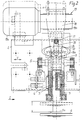
- a device for washing or polishing vehicles.
- a frame 1 e.g. a portal
- a carriage 2 horizontally and transversely to the relative movement direction B of Vehicle and work roll slidably mounted.
- a bearing housing 3 around a horizontal Swivel axis S pivoted.
- the pivot axis S also runs transversely to the relative direction of movement B, i.e. in the direction of displacement V of the carriage 2.
- An intermediate bush 4 can be rotated in the bearing housing 3 stored.
- this intermediate sleeve 4 there is essentially one vertical drive shaft 5 in the direction of its axis of rotation A arranged axially displaceable.
- the drive shaft 5 is fixed to a flange 6 with which a work roll is connectable.
- the top of this Work roll 7 is only shown in broken lines in FIG.
- the work roll itself points in a known manner a multitude of individual working elements, such as bristles, Rags, strips or the like., With the working elements the respective application of the work roll 7 as a washing roll or polishing roller are adapted.
- the drive shaft 5 is above the bearing housing 3 surrounded by a support ring 8 concentrically.
- This Support ring 8 is opposite by means of the support pot 9 the drive shaft 5 rotatable, but axially immovable stored.
- the support ring 8 has at its lower End a support surface inclined to the axis of rotation A. 8a, which is supported on a support roller 10.
- the support surface 8a is opposite to the axis of rotation A so inclined that the desired axial stroke H the drive shaft 5 or the work roll connected to it 7 results.
- a stroke H of about 60 mm has proven to be proven particularly suitable.
- the support roller 10 is on a support arm 11 mounted, which in turn with the Bearing housing 3 is connected.
- a planet carrier 15 is on the drive shaft rotatably mounted and carries one with the Sun gear 13 and the ring gear 14 meshing planet gear 16.
- a connecting tab 17 grips him with one described in more detail below Holding arm 18 is connected.
- Support ring 8 and planetary gear 12 above the Bearing housing 3 is particularly advantageous if one the other components and assemblies of the washing or would like to keep the polishing system largely unchanged. If necessary, however, the support ring 8 and that Planetary gear 12 also below the bearing housing 3 be arranged.
- a drive unit 19 consisting of motor 19a and gear 19b, arranged.
- This drive unit 19 is from the Drive shaft 5 worn.
- a support arm 18 is connected to a vertical Has longitudinal slot 20.
- this longitudinal slot 20th engages a roller 21 which is mounted on the support arm 11 is.
- the holding arm 18 is opposite the bearing housing 3 fixed non-rotatably, however axially displaceable in the direction of the axis of rotation A.
- the Holding arm 18 is used to transmit the reaction force of the drive unit 19 onto the bearing housing 3.
- the drive shaft 5 is driven by the drive unit 19 at the desired speed of 120 rpm, for example driven.
- the sun gear 13 connected to it drives over the planet gear 16 to the ring gear.
- This will the carrying pot 9 and the support ring 8 connected to it with reduced speed according to the selected one Reduction ratio of the planetary gear 12 from for example 2: 1 driven.
- the Support ring 8 runs on its inclined support surface 8a the support roller 10, whereby the drive shaft 5 in a vertical up and down movement is offset.
- a drive shaft speed of 120 rpm and a reduction ratio of 2: 1 is the Stroke frequency 60 strokes per minute.
- Drive unit 19 moves up and down. If the washing roller 7 by the vehicle in the relative direction of movement B is swung out, then drive shaft 5, the bearing housing 3, the support ring 8 and the drive unit 19 a corresponding pivoting movement, as shown in Figure 1 with dash-dotted lines is.
Abstract
Description
Die Erfindung betrifft eine Vorrichtung zum Waschen oder Polieren von Fahrzeugen mit mindestens einer, um ihre vertikale Achse (Drehachse) drehantreibbar gelagerten Arbeitswalze, welche eine Vielzahl einzelner Arbeitselemente, wie Borsten, Lappen, Streifen oder dgl. aufweist, und welche in einem Gestell drehbar und in Richtung ihrer Drehachse verschiebbar angeordnet ist, wobei Arbeitswalze und Fahrzeug im wesentlichen senkrecht zur Drehachse relativ zueinander bewegbar sind.The invention relates to a device for washing or Polishing vehicles with at least one to their vertical axis (axis of rotation) rotatably mounted Work roll, which a multitude of individual work elements, such as bristles, rags, strips or the like. and which are rotatable in a rack and in the direction its axis of rotation is arranged displaceably, wherein Work roll and vehicle essentially vertical are movable relative to each other relative to the axis of rotation.
Die DE-OS 16 30 469 offenbart eine Vorrichtung zum Waschen von Fahrzeugen mit insgesamt drei Waschwalzen, von denen zwei um im wesentlichen vertikale Drehachsen und eine um eine horizontale Drehachse drehantreibbar in einem Gestell gelagert sind. Außerdem sollen die Waschwalzen gleichzeitig eine hin- und hergehende Bewegung in Richtung ihrer Drehachsen ausführen. In der DE-OS 16 30 469 sind jedoch keine weiteren Angaben darüber enthalten, durch welche speziellen Mittel die hin- und hergehende Bewegung bewirkt wird.DE-OS 16 30 469 discloses a device for Washing vehicles with a total of three washing rollers, two of which have essentially vertical axes of rotation and a drivable around a horizontal axis of rotation are stored in a rack. In addition, the Wash rollers at the same time a back and forth Carry out movement in the direction of their axes of rotation. In DE-OS 16 30 469, however, is no further information about what special means the back and forth movement is effected.
Weiterhin ist es bei Vorrichtungen zum Waschen oder Polieren von Fahrzeugen bekannt (vgl. DE 195 24 748 A1), zum Antrieb und zur Lagerung einer Waschwalze mit im wesentlichen vertikaler Drehachse eine vertikale Antriebswelle vorzusehen, die in einem Lagergehäuse drehbar gelagert ist. Die Arbeitswalze ist mit dem unteren Ende dieser Antriebswelle verbindbar, während am oberen Ende der Antriebswelle ein aus Motor und Getriebe bestehendes Antriebsaggregat angreift. Das Antriebsaggregat ist hierbei fest mit dem oberen Ende des Lagergehäuses verbunden. Das Lagergehäuse selbst ist um eine horizontale Schwenkachse, die quer zur Relativbewegungsrichtung von Fahrzeug und Gestell verläuft, schwenkbar in einem Laufwagen gelagert. Bei dieser bekannten Waschvorrichtung führt Jedoch die Waschwalze keine zusätzliche Bewegung in Richtung ihrer Drehachse aus. Dies hat den Nachteil, daß in unmittelbarer Nähe von vorstehenden Teilen, wie Schrammleisten, Zierleisten, Rückspiegeln und dgl., sowie auch bei Vertiefungen z.B. im Fensterbereich, Zonen verbleiben, in denen der Schmutz überhaupt nicht oder nur ungenügend entfernt wird. Diese Zonen werden als "Waschschatten" bezeichnet und sind darauf zurückzuführen, daß die Waschelemente durch die vorstehenden Teile zur Seite gedrängt werden.Furthermore, it is in devices for washing or Polishing of vehicles is known (cf. DE 195 24 748 A1), for driving and storing a washing roller with in essentially vertical axis of rotation a vertical drive shaft to be provided in a bearing housing is rotatably mounted. The work roll is with the lower end of this drive shaft connectable while at the upper end of the drive shaft from engine and Gearbox attacks existing drive unit. The Drive unit is fixed to the upper end of the Bearing housing connected. The bearing housing itself is over a horizontal pivot axis that is transverse to the relative direction of movement runs from vehicle and frame, swiveling stored in a carriage. In this known Washing device However, the washing roller carries no additional Movement in the direction of its axis of rotation. This has the disadvantage that in the immediate vicinity of protruding parts, such as curb strips, decorative strips, Rear-view mirrors and the like, as well as recesses e.g. remain in the window area, zones in which the Dirt not removed at all or only insufficiently becomes. These zones are called "wash shadows" and are due to the fact that the washing elements be pushed aside by the above parts.
Der Erfindung liegt die Aufgabe zugrunde, eine Vorrichtung zum Waschen oder Polieren von Fahrzeugen der eingangs erwähnten Art aufzuzeigen, die einen einfachen Aufbau aufweist, kostengünstig herstellbar ist und ein gutes Wasch- bzw. Polierergebnis sicherstellt.The invention has for its object a device for washing or polishing vehicles at the beginning the kind mentioned to show a simple Has structure, is inexpensive to manufacture and ensures a good washing or polishing result.
Dies wird bei einer Vorrichtung zum Waschen oder Polieren der eingangs erwähnten Art nach der Erfindung dadurch erreicht, daß eine mit dem oberen Ende der Arbeitswalze verbindbare, im wesentlichen vertikale Antriebewelle in einer Zwischenbüchse axial verschiebbar ist, daß die Zwischenbüchse in einem sie umgebenden, gegenüber dem Gestell abgestützten Lagergehäuse drehbar gelagert ist und daß die Antriebswelle oberhalb oder unterhalb des Lagergehäuses von einem Stützring konzentrisch umgeben ist, der gegenüber der Antriebswelle drehbar, jedoch axial unverschiebbar ist und an seinem unteren Ende eine gegenüber der Drehachse geneigte Stützfläche aufweist, mit welcher er sich auf einer von dem Lagergehäuse getragenen Stützrolle abstützt, daß zwischen Antriebswelle und Stützring ein Planetengetriebe angeordnet ist, dessen Planetenradträger ortsfest angeordnet ist, dessen Sonnenrad mit der Antriebswelle und dessen Hohlrad mit dem Stützring verbunden ist, daß am oberen Ende der Antriebswelle ein von dieser getragenes, aus Motor und Getriebe bestehendes Antriebsaggregat angeordnet ist und daß mit diesem zur Übertragung der Reaktionskraft desselben auf das Lagergehäuse ein Haltearm verbunden ist, der gegenüber dem Lagergehäuse unverdrehbar festgelegt, jedoch axial in Richtung der Drehachse verschiebbar ist.This will be the case with a device for washing or polishing of the type mentioned above according to the invention accomplished that with the top of the work roll connectable, essentially vertical drive shaft is axially displaceable in an intermediate sleeve, that the intermediate sleeve in a surrounding, opposite the frame supported bearing housing rotatable is mounted and that the drive shaft above or concentrically below the bearing housing by a support ring is surrounded, opposite the drive shaft rotatable, but axially immovable and on his lower end an inclined to the axis of rotation Has support surface with which he is on a supported by the support roller carried by the bearing housing, that between the drive shaft and support ring a planetary gear is arranged, the planet carrier is stationary, the sun gear with the Drive shaft and its ring gear with the support ring is connected to that at the upper end of the drive shaft one carried by the engine and transmission existing drive unit is arranged and that with this to transfer the reaction force of the same a holding arm is connected to the bearing housing is the non-rotatable relative to the bearing housing fixed, but axially in the direction of the axis of rotation is movable.
Durch das die Antriebswelle konzentrisch umgebende Planetengetriebe wird ein einfacher Aufbau und auch eine sehr kompakte Bauweise erreicht. Das Planetengetriebe setzt den Stützring gegenüber der Antriebswelle in Drehung und bewirkt mittels der schrägen Stützfläche und der Antriebsrolle eine in Richtung der Drehachse hin- und hergehende Bewegung der Antriebswelle und damit auch der mit ihr verbundenen Arbeitswalze. Es ist infolgedessen kein eigener Antriebsmotor mit Getriebe zur Erzeugung der Auf- und Abbewegung der Antriebswelle bzw. der Arbeitswalze erforderlich. Durch das Planetengetriebe findet eine Untersetzung der Drehzahl der Antriebswelle statt, d.h. der Stützring dreht sich mit einer geringeren Geschwindigkeit als die Antriebswelle. Das Untersetzungsverhältnis kann durch entsprechende Auslegung des Planetengetriebes so gewählt werden, daß ein optimaler Wasch- bzw. Poliereffekt erreicht wird. So hat es sich gezeigt, daß ein Untersetzungsverhältnis von 2 : 1 besonders vorteilhaft ist. Wenn beispielsweise die Arbeitswalze mit einer Geschwindigkeit von 120 U/min angetrieben wird, dann führt die Arbeitswalze 60 Hübe pro Minute aus. Da die Hubfrequenz geringer ist als die Drehzahl, werden auch die durch die Auf- und Abbewegung der Arbeitswalze entstehenden Massenkräfte in Grenzen gehalten. Dank der kompakten Bauweise der erfindungsgemäßen Vorrichtung, kann diese in Portalwaschanlagen oder Waschstraßen herkömmlicher Bauweise eingesetzt werden. Es können daher die gleichen Baugruppen wie Portal (= Gestell), Laufwagen und dgl., wie sie für Waschwalzen, die keine Auf- und Abbewegung ausführen, verwendet werden, auch in Kombination mit der erfindungsgemäßen Vorrichtung eingesetzt werden. Auch dies ermöglicht eine kostengünstige Herstellung der gesamten Wasch- oder Polieranlage. Gegebenenfalls können sogar bestehende Wasch- oder Polieranlegen mit der erfindungsgemäßen Vorrichtung nachgerüstet werden, um bei den bestehenden Anlagen den Wasch- oder Poliereffekt zu verbessern.By concentrically surrounding the drive shaft Planetary gear is a simple structure and also achieved a very compact design. The planetary gear sets the support ring opposite the drive shaft in rotation and by means of the oblique Support surface and the drive roller one in the direction the axis of rotation reciprocating movement of the drive shaft and with it the one connected with it Work roll. As a result, it is not a separate drive motor with gear to generate the opening and Movement of the drive shaft or the work roll required. One finds through the planetary gear Reducing the speed of the drive shaft instead, i.e. the support ring rotates at a lower one Speed than the drive shaft. The reduction ratio can by appropriate interpretation of the planetary gear can be chosen so that a optimal washing or polishing effect is achieved. So it has been shown that a reduction ratio of 2: 1 is particularly advantageous. If, for example the work roll at a speed is driven by 120 rpm, then the work roll leads 60 strokes per minute. Because the stroke frequency is lower is than the speed, also those by the Up and down movement of the work roll arise Mass forces kept within limits. Thanks to the compact Construction of the device according to the invention, this can more conventional in gantry car washes or car washes Construction can be used. It can therefore be the same Assemblies such as portal (= frame), carriages and the like, like they do for washing rollers that have no up and down motion execute, be used, also in combination with the device according to the invention can be used. This also enables cost-effective production the entire washing or polishing system. Possibly can even use existing washing or polishing systems the device according to the invention can be retrofitted, to the washing or polishing effect in the existing systems to improve.
Vorteilhafte Ausgestaltungen der Erfindung sind in den Unteransprüchen gekennzeichnet.Advantageous embodiments of the invention are in the Subclaims marked.
Die Erfindung wird in folgendem, anhand eines in der Zeichnung dargestellten Ausführungsbeispieles näher erläutert. The invention is in the following, based on one in the Drawing shown embodiment closer explained.
Es zeigen:
Figur 1- eine Seitenansicht der Vorrichtung, teilweise
im Schnitt in Richtung I der
Figur 2 gesehen, Figur 2- eine Stirnansicht der Vorrichtung, ebenfalls
teilweise im Schnitt, in Richtung II der
Figur 1 gesehen, Figur 3- einen Teilquerschnitt nach der Linie III-III
der
Figur 1.
- Figure 1
- 2 shows a side view of the device, partly in section in the direction I of FIG. 2,
- Figure 2
- 3 shows an end view of the device, also partly in section, seen in the direction II of FIG. 1,
- Figure 3
- a partial cross section along the line III-III of Figure 1.
In den Zeichnungen ist nur der obere Teil einer Vorrichtung
zum Waschen oder Polieren von Fahrzeugen dargestellt.
An einem Gestell 1, z.B. einem Portal, ist ein Laufwagen 2
horizontal und quer zur Relativbewegungsrichtung B von
Fahrzeug und Arbeitswalze verschiebbar gelagert. In
dem Laufwagen 2 ist ein Lagergehäuse 3 um eine horizontale
Schwenkachse S schwenkbar gelagert. Die Schwenkachse
S verläuft ebenfalls quer zur Relativbewegungsrichtung
B, d.h. in Verschieberichtung V des Laufwagens 2.In the drawings only the upper part of a device is
shown for washing or polishing vehicles.
On a
In dem Lagergehäuse 3 ist eine Zwischenbüchse 4 drehbar
gelagert. In dieser Zwischenbüchse 4 ist eine im wesentlichen
vertikale Antriebswelle 5 in Richtung ihrer Drehachse
A axial verschiebbar angeordnet. Am unteren Ende 5a
der Antriebswelle 5 ist ein Flansch 6 befestigt, mit dem
eine Arbeitswalze verbindbar ist. Das obere Ende dieser
Arbeitswalze 7 ist nur in Figur 1 strichpunktiert dargestellt.
Die Arbeitswalze selbst weist in bekannter Weise
eine Vielzahl einzelner Arbeitselemente, wie Borsten,
Lappen, Streifen oder dgl. auf, wobei die Arbeitselemente
dem jeweiligen Einsatzzweck der Arbeitswalze 7 als Waschwalze
oder Polierwalze angepaßt sind. An
Die Antriebswelle 5 ist oberhalb des Lagergehäuses 3
von einem Stützring 8 konzentrisch umgeben. Dieser
Stützring 8 ist mittels des Tragtopfes 9 gegenüber
der Antriebswelle 5 drehbar, jedoch axial unverschiebbar
gelagert. Der Stützring 8 weist an seinem unteren
Ende eine gegenüber der Drehachse A geneigte Stützfläche
8a auf, die sich an einer Stützrolle 10 abstützt.
Die Stützfläche 8a ist gegenüber der Drehachse A
so geneigt, daß sich hierdurch der gewünschte Axialhub H
der Antriebswelle 5 bzw. der mit ihr verbundenen Arbeitswalze
7 ergibt. Ein Hub H von etwa 60 mm hat sich als
besonders geeignet erwiesen. Die Stützrolle 10 ist an
einem Tragarm 11 gelagert, der seinerseits mit dem
Lagergehäuse 3 verbunden ist.The
Um den Stützring 8 mit einer gegenüber der Drehzahl
der Antriebswelle 5 geringeren Drehzahl anzutreiben,
ist zwischen dem Stützring 8 bzw. dessen Tragtopf 9
und der Antriebswelle 5 ein Planetengetriebe 12 vorgesehen,
welches die Antriebswelle 5 konzentrisch
umgibt. Das Sonnenrad 13 dieses Planetengetriebes
ist mit der Antriebswelle 5 verbunden. Das Hohlrad 14
ist an der Innenseite des Tragtopfes 9 angeordnet.
Ein Planetenradträger 15 ist auf der Antriebswelle
drehbar gelagert und trägt ein gleichzeitig mit dem
Sonnenrad 13 und dem Hohlrad 14 kämmendes Planetenrad
16. Um den Planetenradträger 15 gegen Drehung
zu sichern, greift an ihm eine Verbindungslasche 17
an, die mit einem nachstehend noch näher beschriebenen
Haltearm 18 verbunden ist. Die Anordnung von
Stützring 8 und Planetengetriebe 12 oberhalb des
Lagergehäuses 3 ist besonders vorteilhaft, wenn man
die übrigen Bauteile und Baugruppen der Wasch- bzw.
Polieranlage weitgehend unverändert beibehalten möchte.
Gegebenenfalls könnte jedoch der Stützring 8 und das
Planetengetriebe 12 auch unterhalb des Lagergehäuses 3
angeordnet sein.To the
Am oberen Ende 5b der Antriebswelle 5 ist ein Antriebsaggregat
19, bestehend aus Motor 19a und Getriebe 19b,
angeordnet. Dieses Antriebsaggregat 19 wird von der
Antriebswelle 5 getragen. Mit dem Antriebsaggregat 19
ist ein Haltearm 18 verbunden, der einen vertikalen
Längsschlitz 20 aufweist. In diesen Längsschlitz 20
greift eine Rolle 21 ein, die am Tragarm 11 gelagert
ist. Auf diese Weise ist der Haltearm 18 gegenüber
dem Lagergehäuse 3 unverdrehbar festgelegt, jedoch
axial in Richtung der Drehachse A verschiebbar. Der
Haltearm 18 dient zur Übertragung der Reaktionskraft
des Antriebsaggregates 19 auf das Lagergehäuse 3.At the upper end 5b of the
Durch das Antriebsaggregat 19 wird die Antriebswelle 5
mit der gewünschten Drehzahl von beispielsweise 120 U/min
angetrieben. Das mit ihr verbundene Sonnenrad 13 treibt
über des Planetenrad 16 das Hohlrad an. Hierdurch wird
der Tragtopf 9 und der mit ihm verbundene Stützring 8
mit verringerter Drehzehl entsprechend dem gewählten
Untersetzungsverhältnis des Planetengetriebes 12 von
beispielsweise 2 : 1 angetrieben. Bei Drehung des
Stützringes 8 läuft dessen schräge Stützfläche 8a an
der Stützrolle 10 ab, wodurch die Antriebswelle 5 in
eine vertikale Auf- und Abbewegung versetzt wird. Bei
einer Drehzahl der Antriebswelle von 120 U/min und
einem Untersetzungsverhältnis von 2 : 1 beträgt die
Hubfrequenz 60 Hübe pro Minute. Bei der Auf- und Abbewegung
der Antriebswelle 5 wird auch das von ihr getragene
Antriebsaggregat 19 auf- und abbewegt. Wenn die Waschwalze
7 durch das Fahrzeug in Relativbewegungsrichtung B
ausgeschwenkt wird, dann führen auch die Antriebswelle 5,
das Lagergehäuse 3, der Stützring 8 und das Antriebsaggregat
19 eine entsprechende Schwenkbewegung aus,
wie es in Figur 1 mit strichpunktierten Linien dargestellt
ist.The
Claims (6)
Applications Claiming Priority (2)
| Application Number | Priority Date | Filing Date | Title |
|---|---|---|---|
| DE29718402U DE29718402U1 (en) | 1997-10-16 | 1997-10-16 | Device for washing or polishing vehicles |
| DE29718402U | 1997-10-16 |
Publications (2)
| Publication Number | Publication Date |
|---|---|
| EP0911233A1 true EP0911233A1 (en) | 1999-04-28 |
| EP0911233B1 EP0911233B1 (en) | 2001-12-12 |
Family
ID=8047334
Family Applications (1)
| Application Number | Title | Priority Date | Filing Date |
|---|---|---|---|
| EP98117222A Expired - Lifetime EP0911233B1 (en) | 1997-10-16 | 1998-09-11 | Device for washing and polishing vehicles |
Country Status (6)
| Country | Link |
|---|---|
| EP (1) | EP0911233B1 (en) |
| AT (1) | ATE210572T1 (en) |
| AU (1) | AU8937498A (en) |
| DE (2) | DE29718402U1 (en) |
| ES (1) | ES2167826T3 (en) |
| NO (1) | NO314075B1 (en) |
Cited By (2)
| Publication number | Priority date | Publication date | Assignee | Title |
|---|---|---|---|---|
| EP2332793A1 (en) | 2009-12-09 | 2011-06-15 | Carlo Sesia | Wheel-washing device |
| US8789230B2 (en) | 2011-02-17 | 2014-07-29 | Alfred Kärcher Gmbh & Co. Kg | Wheel washing apparatus |
Citations (5)
| Publication number | Priority date | Publication date | Assignee | Title |
|---|---|---|---|---|
| DE1280073B (en) * | 1962-10-09 | 1968-10-10 | Fr Aug Muenzenmaier Maschinenf | Washing machine for self-cleaning vehicles |
| DE1630469A1 (en) | 1967-06-16 | 1971-08-19 | Kleindienst & Co | Car wash for vehicles |
| US5361443A (en) * | 1993-04-27 | 1994-11-08 | Belanger, Inc. | Elastic coupling for a car wash rotary wheel assembly |
| DE19524748A1 (en) | 1995-07-07 | 1997-01-09 | Wesumat Gmbh | Washing device for car wash - has two brush pairs, first brush of each in basic position spaced from longitudinal centre plane to be supported by vehicle |
| EP0811537A1 (en) * | 1996-06-08 | 1997-12-10 | WESUMAT Fahrzeugwaschanlagen GmbH | Process and device for washing vehicles |
-
1997
- 1997-10-16 DE DE29718402U patent/DE29718402U1/en not_active Expired - Lifetime
-
1998
- 1998-09-11 AT AT98117222T patent/ATE210572T1/en not_active IP Right Cessation
- 1998-09-11 EP EP98117222A patent/EP0911233B1/en not_active Expired - Lifetime
- 1998-09-11 ES ES98117222T patent/ES2167826T3/en not_active Expired - Lifetime
- 1998-09-11 DE DE59802419T patent/DE59802419D1/en not_active Expired - Fee Related
- 1998-10-14 NO NO19984792A patent/NO314075B1/en not_active IP Right Cessation
- 1998-10-16 AU AU89374/98A patent/AU8937498A/en not_active Abandoned
Patent Citations (5)
| Publication number | Priority date | Publication date | Assignee | Title |
|---|---|---|---|---|
| DE1280073B (en) * | 1962-10-09 | 1968-10-10 | Fr Aug Muenzenmaier Maschinenf | Washing machine for self-cleaning vehicles |
| DE1630469A1 (en) | 1967-06-16 | 1971-08-19 | Kleindienst & Co | Car wash for vehicles |
| US5361443A (en) * | 1993-04-27 | 1994-11-08 | Belanger, Inc. | Elastic coupling for a car wash rotary wheel assembly |
| DE19524748A1 (en) | 1995-07-07 | 1997-01-09 | Wesumat Gmbh | Washing device for car wash - has two brush pairs, first brush of each in basic position spaced from longitudinal centre plane to be supported by vehicle |
| EP0811537A1 (en) * | 1996-06-08 | 1997-12-10 | WESUMAT Fahrzeugwaschanlagen GmbH | Process and device for washing vehicles |
Cited By (2)
| Publication number | Priority date | Publication date | Assignee | Title |
|---|---|---|---|---|
| EP2332793A1 (en) | 2009-12-09 | 2011-06-15 | Carlo Sesia | Wheel-washing device |
| US8789230B2 (en) | 2011-02-17 | 2014-07-29 | Alfred Kärcher Gmbh & Co. Kg | Wheel washing apparatus |
Also Published As
| Publication number | Publication date |
|---|---|
| NO314075B1 (en) | 2003-01-27 |
| DE29718402U1 (en) | 1999-02-11 |
| ATE210572T1 (en) | 2001-12-15 |
| AU8937498A (en) | 1999-05-06 |
| DE59802419D1 (en) | 2002-01-24 |
| EP0911233B1 (en) | 2001-12-12 |
| NO984792L (en) | 1999-04-19 |
| NO984792D0 (en) | 1998-10-14 |
| ES2167826T3 (en) | 2002-05-16 |
Similar Documents
| Publication | Publication Date | Title |
|---|---|---|
| EP0229941B1 (en) | Gear head for manipulators | |
| DE3125628C1 (en) | Windshield wipers, in particular single arm wipers for motor vehicles | |
| DE2413200C3 (en) | Excavator grab | |
| DE102005045281A1 (en) | Drive system for the single drive of the two drive wheels of a drive wheel pair | |
| DE4329709A1 (en) | Reciprocating powered handsaw - has additional vertical oscillation of blade derived from eccentric disc riding against arm connected to rear end of pivoted carrier | |
| EP0124652A2 (en) | Massage apparatus | |
| DE102009053991B3 (en) | Door operator for a swing door of a passenger transport vehicle | |
| DE3407679C1 (en) | Horizontal boring and milling machine with one by less than 45deg. spindle head tiltable to the horizontal inclined axis | |
| EP0700733A1 (en) | Apparatus for cleaning and/or deburring of workpieces by liquid jetting | |
| DE2430831A1 (en) | Variable length wiper arm - with cable drive inside hollow wiper arm and attached between wiper and operating cam | |
| EP0763410A2 (en) | Mobile surface working apparatus | |
| EP0911233B1 (en) | Device for washing and polishing vehicles | |
| DE102005032487C5 (en) | tool unit | |
| DE19745745C1 (en) | Machine for washing and polishing motor vehicles | |
| DE102009035335A1 (en) | Drive unit for a wind stop device | |
| DE3832920A1 (en) | WINDOW WIPER ARRANGEMENT FOR A MOTOR VEHICLE | |
| DE3416466C2 (en) | ||
| EP0811537B1 (en) | Process and device for washing vehicles | |
| WO1997002968A2 (en) | Driving unit for a motor-driven device in a motor vehicle | |
| DE3931520C2 (en) | Insect cleaning device for vehicle windows | |
| DE2111928A1 (en) | Device for changing the contact pressure of a washing brush | |
| DE19623000C2 (en) | Device for washing vehicles | |
| DE3524748A1 (en) | CHANGING DEVICE FOR RAILWAYS TO BE REWINDED | |
| DE19615343A1 (en) | Electric motor direct drive for low-floor vehicle wheel | |
| WO2005057053A1 (en) | Gearbox |
Legal Events
| Date | Code | Title | Description |
|---|---|---|---|
| PUAI | Public reference made under article 153(3) epc to a published international application that has entered the european phase |
Free format text: ORIGINAL CODE: 0009012 |
|
| AK | Designated contracting states |
Kind code of ref document: A1 Designated state(s): AT CH DE DK ES FI FR GB IT LI NL SE |
|
| AX | Request for extension of the european patent |
Free format text: AL;LT;LV;MK;RO;SI |
|
| 17P | Request for examination filed |
Effective date: 19990608 |
|
| AKX | Designation fees paid |
Free format text: AT CH DE DK ES FI FR GB IT LI NL SE |
|
| RAP1 | Party data changed (applicant data changed or rights of an application transferred) |
Owner name: WASHTEC HOLDING GMBH |
|
| GRAG | Despatch of communication of intention to grant |
Free format text: ORIGINAL CODE: EPIDOS AGRA |
|
| GRAG | Despatch of communication of intention to grant |
Free format text: ORIGINAL CODE: EPIDOS AGRA |
|
| GRAH | Despatch of communication of intention to grant a patent |
Free format text: ORIGINAL CODE: EPIDOS IGRA |
|
| 17Q | First examination report despatched |
Effective date: 20010521 |
|
| GRAH | Despatch of communication of intention to grant a patent |
Free format text: ORIGINAL CODE: EPIDOS IGRA |
|
| GRAA | (expected) grant |
Free format text: ORIGINAL CODE: 0009210 |
|
| AK | Designated contracting states |
Kind code of ref document: B1 Designated state(s): AT CH DE DK ES FI FR GB IT LI NL SE |
|
| PG25 | Lapsed in a contracting state [announced via postgrant information from national office to epo] |
Ref country code: NL Free format text: LAPSE BECAUSE OF FAILURE TO SUBMIT A TRANSLATION OF THE DESCRIPTION OR TO PAY THE FEE WITHIN THE PRESCRIBED TIME-LIMIT Effective date: 20011212 |
|
| REF | Corresponds to: |
Ref document number: 210572 Country of ref document: AT Date of ref document: 20011215 Kind code of ref document: T |
|
| REG | Reference to a national code |
Ref country code: CH Ref legal event code: EP |
|
| REG | Reference to a national code |
Ref country code: GB Ref legal event code: IF02 |
|
| GBT | Gb: translation of ep patent filed (gb section 77(6)(a)/1977) |
Effective date: 20011212 |
|
| REF | Corresponds to: |
Ref document number: 59802419 Country of ref document: DE Date of ref document: 20020124 |
|
| PG25 | Lapsed in a contracting state [announced via postgrant information from national office to epo] |
Ref country code: SE Free format text: LAPSE BECAUSE OF FAILURE TO SUBMIT A TRANSLATION OF THE DESCRIPTION OR TO PAY THE FEE WITHIN THE PRESCRIBED TIME-LIMIT Effective date: 20020312 Ref country code: DK Free format text: LAPSE BECAUSE OF FAILURE TO SUBMIT A TRANSLATION OF THE DESCRIPTION OR TO PAY THE FEE WITHIN THE PRESCRIBED TIME-LIMIT Effective date: 20020312 |
|
| REG | Reference to a national code |
Ref country code: ES Ref legal event code: FG2A Ref document number: 2167826 Country of ref document: ES Kind code of ref document: T3 |
|
| NLV1 | Nl: lapsed or annulled due to failure to fulfill the requirements of art. 29p and 29m of the patents act | ||
| PGFP | Annual fee paid to national office [announced via postgrant information from national office to epo] |
Ref country code: GB Payment date: 20020812 Year of fee payment: 5 Ref country code: ES Payment date: 20020812 Year of fee payment: 5 |
|
| PGFP | Annual fee paid to national office [announced via postgrant information from national office to epo] |
Ref country code: FR Payment date: 20020816 Year of fee payment: 5 |
|
| PG25 | Lapsed in a contracting state [announced via postgrant information from national office to epo] |
Ref country code: AT Free format text: LAPSE BECAUSE OF NON-PAYMENT OF DUE FEES Effective date: 20020911 |
|
| PGFP | Annual fee paid to national office [announced via postgrant information from national office to epo] |
Ref country code: FI Payment date: 20020923 Year of fee payment: 5 |
|
| PG25 | Lapsed in a contracting state [announced via postgrant information from national office to epo] |
Ref country code: LI Free format text: LAPSE BECAUSE OF NON-PAYMENT OF DUE FEES Effective date: 20020930 Ref country code: CH Free format text: LAPSE BECAUSE OF NON-PAYMENT OF DUE FEES Effective date: 20020930 |
|
| PLBE | No opposition filed within time limit |
Free format text: ORIGINAL CODE: 0009261 |
|
| STAA | Information on the status of an ep patent application or granted ep patent |
Free format text: STATUS: NO OPPOSITION FILED WITHIN TIME LIMIT |
|
| PGFP | Annual fee paid to national office [announced via postgrant information from national office to epo] |
Ref country code: DE Payment date: 20021111 Year of fee payment: 5 |
|
| 26N | No opposition filed | ||
| REG | Reference to a national code |
Ref country code: CH Ref legal event code: PL |
|
| NLV1 | Nl: lapsed or annulled due to failure to fulfill the requirements of art. 29p and 29m of the patents act | ||
| PG25 | Lapsed in a contracting state [announced via postgrant information from national office to epo] |
Ref country code: GB Free format text: LAPSE BECAUSE OF NON-PAYMENT OF DUE FEES Effective date: 20030911 Ref country code: FI Free format text: LAPSE BECAUSE OF NON-PAYMENT OF DUE FEES Effective date: 20030911 |
|
| PG25 | Lapsed in a contracting state [announced via postgrant information from national office to epo] |
Ref country code: ES Free format text: LAPSE BECAUSE OF NON-PAYMENT OF DUE FEES Effective date: 20030912 |
|
| PG25 | Lapsed in a contracting state [announced via postgrant information from national office to epo] |
Ref country code: DE Free format text: LAPSE BECAUSE OF NON-PAYMENT OF DUE FEES Effective date: 20040401 |
|
| GBPC | Gb: european patent ceased through non-payment of renewal fee |
Effective date: 20030911 |
|
| PG25 | Lapsed in a contracting state [announced via postgrant information from national office to epo] |
Ref country code: FR Free format text: LAPSE BECAUSE OF NON-PAYMENT OF DUE FEES Effective date: 20040528 |
|
| REG | Reference to a national code |
Ref country code: FR Ref legal event code: ST |
|
| REG | Reference to a national code |
Ref country code: ES Ref legal event code: FD2A Effective date: 20030912 |
|
| PG25 | Lapsed in a contracting state [announced via postgrant information from national office to epo] |
Ref country code: IT Free format text: LAPSE BECAUSE OF NON-PAYMENT OF DUE FEES;WARNING: LAPSES OF ITALIAN PATENTS WITH EFFECTIVE DATE BEFORE 2007 MAY HAVE OCCURRED AT ANY TIME BEFORE 2007. THE CORRECT EFFECTIVE DATE MAY BE DIFFERENT FROM THE ONE RECORDED. Effective date: 20050911 |
|
| REG | Reference to a national code |
Ref country code: DE Ref legal event code: R082 Ref document number: 59802419 Country of ref document: DE |