EP0909958A2 - Use of navigator echoes for the correction of motion artifacts in MRI - Google Patents
Use of navigator echoes for the correction of motion artifacts in MRI Download PDFInfo
- Publication number
- EP0909958A2 EP0909958A2 EP98116655A EP98116655A EP0909958A2 EP 0909958 A2 EP0909958 A2 EP 0909958A2 EP 98116655 A EP98116655 A EP 98116655A EP 98116655 A EP98116655 A EP 98116655A EP 0909958 A2 EP0909958 A2 EP 0909958A2
- Authority
- EP
- European Patent Office
- Prior art keywords
- echo
- image
- navigator
- echo signal
- magnetic resonance
- Prior art date
- Legal status (The legal status is an assumption and is not a legal conclusion. Google has not performed a legal analysis and makes no representation as to the accuracy of the status listed.)
- Ceased
Links
- 238000002592 echocardiography Methods 0.000 title claims abstract description 41
- 238000012937 correction Methods 0.000 title claims description 20
- 230000033001 locomotion Effects 0.000 title abstract description 39
- 238000000034 method Methods 0.000 claims abstract description 61
- 238000002595 magnetic resonance imaging Methods 0.000 claims abstract description 40
- 230000001678 irradiating effect Effects 0.000 claims abstract description 5
- 230000003068 static effect Effects 0.000 claims description 6
- 230000004044 response Effects 0.000 claims description 4
- 230000002123 temporal effect Effects 0.000 abstract description 12
- 238000005259 measurement Methods 0.000 description 41
- 238000002594 fluoroscopy Methods 0.000 description 15
- 238000003384 imaging method Methods 0.000 description 9
- 230000010363 phase shift Effects 0.000 description 9
- 238000004364 calculation method Methods 0.000 description 6
- 238000012545 processing Methods 0.000 description 6
- 230000003252 repetitive effect Effects 0.000 description 6
- 238000001208 nuclear magnetic resonance pulse sequence Methods 0.000 description 5
- 238000001514 detection method Methods 0.000 description 3
- 230000008569 process Effects 0.000 description 3
- 238000005481 NMR spectroscopy Methods 0.000 description 2
- 230000008859 change Effects 0.000 description 2
- 238000013480 data collection Methods 0.000 description 2
- 238000009792 diffusion process Methods 0.000 description 2
- 238000001914 filtration Methods 0.000 description 2
- 238000012986 modification Methods 0.000 description 2
- 230000004048 modification Effects 0.000 description 2
- 238000012544 monitoring process Methods 0.000 description 2
- 239000000523 sample Substances 0.000 description 2
- 238000012935 Averaging Methods 0.000 description 1
- 230000003247 decreasing effect Effects 0.000 description 1
- 238000010586 diagram Methods 0.000 description 1
- 229940079593 drug Drugs 0.000 description 1
- 239000003814 drug Substances 0.000 description 1
- 125000004435 hydrogen atom Chemical group [H]* 0.000 description 1
- 238000012886 linear function Methods 0.000 description 1
- 238000000691 measurement method Methods 0.000 description 1
- 235000014786 phosphorus Nutrition 0.000 description 1
- 230000002035 prolonged effect Effects 0.000 description 1
- 238000004611 spectroscopical analysis Methods 0.000 description 1
- 230000009466 transformation Effects 0.000 description 1
- 238000000844 transformation Methods 0.000 description 1
Images


Classifications
-
- G—PHYSICS
- G01—MEASURING; TESTING
- G01R—MEASURING ELECTRIC VARIABLES; MEASURING MAGNETIC VARIABLES
- G01R33/00—Arrangements or instruments for measuring magnetic variables
- G01R33/20—Arrangements or instruments for measuring magnetic variables involving magnetic resonance
- G01R33/44—Arrangements or instruments for measuring magnetic variables involving magnetic resonance using nuclear magnetic resonance [NMR]
- G01R33/48—NMR imaging systems
- G01R33/54—Signal processing systems, e.g. using pulse sequences ; Generation or control of pulse sequences; Operator console
- G01R33/56—Image enhancement or correction, e.g. subtraction or averaging techniques, e.g. improvement of signal-to-noise ratio and resolution
- G01R33/565—Correction of image distortions, e.g. due to magnetic field inhomogeneities
- G01R33/56554—Correction of image distortions, e.g. due to magnetic field inhomogeneities caused by acquiring plural, differently encoded echo signals after one RF excitation, e.g. correction for readout gradients of alternating polarity in EPI
-
- G—PHYSICS
- G01—MEASURING; TESTING
- G01R—MEASURING ELECTRIC VARIABLES; MEASURING MAGNETIC VARIABLES
- G01R33/00—Arrangements or instruments for measuring magnetic variables
- G01R33/20—Arrangements or instruments for measuring magnetic variables involving magnetic resonance
- G01R33/44—Arrangements or instruments for measuring magnetic variables involving magnetic resonance using nuclear magnetic resonance [NMR]
- G01R33/48—NMR imaging systems
- G01R33/54—Signal processing systems, e.g. using pulse sequences ; Generation or control of pulse sequences; Operator console
- G01R33/56—Image enhancement or correction, e.g. subtraction or averaging techniques, e.g. improvement of signal-to-noise ratio and resolution
- G01R33/565—Correction of image distortions, e.g. due to magnetic field inhomogeneities
- G01R33/56509—Correction of image distortions, e.g. due to magnetic field inhomogeneities due to motion, displacement or flow, e.g. gradient moment nulling
Definitions
- the present invention relates to a magnetic resonance imaging method (hereinbelow called as MRI method) in a magnetic resonance imaging (MRI) device and a device therefor in which nuclear magnetic resonance (hereinbelow called as NMR) signals from such as hydrogens and phosphoruses in an object to be inspected are measured, and such as a nuclear density distribution and a relaxation time distribution therein are imaged, and, in particular, relates to an MRI method and a device therefor which eliminate artifacts due to an object motion, while keeping a high temporal resolution for animating images.
- MRI method magnetic resonance imaging method
- NMR nuclear magnetic resonance
- multi-shot echo planar imaging multi-shot EPI
- 3D EPI three dimensional
- a navigation echo method for reducing artifacts due to object motions, which are caused in images because of motions of an object to be inspected between shots has been known, for example, in Seong-Gi Kim et al. "Fast Interleaved Echo-Planar Imaging with Navigator : High Resolution Anatomic and Functional Images at 4 Tesla” (Magnetic Resonance in Medicine, 35 : 895-902, June 1996).
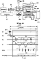
- a navigator echo is, for example, generated by applying a gradient magnetic field pulse for generating the navigator echo between a RF pulse 201 and a series of echo signal train obtaining routine 211 in a multi-shot EPI sequence as illustrated in Fig.4. Such sequence is illustrated in Fig.6. As illustrated in Fig.6, one navigator echo 3021 and 3022 is introduced for every RF pulse 2011 and 2012 irradiation. While assuming that no positional fluctuation of an object to be inspected occurs within a predetermined repetition time 209 or 304, motion of the object to be inspected is estimated based on a change between one navigator echo obtained in one repetition time (TR) and another navigator echo obtained in subsequent another repetition time (TR).
- TR repetition time
- TR navigator echo obtained in subsequent another repetition time
- a navigator echo in a first measurement (illustrated in the drawing in gray) corresponding to shot number 1 is used as a reference and a necessary correction with regard to an object motion is carried out for the data of corresponding actual measurements (207 in Fig.4) based on the changes of the navigator echoes in the following three time unit measurements 304 (shot numbers 2-4) to thereby obtain one piece of image 6011.
- an MR fluoroscopy is known as one of applications of multi-shot EPI.
- Such MR fluoroscopy is illustrated in Fig.5 in which from the beginning of measurement to the end thereof repetitive unit measurement 209 are time to time continued to obtain echo signal trains, and a predetermined number of new echo signal trains which are necessary for reconstructing one piece of image are used while counting back from the latest measurement, for example, in Fig.5 echo signals obtained in the four time unit measurements are used, to reconstruct images for respective moments.
- MR fluoroscopy and navigation echo method In order to correct such an object motion it is conceivable to combine the above mentioned MR fluoroscopy and navigation echo method.
- a navigator echo in a predetermined repetitive unit measurement having a fixed shot number among four repetitive unit measurements having respective shot numbers is used as a reference of phase correction for respective images, for example, a navigator echo in the first repetitive unit measurement (as illustrated in gray in the drawing) is used as illustrated in Fig.8.
- pieces of image 5011 ⁇ 5017 are renewed for every repetition time TR of the unit measurement 304.
- the navigator echo used as a reference is renewed for every four unit measurements counting from the first unit measurement 304 (the renewal timings A, B and C are illustrated in gray in the drawing), therefore, a reference interval for the object motion correction making use of such navigator echo is prolonged to four times of the repetition time (4TR), and thus, notwithstanding a high apparent temporal resolution corresponding to the image renewal interval TR, a sudden change in an animating image is caused for every fourth image and the realtime characteristic thereof is deteriorated.
- an object of the present invention is to provide an MRI method and a device therefor which permits an object motion correction while keeping a high temporal resolution in animating images, and reduces artifacts correspondingly depending on such a high temporal resolution.
- the MRI method and the device therefor is characterized in that, a navigator echo is generated for every irradiation of the RF pulses and is detected, a navigator echo which is served as a reference for correcting phases of the echo signals used for the image reconstruction is successively renewed for every image, and the phases of the echo signals are corrected based on the renewed navigator echo for every image to obtain the same.
- the reference interval for the object motion correction is matched with a renewal interval of consecutive images, thereby an object motion correction is performed while keeping a high temporal resolution of images.
- Such MRI method and device according to the present invention is desirably applied to a method and device where data of images are obtained from echo signal trains which are acquired by repeating a plurality of irradiations of RF pulses, namely, a multi-shot sequence, and can reduce artifacts due to object motion caused between shots.
- At least one navigator echo having zero phase encoding amount is desirably generated additionally for every RF pulse.
- phase differences between a reference navigator echo and other navigator echoes generated and obtained in connection with respective RF pulses are used for correcting phases of the obtained echo signals, thereby artifacts due to object motion are substantially removed.
- the navigator echo is primarily introduced to monitor motions of an object to be inspected with respect to an axis of the navigator echo, therefore, if another navigator echo having different axis is obtained, the object motion in plural directions can be monitored.
- Fig.3 shows a schematic constitution of a typical MRI device to which the present invention is applied.
- the MRI device is provided with a magnet 402 which is designed to generate a static magnetic field around an object 401 to be inspected, a gradient magnetic field coil 403 which is designed to generate a gradient magnetic field in the space of the static magnetic field, an RF coil 404 which is designed to generate a high frequency magnetic field in the magnetic field region and an RF probe 405 which is designed to detect MR signals generated from the object 401 to be inspected.
- a bed 412 is for laying the object 401 to be inspected thereon.
- the gradient magnetic field coil 403 is constituted by gradient field coil units in three axial directions crossing perpendicularly each other and generates respective gradient magnetic fields in response to signals from a gradient magnetic field source 409. With these three axial direction gradient magnetic field coil units 403, three axial direction gradient magnetic fields including slicing direction, phase encoding direction and reading out direction are applied to the space where the object 401 to be inspected is laid. Further, it is not always necessary to match the application axes of the gradient magnetic fields with x, y and z axes of the gradient magnetic field coil units 403.
- the RF coil 404 generates a high frequency magnetic field in a pulse form in response to signals from an RF transmitter unit 410.
- Signals from the RF probe 405 are detected by a signal detection unit 406, and are signal-processed at a signal processing unit 407 or are through calculation converted into image signals. Images are displayed at a display unit 408.
- the gradient magnetic field source 409, the RF transmitter unit 410 and the signal detection unit 406 are controlled by a control unit 411, and its control time chart is generally called as pulse sequence, and in the present invention a pulse sequence for forming animating images is carried out.
- a MR fluoroscopy which is employed for the MRI method according to the present invention is explained with reference to Fig.1.
- a plurality (P times) of image picking-ups 1021, 1022, 1023 ⁇ is carried out in an entire image picking-up time 103.
- Each image picking-up operation is respectively consisted of a multi-shot sequence as illustrated in Fig.6, and, in the present example, a multi-shot of four shots EPI is employed and in each image picking-up operation four times measurements 1011 ⁇ 1014 corresponding to respective shots are performed, for which shot numbers 1-4 are respective assigned in the drawing.
- One piece of image is reconstructed by the echo signals obtained in the four times measurements.
- a first piece of image 1041 is produced by making use of echoes contained in a group of shot numbers 1-4 which are obtained at the time of image picking-up 1021.
- a second piece of image 1042 is produced by making use of a group of echo signals in which echo signals of shot number 1 in the first image picking-up 1021 is renewed by echo signals of shot number 1 obtained in the subsequent image picking-up 1022.
- a third piece of image 1043 is likely produced by making use of a group of echo signals in which echo signals of shot number 2 in the first image picking-up 1021 is renewed by echo signals of shot number 2 in the subsequent image picking-up 1022.
- images are produced by renewing echo signals obtained in the previous shot with echo signals having the same shot number in the new image picking-up, in other words, by successively renewing a part of echo train groups.
- animated images are obtained of an interval corresponding to the measurement repetition time TR.
- a step is introduced in which a navigator echo is generated and detected in every measurement 1011 ⁇ 1014 corresponding to respective shots of RF pulses, and with these navigator echo, phases of echo signals in respective echo trains are corrected which are used for reconstructing respective images.
- the pulse sequence including navigator echoes is prepared by adding a sequence of generating navigator echoes to a multi-shot sequence, in that as illustrated in Fig.6, at first an RF pulse 2011 is irradiated at the same time with the application of a slicing gradient magnetic field Gs 202, subsequently, a gradient magnetic field Gr 301 for generating a navigator echo is applied.
- a navigator echo 3021 is generated which is sampled during time span 303 to obtain data expanding along time axis.
- the phase encoding amount of the navigator echo is zero, because no phase encoding gradient magnetic field is applied thereto.
- Portions 2111 and 2112 in Fig.6 surrounded by solid lines corresponds to a process 211 in the multi-shot EPI sequence shown in Fig.4, wherein offset reading out gradient magnetic field Gr 205 as well as a gradient magnetic field Gp 203 which provides an offset to the phase encoding amount are applied, and subsequently a readout gradient magnetic field Gr 206 which successively alternates and phase encoding gradient magnetic field Gp 204 in synchronism therewith are applied.
- echo signals 207 of respective phase encodes are generated sequentially, which are respectively sampled during respective time spans 208 to obtain data expanding along time axis.
- a sequence including the RF pulse irradiation and the process 2111 is repeated with the repetition time TR 304 while varying the offset amount of the phase encoding gradient magnetic field Gp 203 until completing measurement of echo signals of entire phase encoding amount.
- the encoding amount (KY) in the phase encoding direction is 256 and the number of echo signals (number of echo signals M in an echo train) measured in connection with one RF pulse irradiation is 64
- a multi-shot EPI having sequence shot number N (number of repetitions) of 4 is established.
- data point number (KX) in the readout direction is selected, for example, to be 256.
- a number of navigator echoes corresponding to shot number (N) x image picking-up number P is obtained.
- Each of the navigator echoes is expressed as V (kx, pn), wherein kx represents data point number in the readout direction and satisfies the inequation 1 ⁇ kx ⁇ KX, and pn represents a navigator echo obtained at nth shot in pth image picking-up and satisfies the inequations 1 ⁇ p ⁇ P and 1 ⁇ n ⁇ N.
- mth (1 ⁇ m ⁇ M) echo signal S obtained at nth shot in pth image picking-up is expressed as S(kx, pn, m) and of which object motion is corrected based on the phase information of the corresponding navigator echo V(kx, pn) (having the same pn as the echo signals).
- a reference navigator echo for determining phase information for respective other navigator echoes is not fixed to one having a specific shot number and is successively shifted.
- navigator echoes of respective shots serve at one instance as object motion monitoring navigator echoes and serve at another instance as a reference navigator echo.
- upper halves of the respective shots are illustrated in gray and the lower halves are in white which indicates that respective navigator echoes can be served as a reference as well as a monitor.
- a navigator echo in the oldest (most previous) shot among a group of measurements used for an image reconstruction is used as a reference navigator echo.
- a reference navigator echo is successively renewed, therefore, the reference interval for correcting object motion is renewed for every repetition time TR, in other words, for every repetitive unit measurement interval and further, in the present embodiment, for every image renewal interval, thereby an object motion correction with an accuracy corresponding to the improved temporal resolution is carried out, artifacts due to the object motion is reduced and desirable images can be obtained.
- phase differences between a reference navigator echo and other object motion monitoring navigator echoes are directly determined and the phases of the corresponding echo signals are corrected based on the thus determined phase differences, namely, a phase correction method in which phase differences are determined by making use of data of k space of navigator echoes and the phase correction of the echo signals is performed in k space is explained hereinbelow.
- phase differences ⁇ is, for example, determined through the following calculations.
- the ordinal numbers p of image picking-ups in V(kx, 1) and V(kx, n) do not necessarily match each other, the symbols corresponding to the ordinal numbers of image picking-ups are omitted in the followings for simplifying the explanation.
- phase shift map C(kx, n) expressed by a real portion and an imaginary portion of both navigator echo signals is determined.
- C(kx, n)] re[V(kx, n)] ⁇ re[V(kx, 1)]/
- im[C(kx, n)] im[V(kx, n)] ⁇ re[V(kx, 1)]/
- phase differences ⁇ are determined for every data point number (kx ; time axis) in the readout direction.
- phase differences of echo signals S are corrected based on these determined phase differences ⁇
- the phase differences ⁇ as determined through the above calculations contain phase variations rotating around a principal value and noises. Therefore, it is preferable to apply a processing of correcting such phase variations and noises contained in the phase differences ⁇ prior to using the same for the phase correction of the echo signal (kx, n, m).
- phase differences ⁇ Although noises in the phase differences ⁇ , of which phase variations rotating around a principle value are removed, is decreased, the phase differences still contain some noise components which disturb calculation for the phase shift amount thereof. These noise components can be suppressed, for example, through a Median filter, a Butter-Worth filter and a filtering processing such as a local averaging processing to thereby obtain a general or non-local variation of phase shift.
- phase shift map C'(kx, n) By making use of thus corrected phase shift map C'(kx, n) echo signals S(kx, n, m) are corrected, and echo signals S'(kx, n, m) of which phase shift are corrected are obtained.
- the phase shift correction is performed for all of echo signals S(kx, n, m) having the same kx and n as those in the correct phase shift map C' (kx, n) according to the following calculation.
- phase shift corrected echo signals S'(kx, n, m) Even if an object to be inspected moves during the time when performing a group of measurements necessary for obtaining one piece of image, the phase variations due to the motion can be corrected and images with no artifacts due to object motion can be obtained.
- the method according to the present embodiment is particularly effective for a case where the object to be inspected undergoes a large motion more than one pixel.
- the images are thus reconstructed with such object motion correction processing while renewing the reference navigator echo for every image to be reconstructed.
- phase correction method in which phase differences are determined by making use of data of k space of navigator echoes and the phase correction of the echo signals is performed in k space is explained.
- methods of phase correction using navigator echoes applicable to the present invention are not limited to one as applied to the above embodiment.
- Conventional object motion correcting methods in which phase differences are determined from navigator echo signals after Fourier-transformed can be applied.
- a method in which navigator echoes are Fourier-transformed, phase differences between respective Fourier-transformed navigator echoes are determined, and the phases of echo signals Fourier-transformed on the same axis as the Fourier-transformed navigator echoes are corrected in an image space, can be applied, which method consumes time because of a many number of times of the Fourier transformations, but which method is capable of correcting precisely a small object motion, therefore, is, in particular, effective for a sequence such as diffusion imaging in which even a very small motion will cause artifacts.
- phase correction method in which profiles are determined by Fourier-transforming navigator echoes, phase differences of navigator echoes are determined based on a correlation of the profile positional shiftings between respective Fourier-transformed navigator echoes, and the phases of the corresponding echo signals are corrected in k space, can be also applied.
- MR fluoroscopy which are applicable to the present invention are not limited to one explained in connection with the above embodiment, and several modifications can be acceptable.
- a method of MR fluoroscopy as disclosed in JP-A-6-343621(1994) can be applied to the present invention, in which method echo signal measurement order is controlled in such a manner that among a plurality of measured echo signals necessary for reconstructing one piece of image, only predetermined measured echo signals having a specific phase information (for example, data of a low spatial frequency region) are completely replaced for every reconstruction of images.
- Fig.2 illustrates such measurement method in which, when picking-up images by dividing k space, for example, into three regions 21, 22 and 23, measurement of the region 22 is repeated more frequently than the measurement of other regions, and for successively renewed images 51, 52 and 53, data of the region 22 are always replaced by newly measured data thereof. Namely, at first, data for regions 21, 22 and 23 are successively collected to reconstruct the image 51, in the subsequent data collection new data of regions 22 and 21 are successively collected to reconstruct the image 52 together with the data of the region 23 which was used immediately before for reconstructing the image 51. In further subsequent data collection new data of the regions 22 and 23 are successively collected to reconstruct the image 53 together with the data of the region 21 used immediately before for reconstructing the image 52.
- the region which contributes most for variations of images in association with lapse of time is the low spatial frequency region
- the low spatial frequency region is selected as the region 22 of which data are always renewed, thereby animating images having a desirable quality, of which temporal resolution of the reproduced images are scarcely deteriorated, can be obtained, even with a low apparent temporal resolution (2TR).
- the generation and detection of a navigator echo is added for each of the measurements, and a navigator echo which is obtained, for example, in the earliest measurement is selected as a reference navigator echo for every image and the phases of the measurement data of other regions are corrected based on the reference navigator echo.
- a navigator echo which is obtained, for example, in the earliest measurement is selected as a reference navigator echo for every image and the phases of the measurement data of other regions are corrected based on the reference navigator echo.
- the navigator echo obtained in the measurement of the region 21 is selected as the reference and the phases of measurement data of the other regions are corrected
- the navigator echo obtained in the measurement of the region 23 is selected as the reference and the phases of the measurement data of other regions are corrected.
- the reference interval in other words resolution of the phase correction is matched with the temporal resolution 2TR for the images.
- a navigator echo obtained in the earliest measurement of the necessary measurements for reconstructing one piece of image can be selected as the reference navigator echo as in the above embodiment.
- the present invention does not limited to the above embodiment, and, for example, the navigator echo obtained in the measurement of the region 22 of which measurement data are always renewed can be used as the reference navigator echo.
- a navigator echo can be added in the prescanning sequence itself and of which added navigator echo can be also used as a reference navigator echo.
- an EPI sequence is exemplified as the standard sequence of the MR fluoroscopy.
- the standard sequence of the MR fluoroscopy is not limited to such sequence, and, in principle, any sequences, in which echo signals for reconstructing one piece of image are obtained by repeating shots of RF pulses, can be used. Examples of such sequences are, for example, burst imaging, hybrid burst imaging, gradient echo sequence, divided high speed gradient echo sequence, three dimensional (3D)-EPI, echo volumer, spiral imaging, EPI type spectroscopy imaging and diffusion imaging.
- a single navigator echo only in readout direction is introduced for every one shot of RF pulse.
- respective navigator echoes in readout direction and phase encoding direction can be introduced.
- an orbital navigator echo which is generated by applying gradient magnetic fields of which phases are shifted by 90° in two crossing directions, can be used. Thereby, phase information of a plane formed by the two axes can be corrected.
- phase encoding amount of the navigator echo is not limited to zero, if the phase encoding amount thereof is in a same condition.
- the present invention is not limited to the contents disclosed in connection with the embodiments, but can take several modifications in view of the gist of the present invention.
- a navigation echo method to an MR fluoroscopy
- a reference navigator echo is successively renewed for every one of images which constitute animating images
- the positional information of the object to be inspected during the respective image picking-ups is reflected on respective images and a possible object motion of the object to be inspected is corrected based on the reflected positional information, thereby artifacts due to the object motion is reduced while keeping a high temporal resolution.
Landscapes
- Physics & Mathematics (AREA)
- Health & Medical Sciences (AREA)
- General Health & Medical Sciences (AREA)
- Nuclear Medicine, Radiotherapy & Molecular Imaging (AREA)
- Radiology & Medical Imaging (AREA)
- Engineering & Computer Science (AREA)
- Signal Processing (AREA)
- High Energy & Nuclear Physics (AREA)
- Condensed Matter Physics & Semiconductors (AREA)
- General Physics & Mathematics (AREA)
- Magnetic Resonance Imaging Apparatus (AREA)
Abstract
Description
when
Claims (14)
- A magnetic resonance imaging method in which after irradiating RF pulses (201, 2011, 2012) of magnetic resonance frequencies into an object to be inspected, a sequence of detecting the echo signals (207) sequentially and a step of reconstructing an image by making use of the obtained echo signals are repeated in parallel, and subsequent images are obtained by successively renewing a part of the echo signals used for reconstructing the previous image, characterized in that, a navigator echo (3021, 3022) is generated for every irradiation of the RF pulses (2011, 2012) and is detected, and a navigator echo which is served as a reference for correcting phases of the echo signals used for the image reconstruction is successively renewed for every image, and the phases of the echo signals are corrected based on the renewed navigator echo for every image to obtain the same.
- A magnetic resonance imaging method according to claim 1, further comprising a step of forming an animating image from a plurality of successively reconstructed images.
- A magnetic resonance imaging method comprising the steps of :irradiating a RF pulse (201, 2011, 2012) of magnetic resonance frequencies toward a predetermined slicing surface of an object to be inspected, and then detecting an echo signal group (207) sequentially produced in association with the irradiation of the RF pulse (201, 2011, 2012) ;reconstructing a piece of image of the predetermined slicing surface by making use of a plurality of echo signal groups (207) which are acquired by repeating said echo signal group detecting step in a plurality of times ;further reconstructing a subsequent piece of image of the predetermined slicing surface by making use of a part of the plurality of echo signal groups which is used for the previous image reconstruction and an echo signal group which is acquired by performing subsequently said echo signal group detecting step at least one time ; andrepeating said further step of reconstructing a subsequent piece of image while renewing a part of the plurality of echo signal groups used for the image reconstruction, wherein the magnetic resonance paging method further comprising the steps of :introducing in each of said echo signal group detecting steps at least one navigator echo (3021, 3022) for each of the echo signal groups ;role-assigning one of the respective navigator echoes introduced for a plurality of echo signal groups which are used for reconstructing a piece of image as a reference navigator echo exclusively for the reconstruction of the piece of image and the remaining navigator echoes as monitor navigator echoes ;determining phase differences between the reference navigator echo and the monitor navigator echoes of which roles are assigned exclusively for the reconstruction of the piece of image, and correcting the phases of echo signal groups to which the respective monitor navigator echoes belong based on the determined phase differences ; andselecting for a successive image reconstruction a new reference navigator echo other than the navigator echo which is used as the reference navigator echo in the previous image reconstruction among respective navigator echoes for a plurality of echo signal groups which are used for the successive image reconstruction.
- A magnetic resonance imaging method according to claim 3, further comprising a step of forming an animating image from a plurality of successively reconstructed images.
- A magnetic resonance imaging method according to claim 3, wherein the navigator echoes introduced into said respective echo signal group detecting steps are introduced prior to the respective echo signal groups.
- A magnetic resonance imaging method according to claim 3, wherein the navigator echoes introduced into said respective echo signal group detecting steps are introduced in readout direction with its encoding amount of zero.
- A magnetic resonance imaging method according to claim 3, wherein the navigator echoes introduced into said respective echo signal group detecting steps include one in readout direction and another in phase encoding direction respectively.
- A magnetic resonance imaging method according to claim 3, wherein the navigator echoes introduced into said respective echo signal group detecting steps are an orbital navigator echo which is generated by applying two gradient magnetic fields in perpendicular directions of which phases are shifted by 90°.
- A magnetic resonance imaging method according to claim 3, further comprising the steps of ;prescanning the predetermined slicing surface prior to said echo signal group detecting step for adjusting uniformity of the static magnetic field ;introducing at least one navigator echo into said prescanning step ; androle-assigning the navigator echo introduced into said prescanning step as a reference navigator echo for said successive reconstruction step of the one piece of image.
- A magnetic resonance imaging method according to claim 3, wherein among the navigator echoes belonging to the respective plurality of echo signal groups which are used for reconstructing one piece of image, one of the navigator echoes which belongs to an echo signal group generated from a specific region on the predetermined slicing surface is assigned as a reference navigator echo.
- A magnetic resonance imaging method according to claim 10, wherein the specific region on the predetermined slicing surface is a low spatial frequency region.
- A magnetic resonance imaging method according to claim 11, wherein the echo signal group generated from the specific region on the predetermined slicing surface is renewed for every reconstruction of one piece of image.
- A magnetic resonance imaging device comprising :means (404, 410, 411) for repeadedly irradiating RF pulses (201, 2011, 2012) of magnetic resonance frequencies at a predetermined interval onto an object (401) to be inspected and placed in a static magnetic field ;means (403, 409, 411) for applying gradient magnetic fields (Gs, Gp, Gr) in the space of the static magnetic field surrounding the object (401) to be inspected so as to acquire an echo signal group (207) and at least one navigator echo (3021, 3022) from a predetermined region on a predetermined slicing surface of the object (401) to be inspected in response the respective irradiation of the RF pulses (201, 2011, 2012) from said RF pulse irradiation means (404, 410, 411) ;means (405, 406, 411) for detecting the echo signal groups (207) and the navigator echoes (3021, 3022) belonging to the respective echo signal groups (207) which are produced in response to the application of the gradient magnetic fields (Gs, Gp, Gr) from said gradient magnetic field application means (403, 409, 411) ; andmeans (407, 411) for reconstructing one piece of image of the predetermined slicing surface by making use the plurality of echo signal groups (207) acquired in said echo detecting means (405, 406, 411), wherein said image reconstructing means (407, 411) reconstruct subsequent one piece of image of the predetermined slicing surface by making use of a part of the plurality of echo signal groups (207) which are used for reconstructing the previous one piece of image and at least one echo signal group (207) newly acquired from said echo detecting means (405, 406, 411), during the respective image reconstructions one of the navigator echoes (3021, 3022) each belonging to one of the plurality of echo signal groups (207) which are used for each of the image reconstructions is assigned as a reference navigator echo, then phase differences between the thus assigned reference navigator echo (3021, 3022) and other remaining navigator echoes (3021, 3022) are determined, the phases of the plurality of echo signal groups (207) which are used for the image reconstruction are corrected based on the determined respective phase differences, and further the reference navigator echo (3021, 3022) which is used for the phase correction of the respective plurality of echo signal groups (207) is renewed for every image reconstruction.
- A magnetic resonance imaging device according to claim 13 further comprising, means (407, 408, 411) for forming an animating image from a plurality of images successively reconstructed and for displaying the same.
Applications Claiming Priority (3)
| Application Number | Priority Date | Filing Date | Title |
|---|---|---|---|
| JP284945/97 | 1997-10-17 | ||
| JP28494597A JP3815585B2 (en) | 1997-10-17 | 1997-10-17 | Magnetic resonance imaging system |
| JP28494597 | 1997-10-17 |
Publications (2)
| Publication Number | Publication Date |
|---|---|
| EP0909958A2 true EP0909958A2 (en) | 1999-04-21 |
| EP0909958A3 EP0909958A3 (en) | 2000-03-29 |
Family
ID=17685110
Family Applications (1)
| Application Number | Title | Priority Date | Filing Date |
|---|---|---|---|
| EP98116655A Ceased EP0909958A3 (en) | 1997-10-17 | 1998-09-03 | Use of navigator echoes for the correction of motion artifacts in MRI |
Country Status (4)
| Country | Link |
|---|---|
| US (1) | US6118273A (en) |
| EP (1) | EP0909958A3 (en) |
| JP (1) | JP3815585B2 (en) |
| CN (1) | CN1231177C (en) |
Cited By (10)
| Publication number | Priority date | Publication date | Assignee | Title |
|---|---|---|---|---|
| DE10029585A1 (en) * | 2000-06-15 | 2002-01-03 | Siemens Ag | Method for operating a magnetic resonance imaging device has compensation for patient movement between successive images so that more precise medical diagnostics can be made |
| DE10044424A1 (en) * | 2000-09-08 | 2002-04-04 | Siemens Ag | Magnetic resonance imaging device for obtaining NMR navigator echoes with little disturbance of the longitudinal magnetization |
| DE10056874A1 (en) * | 2000-11-16 | 2002-05-29 | Siemens Ag | Magnetic resonance imaging of parts of the human brain with the inventive method allowing positional changes of an examination area to be precisely detected and corrected |
| EP1209481A1 (en) * | 2000-10-18 | 2002-05-29 | Philips Corporate Intellectual Property GmbH | Method of correcting phase errors in real-time MRI |
| DE10105388A1 (en) * | 2001-02-06 | 2002-08-22 | Siemens Ag | Method for operating a magnetic resonance device |
| WO2004034075A1 (en) * | 2002-10-11 | 2004-04-22 | Koninklijke Philips Electronics N.V. | Magnetic resonance method and device |
| DE102006002982A1 (en) * | 2006-01-21 | 2007-08-09 | Bruker Biospin Mri Gmbh | Method for generating MR (= magnetic resonance) images of a moving subarea of an object |
| DE102006017049B3 (en) * | 2006-04-11 | 2008-02-14 | Siemens Ag | Method of recording magnetic resonance image data and magnetic resonance device |
| DE102004017852B4 (en) * | 2004-04-13 | 2008-11-27 | Siemens Ag | Motion-corrected multi-shot method for diffusion-weighted imaging in magnetic resonance imaging |
| DE10330926B4 (en) * | 2003-07-08 | 2008-11-27 | Siemens Ag | Method for the absolute correction of B0 field deviations in magnetic resonance tomography imaging |
Families Citing this family (28)
| Publication number | Priority date | Publication date | Assignee | Title |
|---|---|---|---|---|
| JP4197059B2 (en) * | 1997-10-17 | 2008-12-17 | 株式会社日立メディコ | Nuclear magnetic resonance imaging system |
| DE69938713D1 (en) * | 1998-11-25 | 2008-06-26 | Koninkl Philips Electronics Nv | METHOD AND DEVICE OF MAGNETIC RESONANCE |
| US6885885B1 (en) * | 1999-05-26 | 2005-04-26 | Hitachi Medical Corporation | Magnetic resonance imaging method and device |
| JP2001095775A (en) * | 1999-10-01 | 2001-04-10 | Hitachi Medical Corp | Nuclear magnetic resonance imaging apparatus and procedure |
| JP3454760B2 (en) * | 1999-10-22 | 2003-10-06 | ジーイー・メディカル・システムズ・グローバル・テクノロジー・カンパニー・エルエルシー | Phase distribution measuring method and apparatus, phase correcting method and apparatus, and magnetic resonance imaging apparatus |
| US6424153B1 (en) * | 1999-11-23 | 2002-07-23 | Koninklijke Philips Electronics, N.V. | On-the-fly removal of data inconsistency with k-space oversampling and demodulation in MRI acquisitions |
| JP3858194B2 (en) * | 2001-04-04 | 2006-12-13 | ジーイー・メディカル・システムズ・グローバル・テクノロジー・カンパニー・エルエルシー | MRI equipment |
| JP3878429B2 (en) * | 2001-04-05 | 2007-02-07 | ジーイー・メディカル・システムズ・グローバル・テクノロジー・カンパニー・エルエルシー | MRI equipment |
| US6518759B2 (en) | 2001-04-09 | 2003-02-11 | Mayo Foundation For Medical Education And Research | Motion correction of magnetic resonance images |
| US6771068B2 (en) | 2001-05-10 | 2004-08-03 | General Hospital Corporation | System and method for providing real-time motion correction by utilizing navigators |
| JP4443079B2 (en) | 2001-09-13 | 2010-03-31 | 株式会社日立メディコ | Magnetic resonance imaging apparatus and RF receiving coil for magnetic resonance imaging apparatus |
| JP4141147B2 (en) * | 2002-02-01 | 2008-08-27 | 株式会社日立メディコ | Magnetic resonance imaging system |
| CN100553086C (en) * | 2004-03-15 | 2009-10-21 | 株式会社日立医药 | Power conversion device, inverter X-ray high voltage device, X-ray fluoroscopy camera device, X-ray CT device, MRI device |
| CN100392424C (en) * | 2004-11-15 | 2008-06-04 | 华东师范大学 | A Method for Recombining Echo Data in a Graphical Pulse Sequence Compiler |
| US7847546B2 (en) * | 2005-07-27 | 2010-12-07 | Hitachi Medical Corporation | Magnetic resonance imaging apparatus |
| US7358732B2 (en) * | 2005-10-24 | 2008-04-15 | The General Hospital Corporation | System, method, software arrangement and computer-accessible medium for providing real-time motion correction by utilizing clover leaf navigators |
| CN101470178B (en) * | 2007-12-29 | 2013-06-05 | 西门子(中国)有限公司 | Method and apparatus for restraining residual motion artifact |
| DE102010001703B4 (en) * | 2010-02-09 | 2012-03-08 | Bruker Biospin Mri Gmbh | Compensation for MR measurements on moving objects by adjusting the measurement conditions |
| DE102011006230B4 (en) | 2011-03-28 | 2013-01-24 | Siemens Aktiengesellschaft | Pixel-wise correction of phase information in MR images using a navigator signal |
| CN104395773B (en) * | 2012-03-26 | 2017-08-15 | 皇家飞利浦有限公司 | Through the omniselector of plane |
| DE102014210471B4 (en) | 2014-06-03 | 2018-11-08 | Siemens Healthcare Gmbh | A method of performing a magnetic resonance examination with a prospective motion correction and magnetic resonance system therefor |
| JP2016198392A (en) * | 2015-04-13 | 2016-12-01 | 東芝メディカルシステムズ株式会社 | Magnetic resonance imaging system |
| US10823806B2 (en) * | 2017-11-22 | 2020-11-03 | Siemens Healthcare Gmbh | Magnetic resonance imaging using dataset undersampling |
| US10809341B1 (en) * | 2019-04-19 | 2020-10-20 | Canon Medical Systems Corporation | Readout-segmented echo planar imaging with k-space averaging |
| CN113625209B (en) * | 2020-05-09 | 2024-02-27 | 上海联影医疗科技股份有限公司 | Method, device and computer equipment for determining frequency drift of magnetic resonance system |
| JP7539255B2 (en) * | 2020-05-21 | 2024-08-23 | 富士フイルムヘルスケア株式会社 | Magnetic Resonance Imaging |
| CN113917380B (en) * | 2020-07-10 | 2025-02-25 | 佳能医疗系统株式会社 | Magnetic resonance imaging apparatus and magnetic resonance imaging method |
| CN112014781B (en) * | 2020-09-02 | 2021-04-20 | 无锡鸣石峻致医疗科技有限公司 | Phase correction method and device for magnetic resonance echo signals, computer equipment and computer readable storage medium |
Family Cites Families (11)
| Publication number | Priority date | Publication date | Assignee | Title |
|---|---|---|---|---|
| US4684891A (en) * | 1985-07-31 | 1987-08-04 | The Regents Of The University Of California | Rapid magnetic resonance imaging using multiple phase encoded spin echoes in each of plural measurement cycles |
| JPH0632643B2 (en) * | 1986-04-11 | 1994-05-02 | 株式会社日立メディコ | Nuclear magnetic resonance imaging device |
| US4830012A (en) * | 1987-08-14 | 1989-05-16 | Duke University | High speed NMR imaging method and apparatus |
| US5270654A (en) * | 1991-07-05 | 1993-12-14 | Feinberg David A | Ultra-fast multi-section MRI using gradient and spin echo (grase) imaging |
| JPH05154130A (en) * | 1991-12-06 | 1993-06-22 | Hitachi Ltd | Body motion artifact eliminating method |
| JP3283632B2 (en) * | 1993-06-04 | 2002-05-20 | 株式会社日立製作所 | Nuclear magnetic resonance equipment |
| JPH0775627A (en) * | 1993-06-11 | 1995-03-20 | Hitachi Ltd | Body motion tracking measurement method in magnetic resonance diagnostic apparatus |
| JP2713160B2 (en) * | 1994-03-31 | 1998-02-16 | 株式会社島津製作所 | MR imaging device |
| US5800354A (en) * | 1994-11-23 | 1998-09-01 | U.S. Phillips Corporation | Method of and device for magnetic resonance imaging |
| US5539312A (en) * | 1995-02-02 | 1996-07-23 | Mayo Foundation For Medical Education And Research | Detection and measurement of motion during NMR imaging using orbital navigator echo signals |
| DE19524184B4 (en) * | 1995-07-03 | 2006-08-17 | Siemens Ag | Pulse sequence for rapid imaging in magnetic resonance imaging |
-
1997
- 1997-10-17 JP JP28494597A patent/JP3815585B2/en not_active Expired - Fee Related
-
1998
- 1998-09-03 EP EP98116655A patent/EP0909958A3/en not_active Ceased
- 1998-09-09 US US09/149,121 patent/US6118273A/en not_active Expired - Lifetime
- 1998-10-16 CN CN98124131.XA patent/CN1231177C/en not_active Expired - Fee Related
Cited By (21)
| Publication number | Priority date | Publication date | Assignee | Title |
|---|---|---|---|---|
| DE10029585C2 (en) * | 2000-06-15 | 2002-04-18 | Siemens Ag | Method for operating a magnetic resonance device with detection of changes in position |
| DE10029585A1 (en) * | 2000-06-15 | 2002-01-03 | Siemens Ag | Method for operating a magnetic resonance imaging device has compensation for patient movement between successive images so that more precise medical diagnostics can be made |
| US6556008B2 (en) | 2000-06-15 | 2003-04-29 | Siemens Aktiengesellschaft | Method for operating a magnetic resonance imaging apparatus ensuring coincidence of images obtained in different examinations with respectively different positions of a subject |
| US6683453B2 (en) | 2000-09-08 | 2004-01-27 | Siemens Aktiengesellschaft | Magnetic resonance apparatus for obtaining NMR navigator echoes with slight disturbance of the longitudinal magnetization |
| DE10044424A1 (en) * | 2000-09-08 | 2002-04-04 | Siemens Ag | Magnetic resonance imaging device for obtaining NMR navigator echoes with little disturbance of the longitudinal magnetization |
| DE10044424C2 (en) * | 2000-09-08 | 2002-12-05 | Siemens Ag | Method for operating a magnetic resonance tomography device, wherein a spatially resolved navigator rod is obtained for position monitoring of an object to be examined |
| EP1209481A1 (en) * | 2000-10-18 | 2002-05-29 | Philips Corporate Intellectual Property GmbH | Method of correcting phase errors in real-time MRI |
| US6466015B2 (en) | 2000-10-18 | 2002-10-15 | Koninklijke Philips Electronics N.V. | Phase correction method for real-time MR imaging |
| DE10056874A1 (en) * | 2000-11-16 | 2002-05-29 | Siemens Ag | Magnetic resonance imaging of parts of the human brain with the inventive method allowing positional changes of an examination area to be precisely detected and corrected |
| DE10056874C2 (en) * | 2000-11-16 | 2003-02-06 | Siemens Ag | Method for operating a magnetic resonance device in which changes in position are detected by means of orbital navigator echoes |
| DE10105388A1 (en) * | 2001-02-06 | 2002-08-22 | Siemens Ag | Method for operating a magnetic resonance device |
| US6771998B2 (en) | 2001-02-06 | 2004-08-03 | Siemens Aktiengesellschaft | Method for the operation of a magnetic resonance apparatus |
| DE10105388B4 (en) * | 2001-02-06 | 2007-05-24 | Siemens Ag | Method for adapting the spatial coding during operation of a magnetic resonance apparatus |
| WO2004034075A1 (en) * | 2002-10-11 | 2004-04-22 | Koninklijke Philips Electronics N.V. | Magnetic resonance method and device |
| US7239138B2 (en) | 2002-10-11 | 2007-07-03 | Koninklijke Philips Electronics N.V. | Magnetic resonance method and device |
| DE10330926B4 (en) * | 2003-07-08 | 2008-11-27 | Siemens Ag | Method for the absolute correction of B0 field deviations in magnetic resonance tomography imaging |
| DE102004017852B4 (en) * | 2004-04-13 | 2008-11-27 | Siemens Ag | Motion-corrected multi-shot method for diffusion-weighted imaging in magnetic resonance imaging |
| DE102006002982A1 (en) * | 2006-01-21 | 2007-08-09 | Bruker Biospin Mri Gmbh | Method for generating MR (= magnetic resonance) images of a moving subarea of an object |
| DE102006002982B4 (en) * | 2006-01-21 | 2009-10-29 | Bruker Biospin Mri Gmbh | Magnetic resonance i.e. nuclear magnetic resonance, image generating method for use in clinical applications, involves phase-correcting data of measurements based on motion conditions to keep positions of partial area in stationary state |
| DE102006017049B3 (en) * | 2006-04-11 | 2008-02-14 | Siemens Ag | Method of recording magnetic resonance image data and magnetic resonance device |
| US7417427B2 (en) | 2006-04-11 | 2008-08-26 | Siemens Aktiengesellschaft | Magnetic resonance data acquisition method and apparatus |
Also Published As
| Publication number | Publication date |
|---|---|
| EP0909958A3 (en) | 2000-03-29 |
| JPH11113878A (en) | 1999-04-27 |
| CN1216242A (en) | 1999-05-12 |
| US6118273A (en) | 2000-09-12 |
| CN1231177C (en) | 2005-12-14 |
| JP3815585B2 (en) | 2006-08-30 |
Similar Documents
| Publication | Publication Date | Title |
|---|---|---|
| US6118273A (en) | Magnetic resonance imaging method and device therefor | |
| US10634753B2 (en) | MR imaging with motion detection | |
| US6541970B1 (en) | Nuclear magnetic resonance imaging method and device | |
| EP2496954B1 (en) | Mr imaging using navigators | |
| US6777934B2 (en) | Magnetic resonance imaging method and apparatus | |
| JP4612000B2 (en) | Magnetic resonance imaging system | |
| EP1472978A1 (en) | Magnetic resonance imaging method and apparatus | |
| JP4072879B2 (en) | Nuclear magnetic resonance imaging system | |
| US6404196B1 (en) | Method for correction of MRI motion artifacts and main field fluctuation | |
| US6927576B2 (en) | Magnetic resonance signal acquiring apparatus and magnetic resonance imaging apparatus | |
| US6728568B1 (en) | Magnetic resonance imaging method and device | |
| US6885885B1 (en) | Magnetic resonance imaging method and device | |
| JP2952228B1 (en) | Continuous MRI image reconstruction method and apparatus | |
| JP4330247B2 (en) | Nuclear magnetic resonance imaging system | |
| US5539311A (en) | Method for reducing artifacts in magnetic resonance imaging | |
| JP4390328B2 (en) | Magnetic resonance imaging system | |
| JP2002085376A (en) | Nuclear magnetic resonance imaging device and method | |
| JP4068114B2 (en) | Magnetic resonance imaging system | |
| WO2001024695A1 (en) | Nuclear magnetic resonance imaging device and method | |
| EP4679122A1 (en) | Gradient echo imaging with compensation of geometric distortions | |
| JPH09289980A (en) | Magnetic resonance imaging system | |
| CN111435156A (en) | Method for obtaining operating parameters, storage medium and magnetic resonance apparatus |
Legal Events
| Date | Code | Title | Description |
|---|---|---|---|
| PUAI | Public reference made under article 153(3) epc to a published international application that has entered the european phase |
Free format text: ORIGINAL CODE: 0009012 |
|
| AK | Designated contracting states |
Kind code of ref document: A2 Designated state(s): DE FR GB NL |
|
| AX | Request for extension of the european patent |
Free format text: AL;LT;LV;MK;RO;SI |
|
| PUAL | Search report despatched |
Free format text: ORIGINAL CODE: 0009013 |
|
| AK | Designated contracting states |
Kind code of ref document: A3 Designated state(s): AT BE CH CY DE DK ES FI FR GB GR IE IT LI LU MC NL PT SE |
|
| AX | Request for extension of the european patent |
Free format text: AL;LT;LV;MK;RO;SI |
|
| 17P | Request for examination filed |
Effective date: 20000922 |
|
| AKX | Designation fees paid |
Free format text: DE FR GB NL |
|
| 17Q | First examination report despatched |
Effective date: 20040524 |
|
| APBN | Date of receipt of notice of appeal recorded |
Free format text: ORIGINAL CODE: EPIDOSNNOA2E |
|
| APBR | Date of receipt of statement of grounds of appeal recorded |
Free format text: ORIGINAL CODE: EPIDOSNNOA3E |
|
| APAF | Appeal reference modified |
Free format text: ORIGINAL CODE: EPIDOSCREFNE |
|
| APBT | Appeal procedure closed |
Free format text: ORIGINAL CODE: EPIDOSNNOA9E |
|
| STAA | Information on the status of an ep patent application or granted ep patent |
Free format text: STATUS: THE APPLICATION HAS BEEN REFUSED |
|
| 18R | Application refused |
Effective date: 20061212 |