JP4072879B2 - Nuclear magnetic resonance imaging system - Google Patents
Nuclear magnetic resonance imaging system Download PDFInfo
- Publication number
- JP4072879B2 JP4072879B2 JP33586398A JP33586398A JP4072879B2 JP 4072879 B2 JP4072879 B2 JP 4072879B2 JP 33586398 A JP33586398 A JP 33586398A JP 33586398 A JP33586398 A JP 33586398A JP 4072879 B2 JP4072879 B2 JP 4072879B2
- Authority
- JP
- Japan
- Prior art keywords
- signal
- coil
- magnetic resonance
- echo
- navigation
- Prior art date
- Legal status (The legal status is an assumption and is not a legal conclusion. Google has not performed a legal analysis and makes no representation as to the accuracy of the status listed.)
- Expired - Fee Related
Links
Images


Landscapes
- Magnetic Resonance Imaging Apparatus (AREA)
Description
【0001】
【発明の属する技術分野】
本発明は、被検体中の水素や燐等からの核磁気共鳴(以下、NMRという)信号を測定し、核の密度分布や緩和時間分布等を映像化する核磁気共鳴撮影装置(以下、MRI装置という)に関し、特に体動補正用のナビゲーションエコーの付加を伴うMRI装置に関する。
【0002】
【従来の技術】
MRIでは、NMR現象によって被検体組織を構成する原子核スピンから発生するNMR信号を計測する際に、信号に位置情報を付与するために傾斜磁場を印加する。この傾斜磁場として、スライスエンコード方向、位相エンコード方向、周波数エンコード方向の3軸方向の傾斜磁場が用いられ、これら傾斜磁場によってエンコードされた信号をフーリエ変換することにより2次元或いは3次元画像として再構成することができる。
【0003】
このようなMRIによる撮影中に、被検体が動くと画像に大きなアーチファクトが生じることが知られている。これを体動アーチファクトという。この体動アーチファクトが発生する理由は、本来所定の計測点にある所定の位相エンコード量が与えられるべきところが、動きによりそのエンコード量が他の計測点に印加されることとなり、被検体の動きの前後で各取得エコーの位相が変化し、この変化したエコーを含めて位相エンコード方向(またはスライスエンコード方向)にフーリエ変換するために生じる。
【0004】
この体動アーチファクトを除去する手法としてナビゲーションエコーを利用した撮影法が提案されている(「ナビゲータを用いた高速インターリーブエコープレナーイメージング:4テスラにおける高解像度解剖学的および機能的画像」MAGNETIC RESONANCE IN MEDICINE, 35:895-902, June 1996, Seong-Gi Kim et al)。この手法では、撮影シーケンスを繰り返すときに、例えばその繰り返し毎に本来の計測エコー(NMR信号)とは別個に位相エンコード量0のエコー信号を発生させて、これをナビゲーションエコーとし、繰り返し毎のナビゲーションエコーの位相の変化から、繰り返しの間に生じた体動による信号の位相変化を推定し、補正する。
【0005】
【発明が解決しようとする課題】
しかしナビゲーションエコーを用いた撮影方法では、撮像視野内に局所的な体動があったときに対応できない場合がある。例えば図10(a)に示すように複数の受信コイルからなるマルチプルコイル1000を用いた場合、体動1021が各受信コイルの感度分布間で一様であった場合には有効であるが、同図(b)に示すように被検体1011の組織や構造1012によって異なる動き1022〜1024があった場合には、対処できない。このような局所的な動きは、腹部領域のような柔らかい組織において生じやすい。また腹部では同図(c)に示すように呼吸等の影響により被検体の背側と腹側で動き1025が異なる場合がある。
【0006】
そこで本発明は、ナビゲーションエコーを付加的に発生し、取得する機能を備えたMRI装置において、局所的な体動がある場合でも、体動補正が可能であり、これにより腹部領域のような柔らかい組織についても精度よい撮影が可能なMRI装置を提供することを目的とする。
【0007】
【課題を解決するための手段】
上記目的を達成するため、本発明のMRI装置は、被検体の置かれた空間に高周波磁場および傾斜磁場の各磁場を所定のパルスシーケンスに従って印加する手段と、NMR信号を受信する受信コイルと、受信コイルで受信したNMR信号を処理し、画像を再構成する手段とを備えたMRI装置において、受信コイルとして、複数の小型RF受信コイルからなるマルチプルコイルを用いるとともに、画像再構成手段は、小型RF受信コイル毎に、被検体の体動を補正する手段を備え、各補正手段によって補正された信号を合成し体動の補正された画像を得る。
【0008】
本発明のMRI装置では、画像再構成手段はマルチプルコイルを構成する小型RF受信コイル毎に体動補正手段を備え、各小型RF受信コイルで取得されたエコー信号の組に対し、それぞれ適切な体動を補正を行った後、信号合成を行い、画像を得るので、被検体の局所的な動きを精度良く補正できる。
【0009】
体動補正としては、ナビゲーションエコーを利用した体動補正を採用することができ、その場合体動補正手段は、前記パルスシーケンスの繰り返しにおいて、付加的に発生したナビゲーションエコーを小型RF受信コイル毎に取得する手段と、同一の小型RF受信コイルで取得されたナビゲーションエコーとエコー信号の組で被検体の体動を補正する手段とからなる。
【0010】
【発明の実施の形態】
以下、本発明のMRI装置の実施例を図面を参照して説明する。
【0011】
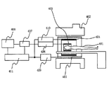
図1は、本発明が適用される典型的なMRI装置の構成を示す図である。このMRI装置は、被検体401が置かれる空間に均一な静磁場を発生する磁石402と、この空間に傾斜磁場を発生する傾斜磁場コイル403と、この空間に高周波(RF)磁場を発生する照射コイル404と、被検体401が発生するNMR信号を検出する受信コイル405を備えている。被検体は、ベッド412に横たわった状態で前記空間に搬入される。
【0012】
傾斜磁場コイル403は、X、Y、Zの3方向の傾斜磁場コイルで構成され、傾斜磁場電源409からの信号に応じてそれぞれ傾斜磁場を発生する。照射コイル404はRF送信部410の信号に応じて高周波磁場を発生する。
【0013】
受信コイル405は、相対的に高感度な小型RFコイルを複数個並べて、各小型RFコイルで受信した信号を合成することにより、小型RFコイルの高い感度を保ったまま視野を拡大し高感度化を図るようにした受信専用RFコイルであり、小型RFコイルとして同種のものを組合せたものや、形状やタイプの異なるものを組合せたものなど公知のマルチプルコイルを採用することができる。また静磁場の向きによって垂直磁場用或いは水平磁場用とする。
【0014】
マルチプルコイルの各小型RFコイルが受信した信号は、信号検出部406で検出され、信号処理部(画像再構成部)407で信号処理され、合成された画像信号に変換される。
【0015】
4つの小型RFコイル602からなるマルチプルコイル601の信号検出部406および信号処理部407の詳細を図2に示す。各小型RFコイル602はそれぞれプリアンプ603を介して、コイル毎にA/D変換器および直交検波回路604を備えた信号検出部406に接続されている。各小型RFコイルで検出された信号は、信号検出部406で二系列のデジタル信号に変換され、信号処理部407に送出される。信号処理部407はこれらデジタル信号に位相補正等の信号処理を行う手段と、画像再構成手段(フーリエ変換手段)605と、画像信号を合成する手段606とを備え、小型RFコイル毎に画像再構成し、これを信号合成する。この信号処理部407は、信号処理手段として後述するナビゲーションエコーを用いた体動補正手段を備えている。合成された画像は表示部408で表示される。
【0016】
制御部11は、これら傾斜磁場電源409、RF送信部410、信号検出部406をパルスシーケンスと呼ばれる撮影シーケンスに従って制御する。本発明ではパルスシーケンスに、画像再構成に必要なNMR信号の取得の際に、ナビゲーションエコーを付加的に発生し、取得する制御が加えられる。
【0017】
ナビゲーションエコーの発生を含むパルスシーケンスの1例を図3に示す。このパルスシーケンスは、スピンエコー法を基本としたシーケンスで、被検体の組織を構成する原子核スピンを励起するRF磁場203と励起した磁化を反転するRF磁場204を、スライスを選択する傾斜磁場205、206と同時に印加した後、信号に位相エンコードを付与する傾斜磁場207を印加し、極性が反転する傾斜磁場208を印加してサンプリング時間209にNMR信号をスピンエコー信号210として計測する。図示するシーケンス211を位相エンコード傾斜磁場の強度を変えながら繰り返し時間202TRで繰り返し、画像再構成に必要な数のエコー信号210を取得する。
【0018】
ナビゲーションエコーを発生し、取得するステップ304は、反転RF磁場204と位相エンコード傾斜磁場207との間に挿入され、このステップ304では極性が判定する読み出し傾斜磁場301を印加してサンプリング時間302にナビゲーションエコー303を計測する。このナビゲーションエコーは位相エンコードが付与されていない位相エンコード量0の信号である。図示する例では繰り返し時間TR毎に1つのナビゲーションエコーを取得しているが、繰り返し時間が短いシーケンスの場合には、いくつかの繰り返し毎に1つのナビゲーションエコーを取得するようにしてもよい、繰り返し時間TR内に例えば複数の軸についてナビゲーションエコーを取得するようにしてもよい。
【0019】
次に本発明のMRI装置において、このようなナビゲーションエコーを用いて画像のために計測したエコー信号210(以下、本計測エコーという)を補正する手順について図4を参照して説明する。
【0020】
パルスシーケンスの繰り返しによって計測された本計測エコーはブロック101内に示すように、各小型RF受信コイル毎に増幅され、A/D変換・直交検波後、信号処理部407に送出される。一方、本計測エコーと同時に計測されたナビゲーションエコーについても、ブロック102に示すように各小型RF受信コイル毎に増幅され、A/D変換・直交検波後、信号処理部407に送出される。信号処理部407は、小型RF受信コイル毎に設けられた補正手段103により、小型RF受信コイル毎に計測された本計測エコーとナビゲーションエコーの組で補正を行う。
【0021】
ナビゲーションエコーによる体動補正では、繰り返し時間TR毎に取得されたナビゲーションエコーの一つ、例えば最初のナビゲーションエコーを基準として、ある繰り返し時間内で計測されたナビゲーションエコーと基準ナビゲーションエコーとの位相のずれに基づき、その繰り返し時間内で計測された本計測エコーを補正する。
【0022】
補正手段103による処理方法としては、ハイブリッド空間での補正、実空間での補正などがあり、その実施例を図5〜図7に示す。各図中、ナビゲーションエコー701と本計測エコー信号702は同一の小型RFコイルで計測された組である。
【0023】
図5に示す実施例では、まず取得したナビゲーションエコー701と本計測エコー信号702を、ナビゲーションエコーを取得した軸方向にそれぞれ1次元フーリエ変換703する。例えば図3に示すパルスシーケンスでは、読み出し方向の傾斜磁場301の反転によってナビゲーションエコーを発生しており、このナビゲーションエコーの取得した軸方向は読み出し方向である。
【0024】
ナビゲーションエコーを1次元フーリエ変換した信号について、基準ナビゲーションエコーを1次元フーリエ変化した信号との位相差を求め、この位相差に基づきハイブリッド空間で本計測エコーのナビゲーション補正704を行う。これはナビゲーションエコーを取得した軸方向についての体動補正となる。次いで最初の1次元フーリエ変換703とは異なる軸で1次元フーリエ変換して補正された画像信号706を得る。
【0025】
図6に示す実施例では、計測したナビゲーションエコー701と基準ナビゲーションエコーとの位相差を求め、この位相差に基づき本計測エコー702をk空間でナビゲーション補正704する。その後、本計測エコー702を2次元フーリエ変換(707)し、補正された画像信号706を得る。
【0026】
図7に示す第三の実施例では、ナビゲーションエコー701を、ナビゲーションエコーを取得した軸方向に1次元フーリエ変換(703)し、同様に1次元フーリエ変換後の基準ナビゲーションとの位置変化から相関関係により位相変化量を計算する。この計算された位相変化量を用いて本計測エコー702についてナビゲーション補正704を行う。その後、本計測エコーの2次元フーリエ変換(707)を行い、補正された画像信号706を得る。
【0027】
これらの実施例のナビゲーション補正704においてナビゲーションエコーの位相差を本計測エコーの位相差に変換するには、例えば複素差分により信号の位相変化を取り除く方法がある。
【0028】
尚、信号処理手段407による補正処理は、上記処理のいずれでもよいが、ナビゲーションエコーのフーリエ変換処理や位置関係から位相相関を求める処理等が不要である点で、またピクセル単位の体動を補正し得る点で図6に示す処理が有利である。
【0029】
このような補正処理103を各小型RFコイルについて行った後、各コイル毎に得られた画像信号706を合成して1枚の画像を再構成する。合成は、単に信号の加算処理を行ってもよいが、「マルチプルコイルによる頭頸部MRIの広視野高感度化」(MEDICAL IMAGING TECHNOLOGY, Vol.15, No.6, November 1997)に記載される技術を適用し、各小型RFコイルからの画像信号にその小型RFコイルの感度分布で重み付けして行うことが好ましい。感度分布の重み付けは次式で表わされる。
【0030】
【数1】

このような処理を行うことにより感度分布の異なる小型コイルを組合せたマルチプルコイルでも高いS/Nの画像を得ることができる
このようにして得られた画像は、撮影中に図8に示すように局所的な被検体の動き1022〜1024があった場合でも、各々のRFコイル6021〜6024でこれら動きを補正した後に信号合成して得たものであるので、動きの影響の無い画像となる。勿論、図10(a)に示すように全体的な動き1021がある場合にもその動きを補正した画像を得ることができる。さらに図10(c)に示すような腹部撮影画像において、被検体の背側と腹側で動きが異なる場合でも画像では動きの影響を無くすことができる。
【0031】
尚、以上の実施例では信号処理部407の処理として、パルスシーケンスの繰り返し毎に計測されたナビゲーションエコーのうちの1つを基準としてナビゲーション補正を行う場合を説明したが、プリスキャンを伴う撮影の場合には、このプリスキャンでナビゲーションエコーを取得し、これを基準としてナビゲーション補正することも可能である。そのような実施例を図9に示す。
【0032】
プリスキャンは、外乱等によって本計測エコーに生じる変化を補正するために本計測に先立って実効されるエコー信号の計測であり、この実施例ではプリスキャン111の際にナビゲーションエコー7011とエコー信号7021をそれぞれ各小型RFコイル602で取得する。次に本計測のパルスシーケンスを実行し、本実施例では、ナビゲーションエコー7012と本計測エコー7022をそれぞれ各小型RFコイル602で取得する。
【0033】
信号処理部は、各小型RFコイル毎に、同一の小型RFコイルで計測されたナビゲーションエコー7011と7012を用いて、本計測エコー7022のナビゲーション補正113を行う。この場合、プリスキャン111で取得したナビゲーションエコー7011を基準として、ナビゲーションエコー7012の位相差を求め、対応する本計測エコー7022を補正する。この補正方法は、図5〜図7に示す実施例のいずれの方法であってもよい。次にナビゲーション補正された信号について、プリスキャン111で取得したエコー信号7011を用いた補正114を行う。この補正114は、例えば位相補正や振幅補正であり、計測空間で行うこともハイブリッド空間で行うことも可能であるが、ナビゲーション補正と合せることが好適である。
【0034】
このように小型RFコイル毎に信号補正114を行った後、補正が計測空間或いはハイブリッド空間の補正であれば必要なフーリエ変換後、補正後の信号706を得る。これを前述のように合成し画像を得る。この場合にも、各小型RFコイルで取得した信号でナビゲーション補正を行った後、信号合成を行うので撮影の対象である組織が局所に動いた場合でも、画像では動きの影響を無くすことができる。
【0035】
本発明は、以上の実施例で開示された内容にとどまらず、各種形態を取り得る。例えば、上記実施例では、パルスシーケンスとしてSEシーケンスを記載したが、FSEシーケンスやEPIシーケンスに本発明を適用してもよい。また本発明におけるナビゲーションエコーを付加的に発生し、取得する機能として、読み出し方向のナビゲーションエコーを適用する場合を示したが、オービタルナビゲーションエコーや、3次元イメージングのスライスエンコード方向、2次元イメージングの位相エンコード方向のナビゲーションエコーを用いて本発明の補正を行うことも可能である。また、2軸以上にナビゲーションエコーを適用してもよい。さらに、計測空間やハイブリッド空間のナビゲーンョン補正を組み合わせて用いても良い。
【0036】
【発明の効果】
本発明は、受信コイルとして複数の小型RFコイルからなるマルチプルコイルを採用すると共に信号処理部に小型RFコイル毎にナビゲーション補正する手段を備えたことにより、被検体の局所的な動きを精度良く補正できる。
【図面の簡単な説明】
【図1】本発明が適用されるMRI装置の全体構成を示す図。
【図2】マルチプルコイルの信号検出部と信号処理部を示す図。
【図3】ナビゲーションエコーの発生が付加されたパルスシーケンスを示す図。
【図4】本発明のMRI装置の信号処理部における処理を示す図。
【図5】信号処理部におけるナビゲーション補正の一実施例を示す図。
【図6】信号処理部におけるナビゲーション補正の他の実施例を示す図。
【図7】信号処理部におけるナビゲーション補正の他の実施例を示す図。
【図8】本発明のMRI装置の効果を説明する図。
【図9】信号処理部におけるナビゲーション補正の他の実施例を示す図。
【図10】ナビゲーション補正における課題を説明する図。
【符号の説明】
402・・・・・・静磁場磁石
403・・・・・・傾斜磁場コイル
404・・・・・・照射コイル
405・・・・・・受信コイル
406・・・・・・信号検出部
407・・・・・・信号処理部(画像再構成手段)
408・・・・・・表示部
602・・・・・・小型RF受信コイル[0001]
BACKGROUND OF THE INVENTION
The present invention relates to a nuclear magnetic resonance imaging apparatus (hereinafter referred to as MRI) that measures nuclear magnetic resonance (hereinafter referred to as NMR) signals from hydrogen, phosphorus, etc. in a subject and visualizes nuclear density distribution and relaxation time distribution. In particular, the present invention relates to an MRI apparatus accompanied by the addition of navigation echoes for body motion correction.
[0002]
[Prior art]
In MRI, when measuring an NMR signal generated from a nuclear spin constituting an object tissue by an NMR phenomenon, a gradient magnetic field is applied to give positional information to the signal. As the gradient magnetic field, a gradient magnetic field in the three-axis directions of the slice encode direction, the phase encode direction, and the frequency encode direction is used, and a signal encoded by the gradient magnetic field is Fourier transformed to reconstruct it as a two-dimensional or three-dimensional image. can do.
[0003]
It is known that a large artifact occurs in an image when the subject moves during such MRI imaging. This is called body movement artifact. The reason why this body motion artifact occurs is that a predetermined phase encoding amount at a predetermined measurement point should be given, but the encoded amount is applied to other measurement points by movement, and the movement of the subject is This occurs because the phase of each acquired echo changes before and after and the Fourier transform is performed in the phase encoding direction (or slice encoding direction) including the changed echo.
[0004]
An imaging method using navigation echo has been proposed as a technique to remove this body motion artifact ("High-speed interleaved echo planar imaging using navigator: High-resolution anatomical and functional image in 4 Tesla" MAGNETIC RESONANCE IN MEDICINE 35: 895-902, June 1996, Seong-Gi Kim et al). In this method, when the imaging sequence is repeated, for example, an echo signal having a phase encoding amount of 0 is generated separately from the original measurement echo (NMR signal) at each repetition, and this is used as a navigation echo. From the change in the phase of the echo, the phase change of the signal due to the body movement generated during the repetition is estimated and corrected.
[0005]
[Problems to be solved by the invention]
However, the imaging method using the navigation echo may not be able to cope with local body movement in the imaging field of view. For example, as shown in FIG. 10A, when a
[0006]
Therefore, the present invention is capable of correcting body motion even in the presence of local body motion in an MRI apparatus having a function of additionally generating and acquiring navigation echoes, and thereby soft as in the abdominal region. An object of the present invention is to provide an MRI apparatus that can accurately capture tissue.
[0007]
[Means for Solving the Problems]
In order to achieve the above object, the MRI apparatus of the present invention includes a means for applying each magnetic field of a high-frequency magnetic field and a gradient magnetic field to a space where a subject is placed according to a predetermined pulse sequence, a receiving coil for receiving an NMR signal, In an MRI apparatus provided with means for processing NMR signals received by a receiving coil and reconstructing an image, a multiple coil comprising a plurality of small RF receiving coils is used as a receiving coil, and the image reconstruction means is small Each RF receiving coil is provided with means for correcting the body movement of the subject, and the signals corrected by the respective correction means are combined to obtain an image with corrected body movement.
[0008]
In the MRI apparatus of the present invention, the image reconstructing means includes body motion correcting means for each small RF receiving coil constituting the multiple coil, and an appropriate body for each set of echo signals acquired by each small RF receiving coil. After correcting the movement, signal synthesis is performed to obtain an image, so that the local movement of the subject can be accurately corrected.
[0009]
As body motion correction, body motion correction using navigation echo can be adopted, and in that case, the body motion correction means detects the additionally generated navigation echo for each small RF receiving coil in the repetition of the pulse sequence. The acquisition means and the means for correcting the body movement of the subject by the combination of the navigation echo and the echo signal acquired by the same small RF receiving coil.
[0010]
DETAILED DESCRIPTION OF THE INVENTION
Embodiments of the MRI apparatus of the present invention will be described below with reference to the drawings.
[0011]
FIG. 1 is a diagram showing a configuration of a typical MRI apparatus to which the present invention is applied. This MRI apparatus includes a
[0012]
The gradient
[0013]
The
[0014]
A signal received by each small RF coil of the multiple coil is detected by a
[0015]
The details of the
[0016]
The control unit 11 controls the gradient magnetic
[0017]
An example of a pulse sequence including the generation of navigation echoes is shown in FIG. This pulse sequence is a sequence based on a spin echo method, an RF
[0018]
The
[0019]
Next, in the MRI apparatus of the present invention, a procedure for correcting an
[0020]
As shown in
[0021]
In body motion correction using navigation echoes, one of the navigation echoes acquired at each repetition time TR, for example, the phase shift between the navigation echo measured within a certain repetition time and the reference navigation echo with reference to the first navigation echo. Based on the above, the main measurement echo measured within the repetition time is corrected.
[0022]
As processing methods by the correcting means 103, there are a correction in a hybrid space, a correction in a real space, and the like, and examples thereof are shown in FIGS. In each figure, the
[0023]
In the embodiment shown in FIG. 5, first, the acquired
[0024]
A phase difference between a signal obtained by one-dimensional Fourier transform of the navigation echo and a signal obtained by changing the reference navigation echo by one-dimensional Fourier is obtained, and
[0025]
In the embodiment shown in FIG. 6, the phase difference between the measured
[0026]
In the third embodiment shown in FIG. 7, the
[0027]
In order to convert the phase difference of the navigation echo into the phase difference of the main measurement echo in the
[0028]
The correction processing by the signal processing means 407 may be any of the above processings, but correction of body movement in units of pixels is also necessary in that the Fourier transform processing of navigation echo and the processing for obtaining the phase correlation from the positional relationship are unnecessary. In view of this possibility, the process shown in FIG. 6 is advantageous.
[0029]
After
[0030]
[Expression 1]
By performing such processing, a high S / N image can be obtained even with a multiple coil combined with small coils having different sensitivity distributions. An image obtained in this way is shown in FIG. Even if there are
[0031]
In the above embodiment, the processing of the
[0032]
Prescan is measurement of an echo signal that is executed prior to the main measurement in order to correct a change that occurs in the main measurement echo due to disturbance or the like. In this embodiment, the
[0033]
The signal processing unit performs
[0034]
After performing the
[0035]
The present invention is not limited to the contents disclosed in the above embodiments, and can take various forms. For example, in the above embodiment, the SE sequence is described as the pulse sequence, but the present invention may be applied to an FSE sequence or an EPI sequence. Further, the case where the navigation echo in the readout direction is applied as a function for additionally generating and acquiring the navigation echo in the present invention has been shown, but the orbital navigation echo, the slice encoding direction of the three-dimensional imaging, and the phase of the two-dimensional imaging. It is also possible to perform the correction of the present invention using navigation echoes in the encoding direction. Navigation echoes may be applied to two or more axes. Furthermore, navigation correction in a measurement space or a hybrid space may be used in combination.
[0036]
【The invention's effect】
The present invention employs a multiple coil composed of a plurality of small RF coils as a receiving coil, and includes a means for correcting navigation for each small RF coil in the signal processing unit, thereby accurately correcting the local movement of the subject. it can.
[Brief description of the drawings]
FIG. 1 is a diagram showing an overall configuration of an MRI apparatus to which the present invention is applied.
FIG. 2 is a diagram illustrating a signal detection unit and a signal processing unit of a multiple coil.
FIG. 3 is a diagram showing a pulse sequence to which generation of navigation echo is added.
FIG. 4 is a diagram showing processing in a signal processing unit of the MRI apparatus of the present invention.
FIG. 5 is a diagram illustrating an example of navigation correction in a signal processing unit.
FIG. 6 is a diagram showing another embodiment of navigation correction in the signal processing unit.
FIG. 7 is a diagram showing another embodiment of navigation correction in the signal processing unit.
FIG. 8 is a diagram for explaining the effect of the MRI apparatus of the present invention.
FIG. 9 is a diagram showing another embodiment of navigation correction in the signal processing unit.
FIG. 10 is a diagram illustrating a problem in navigation correction.
[Explanation of symbols]
402 ・ ・ ・ ・ ・ ・ Static field magnet
403 ・ ・ ・ ・ ・ ・ Gradient magnetic field coil
404 ・ ・ ・ ・ ・ ・ Irradiation coil
405 ... Receiving coil
406 ... Signal detector
407 ・ ・ ・ ・ ・ ・ Signal processing unit (image reconstruction means)
408 ... Display section
602 ・ ・ ・ ・ ・ ・ Small RF receiver coil
Claims (2)
前記受信コイルとして、複数の小型RF受信コイルからなるマルチプルコイルを用いるとともに、前記画像再構成手段は、前記小型RF受信コイル毎に、その受信信号から前記被検体の対応部位の体動量を示す信号をそれぞれ求め、これを用いて前記小型 RF 受信コイル毎に、前記核磁気共鳴信号またはこれを再構成した画像信号を補正する体動補正手段を備え、該体動補正手段によって補正された前記核磁気共鳴信号または画像信号を合成し体動の補正された画像を得ることを特徴とする核磁気共鳴撮像装置。Means for applying a high-frequency magnetic field and a gradient magnetic field to the space in which the subject is placed according to a predetermined pulse sequence, a receiving coil for receiving a nuclear magnetic resonance signal, and processing the nuclear magnetic resonance signal received by the receiving coil And a nuclear magnetic resonance imaging apparatus comprising means for reconstructing an image,
As the receiving coil, with using multiple coil composed of a plurality of small RF receiver coil, wherein the image reconstruction means, for each of the small RF receiver coils, a signal indicating the body movement of the corresponding region of the subject from the received signal seek respectively, for each of the small RF receiver coil with this, with the body motion correcting means for correcting said magnetic resonance signals or image signals reconstructed this, the nuclei corrected by said body motion correcting means A nuclear magnetic resonance imaging apparatus characterized in that a magnetic resonance signal or an image signal is synthesized to obtain an image in which body motion is corrected.
前記体動補正手段は、前記パルスシーケンスの繰り返しにおいて、付加的に発生したナビゲーションエコーを前記小型RF受信コイル毎に取得する手段と、同一の前記小型RF受信コイルで取得された前記ナビゲーションエコーと前記核磁気共鳴信号の組で前記被検体の体動を補正する手段とからなることを特徴とする核磁気共鳴撮像装置。The nuclear magnetic resonance imaging apparatus according to claim 1,
The body movement correcting means, said in the repetition of the pulse sequence and means for acquiring additionally navigator echo generated in each of the small RF receiver coils, and the navigator echo obtained in the same the small RF receiver coil nuclear magnetic resonance imaging apparatus characterized by comprising a means for correcting the motion of the subject with a set of nuclear magnetic resonance signals.
Priority Applications (1)
| Application Number | Priority Date | Filing Date | Title |
|---|---|---|---|
| JP33586398A JP4072879B2 (en) | 1998-11-26 | 1998-11-26 | Nuclear magnetic resonance imaging system |
Applications Claiming Priority (1)
| Application Number | Priority Date | Filing Date | Title |
|---|---|---|---|
| JP33586398A JP4072879B2 (en) | 1998-11-26 | 1998-11-26 | Nuclear magnetic resonance imaging system |
Publications (3)
| Publication Number | Publication Date |
|---|---|
| JP2000157507A JP2000157507A (en) | 2000-06-13 |
| JP2000157507A5 JP2000157507A5 (en) | 2006-01-19 |
| JP4072879B2 true JP4072879B2 (en) | 2008-04-09 |
Family
ID=18293233
Family Applications (1)
| Application Number | Title | Priority Date | Filing Date |
|---|---|---|---|
| JP33586398A Expired - Fee Related JP4072879B2 (en) | 1998-11-26 | 1998-11-26 | Nuclear magnetic resonance imaging system |
Country Status (1)
| Country | Link |
|---|---|
| JP (1) | JP4072879B2 (en) |
Families Citing this family (15)
| Publication number | Priority date | Publication date | Assignee | Title |
|---|---|---|---|---|
| JP4443079B2 (en) | 2001-09-13 | 2010-03-31 | 株式会社日立メディコ | Magnetic resonance imaging apparatus and RF receiving coil for magnetic resonance imaging apparatus |
| JP4283115B2 (en) * | 2001-12-14 | 2009-06-24 | コーニンクレッカ フィリップス エレクトロニクス エヌ ヴィ | Diffusion-weighted parallel imaging method with phase correction based on navigator signal |
| WO2006051911A1 (en) * | 2004-11-12 | 2006-05-18 | Kabushiki Kaisha Toshiba | Magnetic resonance imaging apparatus, image data correction apparatus, and image data correction method |
| JP4721857B2 (en) * | 2005-01-12 | 2011-07-13 | 株式会社日立メディコ | Magnetic resonance imaging apparatus and image reconstruction method using the same |
| WO2006117723A1 (en) * | 2005-05-02 | 2006-11-09 | Koninklijke Philips Electronics N.V. | Independent motion correction in respective signal channels of a magnetic resonance imaging system |
| JP4781120B2 (en) * | 2006-02-03 | 2011-09-28 | 株式会社日立メディコ | Magnetic resonance imaging apparatus and magnetic resonance spectrum measuring method |
| JP5105848B2 (en) * | 2006-02-06 | 2012-12-26 | 株式会社東芝 | Magnetic resonance imaging apparatus and imaging condition setting method in magnetic resonance imaging apparatus |
| CN100570393C (en) * | 2006-02-06 | 2009-12-16 | 株式会社东芝 | MR imaging apparatus and MR imaging method |
| WO2008010126A1 (en) * | 2006-07-18 | 2008-01-24 | Koninklijke Philips Electronics N.V. | Artifact suppression in multi-coil mri |
| JP4896763B2 (en) | 2007-02-19 | 2012-03-14 | 株式会社東芝 | Respiratory suppression member and magnetic resonance imaging apparatus |
| US8971992B2 (en) | 2007-05-07 | 2015-03-03 | Kabushiki Kaisha Toshiba | Magnetic resonance imaging apparatus and control method thereof |
| US8818487B2 (en) | 2008-10-15 | 2014-08-26 | Kabushiki Kaisha Toshiba | Magnetic resonance imaging apparatus and magnetic resonance imaging method |
| JP5591545B2 (en) | 2010-01-20 | 2014-09-17 | 株式会社東芝 | Magnetic resonance imaging system |
| US10067213B2 (en) * | 2010-12-22 | 2018-09-04 | Koninklijke Philips N.V. | Parallel MRI method using calibration scan, coil sensitivity maps and navigators for rigid motion compensation |
| JP6867876B2 (en) * | 2017-05-25 | 2021-05-12 | 株式会社日立製作所 | Magnetic resonance imaging device and body motion correction method |
-
1998
- 1998-11-26 JP JP33586398A patent/JP4072879B2/en not_active Expired - Fee Related
Also Published As
| Publication number | Publication date |
|---|---|
| JP2000157507A (en) | 2000-06-13 |
Similar Documents
| Publication | Publication Date | Title |
|---|---|---|
| JP6513398B2 (en) | MR image reconstruction using prior information constrained regularization | |
| JP3952247B2 (en) | Nuclear magnetic resonance imaging system | |
| JP3815585B2 (en) | Magnetic resonance imaging system | |
| JP4152381B2 (en) | Magnetic resonance imaging system | |
| JP6243522B2 (en) | Parallel MRI with multi-echo Dixon water-fat separation and B0 distortion correction using regularized detection reconstruction | |
| US7319324B2 (en) | MRI method and apparatus using PPA image reconstruction | |
| JP5599893B2 (en) | MR imaging using navigator | |
| US7372269B2 (en) | Magnetic resonance imaging method and apparatus | |
| EP2626718A1 (en) | MRI with motion correction using navigators acquired using a Dixon technique | |
| JP4072879B2 (en) | Nuclear magnetic resonance imaging system | |
| JP2003079595A (en) | Magnetic resonance imaging device and rf receiving coil therefor | |
| JP2006507071A (en) | Magnetic resonance method | |
| JP4202855B2 (en) | Magnetic resonance imaging system | |
| US20060164087A1 (en) | Magnetic resonance method and device | |
| JP4343317B2 (en) | Magnetic resonance imaging system | |
| JP2952228B1 (en) | Continuous MRI image reconstruction method and apparatus | |
| CN112912749A (en) | MR imaging using motion compensated image reconstruction | |
| JP4675936B2 (en) | Nuclear magnetic resonance imaging system | |
| JP3983792B2 (en) | Nuclear magnetic resonance imaging system | |
| EP2392935A1 (en) | EPI distortion correction using non-phase encoded reference echoes | |
| JP4912156B2 (en) | Magnetic resonance imaging method and apparatus | |
| JP3952310B2 (en) | Nuclear magnetic resonance imaging system | |
| JP3615302B2 (en) | Magnetic resonance imaging system | |
| CN111164444A (en) | Dixon-type water/fat separation MR imaging with improved fat displacement correction | |
| EP4012434A1 (en) | Dixon-type water/fat separation mr imaging |
Legal Events
| Date | Code | Title | Description |
|---|---|---|---|
| A521 | Written amendment |
Free format text: JAPANESE INTERMEDIATE CODE: A523 Effective date: 20051122 |
|
| A621 | Written request for application examination |
Free format text: JAPANESE INTERMEDIATE CODE: A621 Effective date: 20051122 |
|
| A977 | Report on retrieval |
Free format text: JAPANESE INTERMEDIATE CODE: A971007 Effective date: 20071030 |
|
| A131 | Notification of reasons for refusal |
Free format text: JAPANESE INTERMEDIATE CODE: A131 Effective date: 20071106 |
|
| A521 | Written amendment |
Free format text: JAPANESE INTERMEDIATE CODE: A523 Effective date: 20071218 |
|
| TRDD | Decision of grant or rejection written | ||
| A01 | Written decision to grant a patent or to grant a registration (utility model) |
Free format text: JAPANESE INTERMEDIATE CODE: A01 Effective date: 20080116 |
|
| A61 | First payment of annual fees (during grant procedure) |
Free format text: JAPANESE INTERMEDIATE CODE: A61 Effective date: 20080117 |
|
| FPAY | Renewal fee payment (event date is renewal date of database) |
Free format text: PAYMENT UNTIL: 20110201 Year of fee payment: 3 |
|
| R150 | Certificate of patent or registration of utility model |
Free format text: JAPANESE INTERMEDIATE CODE: R150 |
|
| FPAY | Renewal fee payment (event date is renewal date of database) |
Free format text: PAYMENT UNTIL: 20120201 Year of fee payment: 4 |
|
| FPAY | Renewal fee payment (event date is renewal date of database) |
Free format text: PAYMENT UNTIL: 20130201 Year of fee payment: 5 |
|
| FPAY | Renewal fee payment (event date is renewal date of database) |
Free format text: PAYMENT UNTIL: 20140201 Year of fee payment: 6 |
|
| LAPS | Cancellation because of no payment of annual fees |