JP4202855B2 - Magnetic resonance imaging system - Google Patents
Magnetic resonance imaging system Download PDFInfo
- Publication number
- JP4202855B2 JP4202855B2 JP2003279564A JP2003279564A JP4202855B2 JP 4202855 B2 JP4202855 B2 JP 4202855B2 JP 2003279564 A JP2003279564 A JP 2003279564A JP 2003279564 A JP2003279564 A JP 2003279564A JP 4202855 B2 JP4202855 B2 JP 4202855B2
- Authority
- JP
- Japan
- Prior art keywords
- data
- image
- magnetic resonance
- measurement
- sensitivity
- Prior art date
- Legal status (The legal status is an assumption and is not a legal conclusion. Google has not performed a legal analysis and makes no representation as to the accuracy of the status listed.)
- Expired - Lifetime
Links
Images


Description
本発明は核磁気共鳴現象を用いて被検体の断層像を得る磁気共鳴イメージング(以下、「MRI」という)装置に関し、特に、パラレルイメージングにおいてトータルの撮像時間を短縮する技術に関する。 The present invention relates to a magnetic resonance imaging (hereinafter referred to as “MRI”) apparatus that obtains a tomographic image of a subject using a nuclear magnetic resonance phenomenon, and more particularly to a technique for shortening the total imaging time in parallel imaging.
MRI装置における高速撮像法として、パラレルイメージング法が公知([非特許文献3])である。これは、複数の受信コイルから成るマルチプル受信コイルを用いて位相エンコードステップを等間隔に間引いて計測を行い、各受信コイルの感度分布を用いて画像を展開することにより折り返しのない画像を得る技術である。MRIの撮影では、位相エンコードステップの数と撮影時間は比例関係にあるため、パラレルイメージングでは計測する位相エンコード数を減らすことにより撮影時間を短縮することができる。 As a high-speed imaging method in an MRI apparatus, a parallel imaging method is known ([Non-Patent Document 3]). This is a technique that uses multiple receiving coils consisting of multiple receiving coils to measure by thinning out phase encoding steps at equal intervals, and develops an image using the sensitivity distribution of each receiving coil to obtain an unfolded image. It is. In MRI imaging, the number of phase encoding steps and the imaging time are in a proportional relationship. Therefore, in parallel imaging, the imaging time can be shortened by reducing the number of phase encodings to be measured.
パラレルイメージングにおけるk空間充填の方法として、図2に示す2つの方法が知られている。1つは、プリスキャンで感度データ201を収集し、本計測では設定したファクターに応じて位相エンコードステップを間引いたデータ(以下、「折り返しデータ」という)202のみを収集するプリスキャンキャリブレーション法([特許文献1])、もう1つは、本計測で感度データと折り返しデータを一度に収集(203)した後、感度データ204と折り返しデータ205に分割するセルフキャリブレーション法([特許文献2])である。プリスキャンキャリブレーション法は、本計測では設定したファクターに応じて位相エンコードステップを間引くので、撮影時間がちょうど1/(設定ファクター)となる。どちらの方法も感度データを収集するタイミングが異なるものの、位相エンコードステップを設定ファクターに応じて間引く点は共通である。
Two methods shown in FIG. 2 are known as a k-space filling method in parallel imaging. One is a pre-scan calibration method that collects
以上がパラレルイメージングの撮影方法であり、上記どちらの方法においてもパラレルイメージングを行う場合は、感度データと折り返しデータの収集を撮影の度に毎回行う。
しかし、プリスキャンキャリブレーション法では、プリスキャンで感度データを収集するためプリスキャン時間が延長し、また動きが大きいと画像がボケる場合がある。一方、セルフキャリブレーション法では、プリスキャン時間が延長することなく、被検体の動きに強いという特徴があるが、低周波成分領域のデータを密に収集するためプリスキャンキャリブレーション法に比べて本計測の撮像時間が長くなる。 However, in the pre-scan calibration method, sensitivity data is collected by pre-scan, so that the pre-scan time is extended, and if the movement is large, the image may be blurred. On the other hand, the self-calibration method is characterized by being resistant to the movement of the subject without extending the pre-scan time. However, since the data of the low-frequency component region is collected densely, the self-calibration method is more effective than the pre-scan calibration method. The imaging time for measurement becomes longer.
どちらの方法においてもパラレルイメージングを行う場合は、感度データと折り返しデータの収集を撮影の度に毎回行うため、撮影時間は単純に1/(設定ファクター)には短縮せず、感度データを収集する分の時間を余計に要している。 When performing parallel imaging with either method, the sensitivity data and aliasing data are collected each time each image is taken, so the shooting time is not simply reduced to 1 / (setting factor), and sensitivity data is collected. It takes an extra minute.
従って、いずれの方法においても、パラレルイメージングにおいて折り返しのない画像を得るためには感度データを収集することが必要であるため、トータルの撮影時間が延長することになり、パラレルイメージングの特徴である短時間撮影の効果を低減させる。この問題は[非特許文献1]には考慮されていない。 Therefore, in any method, since it is necessary to collect sensitivity data in order to obtain an unfolded image in parallel imaging, the total imaging time is extended, which is a characteristic feature of parallel imaging. Reduce the effect of time shooting. This problem is not considered in [Non-Patent Document 1].
そこで、本発明の目的は、パラレルイメージングにおいて、トータルの撮影時間をさらに短縮して折り返しのない良好な画像を取得することである。 Accordingly, an object of the present invention is to further reduce the total imaging time and obtain a good image without aliasing in parallel imaging.
前記課題を解決するために、本発明のMRI装置は次の様に構成される。即ち、
被検体に静磁場を与える静磁場発生手段と、スライス方向と位相エンコード方向と周波数エンコード方向の傾斜磁場を与える傾斜磁場発生手段と、前記被検体内の原子核スピンに核磁気共鳴を誘起する高周波磁場パルスを照射する高周波磁場送信手段と、
核磁気共鳴により前記被検体から放出されるエコー信号を検出する複数のRF受信コイルからなるマルチプルRF受信コイルを備えて、前記RF受信コイル毎の感度データと、計測空間の位相エンコードステップが間引かれた画像用データとを計測するエコー信号受信手段と、
前記RF受信コイル毎の前記画像用データと前記感度データとを用いて、パラレルイメージングに基づく演算により画像を取得する信号処理手段と、
前記エコー信号を受信するパルスシーケンスを制御するパルスシーケンス制御手段と、
を備え、
前記感度データと前記画像用データのどちらか一方又は両方のデータを再計測するか否かを選択する再計測データ選択手段を備え、該再計測データ選択手段によって選択されたデータを再計測する。
In order to solve the above problems, the MRI apparatus of the present invention is configured as follows. That is,
A static magnetic field generating means for applying a static magnetic field to a subject; a gradient magnetic field generating means for applying a gradient magnetic field in a slice direction, a phase encoding direction, and a frequency encoding direction; and a high frequency magnetic field for inducing nuclear magnetic resonance in a nuclear spin in the subject A high-frequency magnetic field transmitting means for irradiating a pulse;
Provided with multiple RF receiving coils comprising a plurality of RF receiving coils for detecting echo signals emitted from the subject by nuclear magnetic resonance, the sensitivity data for each RF receiving coil and the phase encoding step of the measurement space are thinned out. Echo signal receiving means for measuring the image data,
Using the image data and the sensitivity data for each RF receiving coil, signal processing means for acquiring an image by calculation based on parallel imaging ;
Pulse sequence control means for controlling a pulse sequence for receiving the echo signal;
With
Re-measurement data selection means for selecting whether or not to re-measure one or both of the sensitivity data and the image data is provided, and the data selected by the re-measurement data selection means is re-measured.
これにより、パラレルイメージングにおいて、再計測する必要のないデータを計測しなくて済むので、トータルの撮影時間をさらに短縮して折り返しのない良好な画像を取得することができる。 Thereby, in parallel imaging, it is not necessary to measure data that does not need to be remeasured, so that the total photographing time can be further shortened and a good image without aliasing can be acquired.
また、好ましい一実施態様によれば、本発明のMRI装置において、前記再計測データ選択手段が前記感度データのみの再計測を選択して、前記感度データのみが再計測された場合に、前記信号処理手段は、計測済みの前記画像用データと該再計測された感度データとから前記パラレルイメージングに基づく演算により画像を取得する。
According to a preferred embodiment, in the MRI apparatus of the present invention, when the remeasurement data selection unit selects remeasurement of only the sensitivity data, and only the sensitivity data is remeasured, the signal The processing means acquires an image from the measured image data and the remeasured sensitivity data by a calculation based on the parallel imaging .
これにより、パラレルイメージングにおいて、感度データのみ再計測して時間のかかる画像用データを再計測しないので、画像用データの計測時間を短縮でき、トータルの撮影時間をさらに短縮することができる。
特に、腹部息止め撮像において、感度データ計測時と画像用データ計測時とで息止めレベルが異なる場合には、計測時間の短い感度データを再計測することによるトータルの撮影時間の短縮は患者に対する効果が大きい。
Accordingly, in parallel imaging, only the sensitivity data is remeasured and time-consuming image data is not remeasured, so that the image data measurement time can be reduced, and the total imaging time can be further reduced.
In particular, in abdominal breath-hold imaging, if the breath-hold level differs between sensitivity data measurement and image data measurement, the total imaging time reduction by re-measurement of sensitivity data with a short measurement time is Great effect.
また、好ましい一実施態様によれば、本発明のMRI装置において、前記再計測データ選択手段が前記画像用データのみの再計測を選択して、前記画像用データのみが再計測された場合に、前記信号処理手段は、計測済みの前記感度データと該再計測された画像用データとから前記パラレルイメージングに基づく演算により画像を取得する。
According to a preferred embodiment, in the MRI apparatus of the present invention, when the remeasurement data selection unit selects remeasurement of only the image data, and only the image data is remeasured, The signal processing unit obtains an image from the measured sensitivity data and the remeasured image data by an operation based on the parallel imaging .
これにより、パラレルイメージングにおいて、画像用データのみ再計測して感度データを再計測しないので、感度データの計測時間を短縮でき、トータルの撮影時間をさらに短縮することができる。特に、時間のかかる画像用データ計測時に被検体が動いてしまった場合、動いた後以降の画像用データを再計測することにより、トータルの撮影時間の短縮効果が大きくなる。 Thereby, in parallel imaging, only the image data is remeasured and the sensitivity data is not remeasured, so the sensitivity data measurement time can be shortened and the total imaging time can be further shortened. In particular, if the subject moves during time-consuming image data measurement, the effect of shortening the total imaging time is increased by re-measurement of the image data after the movement.
また、好ましい一実施態様によれば、本発明のMRI装置において、前記再計測データ選択手段は、計測済みの前記感度データを計測した場合と同じスライス位置かつ同じFOVの場合には、前記画像用データのみ再計測することを選択する。
Moreover, according to a preferred embodiment, the MRI apparatus of the present invention, the re-measurement data selection means, in the case of instrumented of the sensitivity data Ji same slice position and the same as when the measured FOV, the image choose to re-measurement only use data.
これにより、パラレルイメージングにおいて、同一スライス位置かつ同一FOVの時には、感度データを再計測しなくて済むので、トータルの撮影時間をさらに短縮して折り返しのない良好な画像を取得することができる。 Thus, in parallel imaging, when the same slice position and the same FOV are used, it is not necessary to remeasure sensitivity data, so that the total photographing time can be further reduced and a good image without aliasing can be acquired.
また、好ましい一実施態様によれば、本発明のMRI装置において、前記被検体の同一断面の撮影を複数回連続して繰り返す場合において、2回目以降の撮影では1回目の撮影で計測した感度データを用いる。 According to a preferred embodiment, in the MRI apparatus of the present invention, when the imaging of the same cross section of the subject is continuously repeated a plurality of times, the sensitivity data measured in the first imaging in the second and subsequent imaging. Is used.
これにより、特に、ダイナミックスキャンやフルオロスコピー計測において、2回目以降の撮影を高速に行うことが可能となる。あるいは、同じスライス位置をT1強調像、T2強調像、FLAIR像と撮影する場合に、T1強調像の取得時に感度データを収集すれば、以降のT2強調像、FLAIR像の取得時には感度データの計測を省略でき、撮影全体の時間が更に短縮できる。 This makes it possible to perform the second and subsequent shooting at high speed, particularly in dynamic scanning and fluoroscopy measurement. Alternatively, if the same slice position is taken as a T1-weighted image, a T2-weighted image, and a FLAIR image, if sensitivity data is collected at the time of acquiring the T1-weighted image, the sensitivity data is measured when the subsequent T2-weighted image and FLAIR image are acquired. Can be omitted, and the time for the entire photographing can be further shortened.
本発明によれば、MRI装置における撮影時間を短縮する技術であるパラレルイメージングにおいて、合成画像の取得に必要な感度データと折り返しデータの計測に関して、次回以降の合成画像の取得の際にいずれか一方を再計測する必要の無い場合には、再計測せずに計測済みのデータを流用することができ、これにより、トータルの撮影時間をさらに短縮して折り返しのない良好な画像を取得することができる。 According to the present invention, in parallel imaging, which is a technique for shortening imaging time in an MRI apparatus, either sensitivity data or aliasing data measurement necessary for acquisition of a composite image is performed at the time of acquisition of a composite image from the next time onward. When it is not necessary to re-measure the image, the measured data can be used without re-measurement, which can further reduce the total shooting time and obtain a good image without aliasing. it can.
特に、被検体の体動があった場合に、再計測が必要な方のデータのみ再計測したり、ダイナミックスキャンやフルオロスコピー計測などの被検体の同一断面の撮影を複数回連続して繰り返す場合に、2回目以降の撮影において感度データの再計測を省略できるので、トータルの撮影時間をさらに短縮でき、被検体の負担を低減することができる。 In particular, when there is body movement of the subject, only re-measurement of the data that requires re-measurement, or when the same cross-section of the subject, such as dynamic scan or fluoroscopy measurement, is repeated multiple times in succession In addition, since the re-measurement of sensitivity data can be omitted in the second and subsequent imaging, the total imaging time can be further shortened and the burden on the subject can be reduced.
以下、本発明を適用したMRI装置の実施形態を、図面に基づいて詳細に説明する。
図7は、本発明に係るMRI装置の概略の全体構成を示すブロック図である。このMRI装置は、核磁気共鳴現象を利用して被験体の断層像を得るためのもので、静磁場発生系701、傾斜磁場発生系702、送信系703、受信系704、信号処理系705、シーケンサ706、中央処理装置707および図示してない操作部とからなる。
Hereinafter, embodiments of an MRI apparatus to which the present invention is applied will be described in detail with reference to the drawings.
FIG. 7 is a block diagram showing a schematic overall configuration of the MRI apparatus according to the present invention. This MRI apparatus is for obtaining a tomographic image of a subject using a nuclear magnetic resonance phenomenon, a static magnetic
静磁場発生系701は、被検体708の周りのある広がりを持った計測空間に配置された永久磁石、常伝導磁石、または、超電導磁石のいずれかからなり、被検体708の周囲にその体軸方向または被検体の体軸と直交する方向に均一な静磁場を発生させる。
The static magnetic
傾斜磁場発生系702は、X,Y,Zの3軸方向に巻かれた傾斜磁場コイル709と、これら各コイルに電流を供給する傾斜磁場電源710とからなり、シーケンサ706からの命令に従って傾斜磁場電源710の各々のコイルに電流を流すことによりX,Y,Zの3軸方向の傾斜磁場Gs,Gp,Gfを被検体708に印加する。この傾斜磁場の加え方により、被検体708を撮影して表示する断面が設定される。
The gradient magnetic
送信系703は、高周波発振器711、変調器712、高周波増幅器713および高周波照射コイル714とからなり、傾斜磁場発生系702で設定された被検体708の撮影断面の生体組織を構成する原子の原子核を励起して核磁気共鳴を起こさせるために、高周波発振器711から出力された高周波パルスを変調機712で振幅変調し、高周波増幅器713で増幅した後に、被検体708に近接して設置された高周波照射コイル714に供給して被検体に照射する。
The
受信系704は、高周波受信コイル715、受信回路716およびアナログ/ディジタル(以下「A/D」という)変換器717とからなり、送信系703の高周波照射コイル714から照射された電磁波による被検体708の生体組織の原子核の核磁気共鳴によるエコー信号であるNMR信号を、被検体708に近接して配置された高周波受信コイル715で検出し、受信回路716を介してA/D変換器717に入力し、ディジタル信号に変換して、さらにシーケンサ706からの命令によるタイミングでサンプリングされた収集データとして、その信号データを信号処理系5に送る。
The
信号処理系705は、収集データに対しフーリエ変換およびシーケンサ706の制御を行うCPU707、本発明の補正手段を含み補正計算や収集データを断層像に再構成するために必要な処理を行う信号処理装置718、経時的な画像解析処理および指定された計測のシーケンスのプログラムやその実行の際に用いられるパラメータ等を記憶し、被検体に対して行った事前の計測で得た計測パラメータや受信系704で検出したNMR信号からの収集データおよび関心領域設定に用いる画像を一時保管すると共にその関心領域を設定するためのパラメータ等を記憶するメモリ719、再構成された画像データを記憶するデータ格納部となる磁気ディスク720・光ディスク721およびこれらのディスクから読み出した画像データを映像化して断層像として表示するディスプレイ722とからなり、受信系704で検出したNMR信号を用いて画像再構成演算を行うとともに画像表示を行う。
The
シーケンサ706は、CPU707の制御で動作しスライスエンコード、位相エンコード、周波数エンコードの各傾斜磁場および高周波磁場パルスをある所定のパルスシーケンスで繰り返し発生するためのもので、被検体708の断層像のデータ取得に必要な種々の命令を傾斜磁場発生系702、送信系703および受信系704に送る。
操作部(図示してない)は、トラックボールまたはマウス、キーボード等からなり信号処理系705で行う処理の制御情報を入力する。
The
An operation unit (not shown) includes a trackball, a mouse, a keyboard, or the like, and inputs control information for processing performed by the
次に、上記構成のMRI装置を用いた撮影方法について説明する。
図3は一般的なグラディエントエコーシーケンスである。スライス選択傾斜磁場パルス302と共に高周波(RF)パルス301を印加し、被検体の特定の領域の核スピンを励起して横磁化を発生させた後、位相エンコード傾斜磁場パルス303を印加し、次いで読み出し傾斜磁場パルス304を印加し、エコー信号305を計測する。高周波(RF)パルス301からエコー信号305までの時間(エコー時間)TEは画像コントラストを決めるパラメータの1つであり、対象とする組織等を考慮して予め設定される。
Next, an imaging method using the MRI apparatus having the above configuration will be described.
FIG. 3 shows a general gradient echo sequence. A radio frequency (RF) pulse 301 is applied together with the slice selective gradient
このようなシーケンスを位相エンコード傾斜磁場303の面積(印加時間について磁場強度を積分した値)を変えながら、例えば複数回繰り返し、k空間上のデータを計測する。パラレルイメージングでは、複数の受信コイルからなるマルチプル受信コイルを用いて、設定したファクターに応じて位相エンコードステップを間引いて計測する。この計測データは、受信コイル(715)毎に信号処理系(705)に送られ、ここで図4に示すように各受信コイルの感度分布の計算402と、各受信コイルからの信号の合成処理404が行われる。即ち、各コイルからの信号en(kx,ky)401を用いて各コイルの感度分布画像Wn(x,y)403を求める。図4で、nはコイル番号で、この実施例ではn=1,2,3または4である。また、(kx,ky)はk空間の座標を、(x,y)は実空間上の位置を表す。感度分布と受信信号を使って、全体画像S(x,y)405を合成する。これら感度分布計算402と合成処理404について更に詳述する。
Such a sequence is repeated, for example, a plurality of times while changing the area of the phase encoding gradient magnetic field 303 (the value obtained by integrating the magnetic field intensity with respect to the application time), and data in the k space is measured. In parallel imaging, measurement is performed by thinning out the phase encoding step according to a set factor using a multiple receiving coil including a plurality of receiving coils. This measurement data is sent to the signal processing system (705) for each receiving coil (715). Here, as shown in FIG. 4, the
最初に、各受信コイルにおいて信号en(kx,ky)401からRFコイルの感度分布を計算する手順を説明する。まず感度データ(k空間上のデータ)において、位相エンコード方向に低周波通過フィルタ(LPF)を作用させる。これにより、高周波領域のデータは全てゼロとなり、信号を収集した部分とゼロデータの境界部分は滑らかにゼロにつながるようにする。次に、k空間の全体を2次元フーリエ変換(2DFT)し、低周波成分のみを画像化する。この画像は、RFコイルの感度分布(実空間上のデータ)と見なせることが知られており、本実施形態でもこれを感度分布Wn(x,y)とする。 First, a procedure for calculating the sensitivity distribution of RF coil from signal e n (kx, ky) 401 in each receiving coil. First, a low-frequency pass filter (LPF) is applied in the phase encoding direction for sensitivity data (data in k space). As a result, all the data in the high frequency region becomes zero, and the boundary where the signal is collected and the boundary between the zero data are smoothly connected to zero. Next, the entire k-space is subjected to two-dimensional Fourier transform (2DFT), and only the low frequency component is imaged. It is known that this image can be regarded as a sensitivity distribution (data in real space) of the RF coil, and this is also referred to as a sensitivity distribution W n (x, y) in this embodiment.
次に、この感度分布Wn(x,y)を用いて折り返しを除去する合成演算404について説明する。合成演算は、画像空間(実空間)で行う方法と、計測空間(k空間)で行う方法とがある。
Next, a
図5に、画像空間で行う方法を説明する。ここでは説明を簡単にするためにFOVの左右に2つのコイルを配置した例を示す。A点の信号は、位相エンコードステップを間引いたことによる折り返しによりB点と重なっている。B点の信号を本来のA点の信号S(x+Δx, y)とB点の信号S(x, y)に分解することにより、折り返しのない画像を得る。ここで、Δxは折り返しの距離を意味する。 FIG. 5 illustrates a method performed in the image space. Here, in order to simplify the explanation, an example in which two coils are arranged on the left and right sides of the FOV is shown. The signal at point A overlaps with point B due to the aliasing caused by thinning out the phase encoding step. By decomposing the B point signal into the original A point signal S (x + Δx, y) and the B point signal S (x, y), an unfolded image is obtained. Here, Δx means a folding distance.
FOV左側に配置したcoil1(501)が生成する画像504から得る感度係数をW1(x+Δx, y), W1(x, y)、FOV右側に配置したcoil2(502)が生成する画像505から得る感度係数をW2(x+Δx, y), W2(x, y)とする。これらから、以下の式が成立する。
コイル1のB点の実測信号強度S1(x, y)
= W1(x+Δx, y)・S(x+Δx, y) + W1(x, y)・S(x, y)
コイル2のB点の実測信号強度S2(x, y)
= W2(x+Δx, y)・S(x+Δx, y) + W2(x, y)・S(x, y)
それぞれのコイルのB点の実測信号強度を測定し、連立方程式によりS(x+Δx, y), S(x, y)を算出する。このように、コイルそれぞれが生成する折り返しを生じた画像の信号強度S1(x, y), S2(x, y)から、コイルの感度係数を用いて折り返しのない元々の信号強度S(x+Δx, y), S(x, y)を算出することができる。この計算を全てのボクセルにおいて行えば、折り返しを除去した画像506が得られる。この画像空間で行う方法の詳細は、[非特許文献2]に記載されている。
The sensitivity coefficients FOV disposed on the left side coil1 (501) is obtained from the image 504 to generate W 1 (x + Δx, y ), W 1 (x, y), image coil2 arranged in FOV right (502) to produce The sensitivity coefficient obtained from 505 is defined as W 2 (x + Δx, y), W 2 (x, y). From these, the following equation is established.
Measured signal strength S 1 (x, y) at point B of coil 1
= W 1 (x + Δx, y) ・ S (x + Δx, y) + W 1 (x, y) ・ S (x, y)
Measured signal strength S 2 (x, y) at point B of
= W 2 (x + Δx, y) ・ S (x + Δx, y) + W 2 (x, y) ・ S (x, y)
The measured signal intensity at point B of each coil is measured, and S (x + Δx, y) and S (x, y) are calculated by simultaneous equations. Thus, from the signal strength S 1 (x, y), S 2 (x, y) of the folded image generated by each coil, the original signal strength S (( x + Δx, y), S (x, y) can be calculated. If this calculation is performed for all voxels, an
次に、計測空間で信号を合成する方法を説明する。この方法は、小型RFコイルの感度分布を適当な重みで合成して得られる合成感度分布が所望の周波数となるように重みを決めることにより、計測空間上の不足しているデータを作成する。 Next, a method for synthesizing signals in the measurement space will be described. This method creates insufficient data in the measurement space by determining weights so that a combined sensitivity distribution obtained by combining the sensitivity distributions of small RF coils with a suitable weight has a desired frequency.
例えば、受信コイルの感度分布Wn(x, y)を適当な重みCnで合成して、exp(i・mΔky・y)[mは整数]の形の合成感度分布Wcomp(x,y)が得られるとする。
Wcomp(x, y) = ΣCjWj(x, y) = exp(imΔkyy) ・・・(1)
このとき合成される信号S(kx,ky)は、次式で示される。
S(kx,ky)= ∬dxdy Wcomp(x, y)ρ(x,y) exp[- ikxx - ikyy]
= ∬dxdyρ(x, y) exp[- ikxx - i(ky - mΔky)y]
= ρ^(kx, ky - mΔky) ・・・(2)
(2)式中、ρは磁化密度、ρ^はρの2次元フーリエ変換を表す。この(2)式からわかるように合成感度分布Wcomp(x, y)を用いることにより、ρ^( kx, ky)からρ^( kx, ky - mΔky)を求めることができる。これはk空間の間引かれた位相エンコードステップのデータ間のデータを埋め合わせることを意味する。この計測空間で行う方法の詳細は、[非特許文献3]に記載されている。
For example, the sensitivity distribution W n (x, y) of the receiving coil is synthesized with an appropriate weight C n , and the synthesized sensitivity distribution Wcomp (x, y) in the form of exp (i · mΔk y · y) [m is an integer] ) Is obtained.
Wcomp (x, y) = ΣC j W j (x, y) = exp (imΔk y y) (1)
The signal S (k x , k y ) synthesized at this time is expressed by the following equation.
S (k x , k y ) = ∬dxdy Wcomp (x, y) ρ (x, y) exp [-ik x x-ik y y]
= ∬dxdyρ (x, y) exp [-ik x x-i (k y -mΔk y ) y]
= ρ ^ (k x , k y -mΔk y ) (2)
In the equation (2), ρ represents a magnetization density, and ρ ^ represents a two-dimensional Fourier transform of ρ. As can be seen from equation (2), ρ ^ (k x , k y- mΔk y ) can be obtained from ρ ^ (k x , k y ) by using the composite sensitivity distribution Wcomp (x, y). . This means that the data between the data of the phase encoding step thinned out in the k space is made up. Details of the method performed in the measurement space are described in [Non-Patent Document 3].
図6は、この方法を概念的に示す図である。図示するように、まず感度データ601からLPF、ゼロ詰め、2次元フーリエ変換(2DFT)によって感度分布を求める。次に、折り返しデータ602について、上記計算により既に求められたデータ(拡大図603の実線に対応)から不足しているデータ(拡大図603の点線に対応)を作成する。このように作成することができる新たなデータの数(点線の本数)は、小型RFコイルの数に依存し、小型RFコイルが4個の場合には新たなデータを4本まで作成できる。図示する例では、ファクターが4で、3本のデータを作成する場合を示している。
FIG. 6 is a diagram conceptually showing this method. As shown in the figure, first, sensitivity distribution is obtained from
こうして新たなデータを補充した後のデータは、k空間の全領域を間引かずに測定したデータと同じであり、これを2次元フーリエ変換することにより折り返しのない画像を得る。
上記の手順でパラレルイメージングは行われ、これを用いることにより通常の撮影に比べて撮影時間を短縮することが可能である。
The data after supplementing the new data in this manner is the same as the data measured without thinning out the entire area of the k space, and an image without aliasing is obtained by performing a two-dimensional Fourier transform.
Parallel imaging is performed according to the above procedure, and using this makes it possible to shorten the imaging time compared to normal imaging.
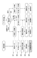
次に、感度データまたは折り返しデータの収集において更に時間短縮を可能にする本発明の第1の実施例について、図1を用いて説明する。この本発明の第1の実施例は、感度データを再計測することなく、計測済みの感度データを流用することにより撮影時間を短縮するものである。 Next, a first embodiment of the present invention that enables further time reduction in the collection of sensitivity data or aliasing data will be described with reference to FIG. In the first embodiment of the present invention, the photographing time is shortened by diverting the measured sensitivity data without re-measuring the sensitivity data.
図1(a)は、プリスキャンキャリブレーション法における第1の実施例を示す処理フロー図である。プリスキャンキャリブレーション法の場合、1回目のパラレルイメージングでは、プリスキャンにおいて感度データ101を収集し、本計測で折り返しデータ102を収集する。その後、再構成にて感度分布を計算103し、信号を合成104して画像を表示105する。2回目のパラレルイメージングを行う場合、再度感度データを収集することなく、折り返しデータの収集のみで折り返し除去を行うために、前回収集した感度データを流用することが可能であるか判定を行う(106)(再計測データ選択手段)。流用可能な場合の条件は、例えば、以下の様な条件が挙げられる。なお、この例により本発明が限定されるものではない。
FIG. 1 (a) is a processing flowchart showing a first embodiment of the pre-scan calibration method. In the case of the prescan calibration method, in the first parallel imaging, the
感度データの流用条件・・・前回感度データを収集した時と、
同一スライス位置かつ同一FOV
上記条件を満たして、感度データの流用を行う場合は、プリスキャンで感度データを収集することなく、本計測で折り返しデータのみを収集102して、前回の撮影で行った感度分布を用いて信号を合成104し、画像を表示105する。条件を満たさなかった場合は、1回目の撮影と同様の処理を繰り返す。
Sensitivity data diversion conditions: When the previous sensitivity data was collected,
Same slice position and same FOV
If the above conditions are met and sensitivity data is used, sensitivity data is not collected by pre-scan, but only return data is collected in this measurement. Are combined 104 and an image is displayed 105. If the condition is not met, the same processing as the first shooting is repeated.
また、図1(b)は、セルフキャリブレーション法における第1の実施例を示す処理フロー図である。セルフキャリブレーション法の場合、1回目のパラレルイメージングでは、本計測にて感度データと折り返しデータを同時に収集107し、再構成で感度分布を計算108して信号を合成109し、画像を表示110する。2回目以降の撮影は、流用条件を満たしているか判別を行い(110)、満たしていた場合、本計測で折り返しデータのみを収集112した後、1回目の撮影で行った感度分布を用いて信号を合成し、画像を表示する。流用不可の場合は、1回目の撮影と同様の処理を繰り返す。
FIG. 1B is a process flow diagram showing a first embodiment of the self-calibration method. In the case of the self-calibration method, in the first parallel imaging, sensitivity data and aliasing data are collected 107 simultaneously in the main measurement, sensitivity distribution is calculated by
尚、上記のように既に収集済みの感度データを流用することができる場合は流用する方法と、従来法のように次の撮影では必ず再度感度データを収集し直す方法の何れかを選択することを可能とする。 As described above, if the already collected sensitivity data can be diverted, select either the diversion method or the method of recollecting the sensitivity data again in the next shooting as in the conventional method. Is possible.
次に、感度データまたは折り返しデータのいずれか一方を再計測しないことによって更に時間短縮を可能にする本発明の第2の実施例について、図8を用いて説明する。この本発明の第2の実施例は、再計測しなくて良い方を自動または手動で選択するものである。 Next, a second embodiment of the present invention that enables further time reduction by not re-measuring either sensitivity data or aliasing data will be described with reference to FIG. In the second embodiment of the present invention, the one that does not need to be re-measured is automatically or manually selected.
図8は、プリスキャンキャリブレーション法で再構成後の画像が良好でない場合、最初から計測し直すのではなく、感度データ又は折り返しデータの一方のみを計測し直すことにより良好な画像を得ることを可能とする処理フロー図である。 Figure 8 shows that if the image after reconstruction by the pre-scan calibration method is not good, a good image can be obtained by re-measuring only one of the sensitivity data or the aliasing data instead of re-measuring from the beginning. It is a processing flow figure made possible.
点線部の感度データ801と折り返しデータ802は、以前収集したデータを流用したもの、または再度収集し直したものである。この感度データ801により感度分布を計算し(803)、信号を合成して(804)画像を表示(805)したところ、結果画像が好ましくなかった場合、次に記述する判断を行うことにより感度データまたは折り返しデータどちらか一方のみ、又は両方のデータを自動または手動で計測し直すものである(806)。まず、自動検出によりシステムがどちらか一方、又は両方を再計測すべきかを画像を表示すると共に操作者に推薦し、操作者は画像とシステムからの推薦を合わせて検討してどちらか一方、又は両方を再計測するかを指示する。その指示に従って、選択された方を再計測するという流れとなる。なお、操作者の判断を行うことなく、自動検出によって選択された方を自動で再計測しても良い。
Dotted
以上のように、自動または手動で指示を出し、片方のみ又は両方のデータを再計測することによって、全データを計測し直すよりも短時間で再撮影する。上記の、どちらのデータを再計測するべきか自動で検出する方法を、図9〜10に示す例を用いて説明する。
尚、両方のデータを計測する場合は従来と同様なので、以下省略する。
As described above, an instruction is issued automatically or manually, and only one or both of the data is re-measured, so that re-imaging is performed in a shorter time than re-measurement of all the data. A method for automatically detecting which data should be re-measured will be described with reference to examples shown in FIGS.
In addition, since it is the same as that of the past when measuring both data, it abbreviate | omits below.
まず、感度データのみを計測し直す場合の一例として、腹部撮影の息止め計測を挙げる。感度データ計測時に息止めを行い、計測後自由呼吸とし、折り返しデータ計測時に再度息止めを行った場合、各データ計測時の息止めレベルの差異により腹部の位置が異なってしまい、完全にパラレル展開ができず折り返しが強く残ることがある。この場合、折り返しデータ計測時と同じレベルで息止めして感度データを計測し直し、それを用いて先ほど計測した折り返しデータをパラレル展開することによって、正確に折り返しを除去することが可能となる。 First, as an example of re-measuring only sensitivity data, a breath holding measurement for abdominal radiography is given. If you hold your breath when you measure sensitivity data, and you take a free breath after the measurement, and then hold your breath again when you measure the return data, the abdomen position will be different due to the difference in the breath-hold level at each data measurement, and it will be completely parallel May not be able to fold and the return may remain strong. In this case, it is possible to accurately remove the aliasing by holding the breath at the same level as when the aliasing data is measured and measuring the sensitivity data again and using the aliasing data measured earlier in parallel.
この取り直し条件としては、例えば重心法により感度データ・折り返しデータの位置ズレを自動検出する方法がある。重心法について、図9を用いて説明する。感度画像901と折り返し画像902、それぞれにおいて信号のある座標を抽出し、それらの座標の平均により各画像の中心を算出する(903,904)。各画像の中心の差が閾値内であるか判定(905)し、判定値より小さければ位置ずれなしと判断する(906)。また、判定値以上であった場合は、感度データと折り返しデータ間の画像の位置がずれていると判断し(907)、感度データのみを取り直しするよう推薦または指示する(908)。尚、判定値はユーザー入力を基に計算するか、内部的に設定する。
As this re-recovery condition, for example, there is a method of automatically detecting the positional deviation of sensitivity data and aliasing data by the center of gravity method. The centroid method will be described with reference to FIG. In the sensitivity image 901 and the folded
次に、折り返しデータのみを計測し直す場合の一例として、折り返しデータ計測中に被検体が動いた例を挙げる。折り返しデータの計測は感度データ計測時間より長いため、計測中に被検体が大きく動いてしまうことがある。この場合に、折り返しデータを再計測する必要があるが、特に被検体が動い後以降の折り返しデータを再計測することにより、トータルの撮影時間を短縮できる。計測中の動きを認識する方法としては、例えばナビゲーションエコーを用いることができる。 Next, an example in which only the return data is remeasured is an example in which the subject moves during the return data measurement. Since the measurement of the return data is longer than the sensitivity data measurement time, the subject may move greatly during the measurement. In this case, it is necessary to re-measure the return data, but the total imaging time can be shortened by re-measurement of the return data after the subject moves. As a method for recognizing movement during measurement, for example, navigation echo can be used.
ナビゲーションエコーを用いて体動を判定する処理の一例を、図10(a)のEPIシーケンスを例に用いて説明する。スライス選択傾斜磁場パルス1002と共に90°、180°の高周波(RF)パルス1001を印加し、被検体の特定の領域の核スピンを励起した後、位相エンコード傾斜磁場パルス1003を印加する前に、ナビゲーションエコー計測のため読み出し傾斜磁場パルス1004を印加し、ナビゲーションエコー信号1005を計測する。
An example of processing for determining body movement using navigation echo will be described using the EPI sequence of FIG. 10 (a) as an example. Applying 90 ° and 180 ° radio frequency (RF)
このように、プリスキャンと本計測でナビゲーションエコーデータ(以下、「Naviエコーデータ」という)を入れて計測を行い、各Naviエコーデータを一次元フーリエ変換することにより、一次位相傾斜1006を算出し、その平均を基準値とする(図10(b))。その基準値から本計測のNaviエコーデータの一次傾斜が閾値を超えるもの(図10(b)ではα6)の個数を計測し(1007)、閾値から外れているαの数と設定値を比較して(1008)、設定値より少ない場合は位置ずれなしと判断する(1009)。設定値以上だった場合は、位置ずれありと判断し(1010)、折り返しデータの取り直しを行うよう推薦または指示する(1011)。尚、閾値や設定値はユーザー入力を基に計算するか、内部的に設定する。
In this way, navigation echo data (hereinafter referred to as “Navi echo data”) is measured in the pre-scan and main measurement, and the
上記の例のように自動検出を行うが、この結果を参考にして操作者が画像を見てから取り直しを指示する場合は、折り返しアーチファクトやモーションアーチファクト等の程度によって再計測するか否か、また何れのデータにおいて行うかを判断する。 Although automatic detection is performed as in the above example, if the operator instructs re-taking after viewing the image with reference to this result, whether or not to re-measure depending on the degree of folding artifacts, motion artifacts, etc. Which data is used for determination is determined.
以上の感度データを再計測せずに、既存の感度データを流用して撮像時間を短縮することは、同一の計測を複数回繰り返す、ダイナミックスキャンやフルオロスコピー計測においても適用可能で、特に2回目以降の撮影を高速に行うことが可能となる。 Reducing the imaging time by reusing existing sensitivity data without re-measuring the above sensitivity data is also applicable to dynamic scan and fluoroscopy measurement, which repeats the same measurement multiple times, especially the second time. Subsequent shooting can be performed at high speed.
708…被検体、701…静磁場発生系、702…傾斜磁場発生系、706…シーケンサ、703…送信系、704…受信系、705…信号処理系、707…中央処理装置(CPU)、709…傾斜磁場コイル、710…傾斜磁場電源、711…高周波発振器、712…変調器、713…高周波増幅器、714…照射コイル(送信側)、715…受信コイル(受信側)、716…受信回路、717…A/D変換器、718…信号処理装置、720…磁気ディスク、721…光ディスク、722…ディスプレイ 708 ... subject, 701 ... static magnetic field generation system, 702 ... gradient magnetic field generation system, 706 ... sequencer, 703 ... transmission system, 704 ... reception system, 705 ... signal processing system, 707 ... central processing unit (CPU), 709 ... Gradient magnetic field coil, 710 ... Gradient magnetic field power supply, 711 ... High frequency oscillator, 712 ... Modulator, 713 ... High frequency amplifier, 714 ... Irradiation coil (transmission side), 715 ... Reception coil (reception side), 716 ... Reception circuit, 717 ... A / D converter, 718 ... signal processing device, 720 ... magnetic disk, 721 ... optical disk, 722 ... display
Claims (6)
核磁気共鳴により前記被検体から放出されるエコー信号を検出する複数のRF受信コイルからなるマルチプルRF受信コイルを備えて、前記RF受信コイル毎の感度データと、計測空間の位相エンコードステップが間引かれた画像用データとを計測するエコー信号受信手段と、
前記RF受信コイル毎の前記画像用データと前記感度データとを用いて、パラレルイメージングに基づく演算により画像を取得する信号処理手段と、
前記エコー信号を受信するパルスシーケンスを制御するパルスシーケンス制御手段と、を備えた磁気共鳴イメージング装置において、
前記感度データと前記画像用データのどちらか一方又は両方のデータを再計測するか否かを選択する再計測データ選択手段を備え、該再計測データ選択手段によって選択されたデータを再計測することを特徴とする磁気共鳴イメージング装置。 A static magnetic field generating means for applying a static magnetic field to a subject; a gradient magnetic field generating means for applying a gradient magnetic field in a slice direction, a phase encoding direction, and a frequency encoding direction; and a high frequency magnetic field for inducing nuclear magnetic resonance in a nuclear spin in the subject A high-frequency magnetic field transmitting means for irradiating a pulse;
A multiple RF receiving coil comprising a plurality of RF receiving coils for detecting echo signals emitted from the subject by nuclear magnetic resonance is provided, and the sensitivity data for each RF receiving coil and the phase encoding step of the measurement space are thinned out. Echo signal receiving means for measuring the image data,
Signal processing means for acquiring an image by calculation based on parallel imaging using the image data and the sensitivity data for each RF receiving coil;
In a magnetic resonance imaging apparatus comprising: a pulse sequence control unit that controls a pulse sequence for receiving the echo signal;
Re-measurement data selection means for selecting whether to re-measure one or both of the sensitivity data and the image data, and re-measure the data selected by the re-measurement data selection means A magnetic resonance imaging apparatus.
Priority Applications (1)
| Application Number | Priority Date | Filing Date | Title |
|---|---|---|---|
| JP2003279564A JP4202855B2 (en) | 2003-07-25 | 2003-07-25 | Magnetic resonance imaging system |
Applications Claiming Priority (1)
| Application Number | Priority Date | Filing Date | Title |
|---|---|---|---|
| JP2003279564A JP4202855B2 (en) | 2003-07-25 | 2003-07-25 | Magnetic resonance imaging system |
Publications (3)
| Publication Number | Publication Date |
|---|---|
| JP2005040464A JP2005040464A (en) | 2005-02-17 |
| JP2005040464A5 JP2005040464A5 (en) | 2006-09-07 |
| JP4202855B2 true JP4202855B2 (en) | 2008-12-24 |
Family
ID=34265635
Family Applications (1)
| Application Number | Title | Priority Date | Filing Date |
|---|---|---|---|
| JP2003279564A Expired - Lifetime JP4202855B2 (en) | 2003-07-25 | 2003-07-25 | Magnetic resonance imaging system |
Country Status (1)
| Country | Link |
|---|---|
| JP (1) | JP4202855B2 (en) |
Cited By (1)
| Publication number | Priority date | Publication date | Assignee | Title |
|---|---|---|---|---|
| CN110055756B (en) * | 2019-05-07 | 2022-02-18 | 四川丝玛帛科技有限公司 | Multi-dimensional crosslinking glue fixing method for silk |
Families Citing this family (11)
| Publication number | Priority date | Publication date | Assignee | Title |
|---|---|---|---|---|
| JP5037866B2 (en) * | 2006-06-28 | 2012-10-03 | 株式会社日立メディコ | Magnetic resonance imaging system |
| JP4901420B2 (en) * | 2006-10-20 | 2012-03-21 | ジーイー・メディカル・システムズ・グローバル・テクノロジー・カンパニー・エルエルシー | Magnetic resonance imaging apparatus and magnetic resonance imaging method |
| JP2010005232A (en) * | 2008-06-30 | 2010-01-14 | Ge Medical Systems Global Technology Co Llc | Mri system |
| WO2010107041A1 (en) * | 2009-03-18 | 2010-09-23 | 株式会社 日立メディコ | Magnetic resonance imaging device and method |
| JP5536358B2 (en) * | 2009-03-31 | 2014-07-02 | 株式会社日立メディコ | Magnetic resonance imaging apparatus and sensitivity correction method |
| US10067213B2 (en) * | 2010-12-22 | 2018-09-04 | Koninklijke Philips N.V. | Parallel MRI method using calibration scan, coil sensitivity maps and navigators for rigid motion compensation |
| JP6042069B2 (en) * | 2012-01-25 | 2016-12-14 | 東芝メディカルシステムズ株式会社 | Magnetic resonance imaging system |
| WO2015082236A1 (en) | 2013-12-05 | 2015-06-11 | Koninklijke Philips N.V. | Method of operating a magnetic resonance imaging system regarding detection of changes of at least one parameter having an influence on acquiring magnetic resonance images, particularly between a preparatory phase and a phase of acquiring magnetic resonance signals |
| JP6462211B2 (en) * | 2013-12-24 | 2019-01-30 | キヤノンメディカルシステムズ株式会社 | Magnetic resonance imaging apparatus and magnetic resonance imaging method |
| JP6697276B2 (en) * | 2016-01-26 | 2020-05-20 | キヤノンメディカルシステムズ株式会社 | Magnetic resonance imaging equipment |
| EP3460501B1 (en) | 2017-09-25 | 2021-11-24 | Siemens Healthcare GmbH | Mr layer-multiplexing method |
-
2003
- 2003-07-25 JP JP2003279564A patent/JP4202855B2/en not_active Expired - Lifetime
Cited By (1)
| Publication number | Priority date | Publication date | Assignee | Title |
|---|---|---|---|---|
| CN110055756B (en) * | 2019-05-07 | 2022-02-18 | 四川丝玛帛科技有限公司 | Multi-dimensional crosslinking glue fixing method for silk |
Also Published As
| Publication number | Publication date |
|---|---|
| JP2005040464A (en) | 2005-02-17 |
Similar Documents
| Publication | Publication Date | Title |
|---|---|---|
| US9575153B2 (en) | MR imaging using a multi-point dixon technique | |
| JP3952247B2 (en) | Nuclear magnetic resonance imaging system | |
| JP6243522B2 (en) | Parallel MRI with multi-echo Dixon water-fat separation and B0 distortion correction using regularized detection reconstruction | |
| EP2411829B1 (en) | Mr imaging using parallel signal acquisition | |
| JP5599893B2 (en) | MR imaging using navigator | |
| JP6333293B2 (en) | Metal resistant MR imaging | |
| US20030052676A1 (en) | Magnetic resonance imaging method and apparatus | |
| US20020190714A1 (en) | Motion correction of magnetic resonance images | |
| JP4202855B2 (en) | Magnetic resonance imaging system | |
| JP4698231B2 (en) | Magnetic resonance diagnostic equipment | |
| JP4679158B2 (en) | Magnetic resonance imaging system | |
| JP4072879B2 (en) | Nuclear magnetic resonance imaging system | |
| US10859652B2 (en) | MR imaging with dixon-type water/fat separation | |
| JP2021505296A (en) | Diffusion MR imaging with fat suppression | |
| JP4675936B2 (en) | Nuclear magnetic resonance imaging system | |
| JP3983792B2 (en) | Nuclear magnetic resonance imaging system | |
| JP3952310B2 (en) | Nuclear magnetic resonance imaging system | |
| US20240069136A1 (en) | Mr mammography | |
| JP4906952B2 (en) | Nuclear magnetic resonance imaging system | |
| JP4817381B2 (en) | Magnetic resonance imaging system |
Legal Events
| Date | Code | Title | Description |
|---|---|---|---|
| A521 | Request for written amendment filed |
Free format text: JAPANESE INTERMEDIATE CODE: A523 Effective date: 20060724 |
|
| A621 | Written request for application examination |
Free format text: JAPANESE INTERMEDIATE CODE: A621 Effective date: 20060724 |
|
| A977 | Report on retrieval |
Free format text: JAPANESE INTERMEDIATE CODE: A971007 Effective date: 20080805 |
|
| A131 | Notification of reasons for refusal |
Free format text: JAPANESE INTERMEDIATE CODE: A131 Effective date: 20080811 |
|
| A521 | Request for written amendment filed |
Free format text: JAPANESE INTERMEDIATE CODE: A523 Effective date: 20080903 |
|
| TRDD | Decision of grant or rejection written | ||
| A01 | Written decision to grant a patent or to grant a registration (utility model) |
Free format text: JAPANESE INTERMEDIATE CODE: A01 Effective date: 20080929 |
|
| A01 | Written decision to grant a patent or to grant a registration (utility model) |
Free format text: JAPANESE INTERMEDIATE CODE: A01 |
|
| A61 | First payment of annual fees (during grant procedure) |
Free format text: JAPANESE INTERMEDIATE CODE: A61 Effective date: 20081009 |
|
| R150 | Certificate of patent or registration of utility model |
Ref document number: 4202855 Country of ref document: JP Free format text: JAPANESE INTERMEDIATE CODE: R150 Free format text: JAPANESE INTERMEDIATE CODE: R150 |
|
| FPAY | Renewal fee payment (event date is renewal date of database) |
Free format text: PAYMENT UNTIL: 20111017 Year of fee payment: 3 |
|
| FPAY | Renewal fee payment (event date is renewal date of database) |
Free format text: PAYMENT UNTIL: 20111017 Year of fee payment: 3 |
|
| FPAY | Renewal fee payment (event date is renewal date of database) |
Free format text: PAYMENT UNTIL: 20121017 Year of fee payment: 4 |
|
| FPAY | Renewal fee payment (event date is renewal date of database) |
Free format text: PAYMENT UNTIL: 20121017 Year of fee payment: 4 |
|
| FPAY | Renewal fee payment (event date is renewal date of database) |
Free format text: PAYMENT UNTIL: 20131017 Year of fee payment: 5 |
|
| S111 | Request for change of ownership or part of ownership |
Free format text: JAPANESE INTERMEDIATE CODE: R313111 |
|
| S533 | Written request for registration of change of name |
Free format text: JAPANESE INTERMEDIATE CODE: R313533 |
|
| R350 | Written notification of registration of transfer |
Free format text: JAPANESE INTERMEDIATE CODE: R350 |
|
| R250 | Receipt of annual fees |
Free format text: JAPANESE INTERMEDIATE CODE: R250 |
|
| S111 | Request for change of ownership or part of ownership |
Free format text: JAPANESE INTERMEDIATE CODE: R313111 |
|
| R350 | Written notification of registration of transfer |
Free format text: JAPANESE INTERMEDIATE CODE: R350 |
|
| R250 | Receipt of annual fees |
Free format text: JAPANESE INTERMEDIATE CODE: R250 |
|
| EXPY | Cancellation because of completion of term |