JP4698231B2 - Magnetic resonance diagnostic equipment - Google Patents
Magnetic resonance diagnostic equipment Download PDFInfo
- Publication number
- JP4698231B2 JP4698231B2 JP2005009382A JP2005009382A JP4698231B2 JP 4698231 B2 JP4698231 B2 JP 4698231B2 JP 2005009382 A JP2005009382 A JP 2005009382A JP 2005009382 A JP2005009382 A JP 2005009382A JP 4698231 B2 JP4698231 B2 JP 4698231B2
- Authority
- JP
- Japan
- Prior art keywords
- magnetic field
- image
- sensitivity distribution
- calculation
- data
- Prior art date
- Legal status (The legal status is an assumption and is not a legal conclusion. Google has not performed a legal analysis and makes no representation as to the accuracy of the status listed.)
- Expired - Fee Related
Links
Images


Description
本発明は、核磁気共鳴を利用して核の密度分布や緩和時間分布等を映像化する磁気共鳴イメージング装置(以下、MRI装置という)に係り、特に複数のRF受信コイルを用いるとともに、位相エンコードを間引いて取得した信号を各RF受信コイルの感度分布を用いて行列演算により展開する撮影法(パラレルイメージング法)を適用したMRI装置に関する。 The present invention relates to a magnetic resonance imaging apparatus (hereinafter referred to as an MRI apparatus) that uses nuclear magnetic resonance to visualize nuclear density distribution, relaxation time distribution, and the like, and in particular, uses a plurality of RF receiving coils and phase encoding. The present invention relates to an MRI apparatus to which an imaging method (parallel imaging method) in which a signal obtained by thinning out is developed by matrix calculation using sensitivity distribution of each RF receiving coil.
MRI装置において被検体から発生するNMR信号を検出する受信コイルとして、近年、小型コイルを複数個並べた高感度なマルチプルコイル或いはフェイズドアレイコイルが多用されている。またこのようなマルチプルコイルを利用した、位相エンコード方向のデータを間引いた撮影法が提案されている(例えば、非特許文献1、非特許文献2など)。 In recent years, as a receiving coil for detecting NMR signals generated from a subject in an MRI apparatus, a highly sensitive multiple coil or phased array coil in which a plurality of small coils are arranged is frequently used. In addition, an imaging method using such multiple coils and thinning out data in the phase encoding direction has been proposed (for example, Non-Patent Document 1, Non-Patent Document 2, etc.).
この方法はパラレルイメージングと呼ばれ、マルチプルコイルを構成する小型コイルの感度分布がお互いに空間的に異なることを利用して位相エンコードデータを間引いた際に生じる折り返しを演算によって除去する。パラレルイメージングの演算に用いるRFコイル感度分布は、各RFコイルから求めることができ、具体的には、均一濃度のファントムの画像から、その投影した空間的シェーディングを感度分布とする方法、被検体を感度用に撮影して得た画像データに低周波フィルタを作用させたものを感度分布とする方法がある。さらに特許文献1では、断面像を取得する本計測のデータの一部を感度分布用に利用する手法を提案している。
ところで一般にRFコイルの空間感度分布は、コイルに近い部分が高感度となりコイルから離れるにしたがって低感度となる。このような特性のあるRFコイルから得られる画像は、RFコイルに近い部分は高輝度に、RFコイルから遠い部分が低輝度のデータとなり感度むらを生じる。従来、このような感度むらを除去するために、画像データに空間感度分布に応じた重み付けを行い受信コイル感度補正を行っている。感度補正演算では、通常画像データを逆フーリエ変換した後、ローパスフィルタ処理し、さらにフーリエ変換を行って空間感度分布を求める。 By the way, in general, the spatial sensitivity distribution of the RF coil has a high sensitivity at a portion close to the coil, and a low sensitivity as the distance from the coil increases. In an image obtained from an RF coil having such characteristics, the portion near the RF coil has high luminance, and the portion far from the RF coil has low luminance, resulting in uneven sensitivity. Conventionally, in order to eliminate such sensitivity unevenness, the image data is weighted in accordance with the spatial sensitivity distribution to perform reception coil sensitivity correction. In the sensitivity correction calculation, normal image data is subjected to inverse Fourier transform, then subjected to low-pass filter processing, and further subjected to Fourier transform to obtain a spatial sensitivity distribution.
上述したパラレルイメージングは位相エンコードを間引いた撮影であって撮像時間の短縮に有効であるが、このパラレルイメージングに感度補正を適用した場合、パラレルイメージングに伴う折り返し除去演算に加えて、感度分布補正演算が必要となるため、画像再構成時間が延長してしまい、画像再構成時間を含めた全体的な撮影時間短縮の効果を阻害する。特にリアルタイムで連続撮影する場合にはリアルタイム性が損なわれることになる。
そこで本発明は、パラレルイメージングの撮像時間の短縮効果を損なうことなく、RFコイルの空間感度分布不均一による輝度むらを解消し、良好な画像を得ることが可能なMRI装置を提供することを目的とする。
The parallel imaging described above is an imaging with phase encoding thinned out and is effective for shortening the imaging time. However, when sensitivity correction is applied to this parallel imaging, sensitivity distribution correction calculation is performed in addition to aliasing removal calculation accompanying parallel imaging. Therefore, the image reconstruction time is extended, and the overall effect of shortening the photographing time including the image reconstruction time is hindered. Particularly, when real-time continuous shooting is performed, the real-time property is impaired.
Therefore, the present invention has an object to provide an MRI apparatus capable of eliminating luminance unevenness due to non-uniform spatial sensitivity distribution of RF coils and obtaining a good image without impairing the effect of shortening the imaging time of parallel imaging. And
上記課題を解決する本発明のMRI装置は、静磁場空間に置かれた被検体に高周波磁場を印加する送信手段と、前記静磁場空間に傾斜磁場を発生する傾斜磁場発生手段と、複数の小型コイルから構成される受信コイルを含み、被検体から発生するエコー信号を検出する受信手段と、所定のパルスシーケンスに従い、被検体への高周波磁場及び傾斜磁場の印加並びに被検体から発生したエコー信号の計測を制御するシーケンス制御手段と、計測したエコー信号を用いて被検体の画像を再構成する画像再構成手段とを備え、前記画像再構成手段が行なう処理は、各小型コイルの感度分布計算及び該感度分布を用いた被検体画像の再構成計算を含み、前記感度分布計算を前記シーケンス制御手段における画像用データ取得のためのシーケンスの実行中に行なうように前記シーケンス制御手段および画像再構成手段を制御する手段を備えたことを特徴とする。 An MRI apparatus of the present invention that solves the above-described problems includes a transmission unit that applies a high-frequency magnetic field to a subject placed in a static magnetic field space, a gradient magnetic field generation unit that generates a gradient magnetic field in the static magnetic field space, and a plurality of small-sized magnetic fields. A receiving means configured to include a receiving coil configured to detect an echo signal generated from the subject; and applying a high-frequency magnetic field and a gradient magnetic field to the subject and an echo signal generated from the subject according to a predetermined pulse sequence. A sequence control means for controlling the measurement, and an image reconstruction means for reconstructing the image of the subject using the measured echo signal, and the processing performed by the image reconstruction means includes sensitivity distribution calculation for each small coil and Including a reconstruction calculation of the subject image using the sensitivity distribution, and executing the sequence for obtaining the image data in the sequence control means using the sensitivity distribution calculation Characterized by comprising means for controlling the sequence control unit and image reconstruction means to perform the.
本発明のMRI装置において、画像再構成手段が行なう処理は、さらに再構成された画像の感度補正計算を含むことができ、該感度補正計算は前記小型コイルの感度分布計算により求めた各感度分布を合成した受信コイル全体の感度分布を用いるとともに、前記受信コイル全体の感度分布を合成する計算を画像用データ取得のためのシーケンスの実行中に行なう。 In the MRI apparatus of the present invention, the processing performed by the image reconstruction means can further include sensitivity correction calculation of the reconstructed image, and the sensitivity correction calculation is performed by each sensitivity distribution obtained by the sensitivity distribution calculation of the small coil. Is used during the execution of a sequence for acquiring image data. The sensitivity distribution of the entire receiving coil is combined and the sensitivity distribution of the entire receiving coil is combined.
また本発明のMRI装置において、例えば、シーケンス制御手段は、1枚の画像再構成に必要な位相エンコードのうち、高周波領域の位相エンコードが疎で、低周波領域の位相エンコードは密であるように傾斜磁場発生手段を制御した計測を行い、画像再構成手段は、前記計測により得られたデータから、全領域の位相エンコードが疎であるデータと、位相エンコードが密である低周波領域のデータとを作成し、位相エンコードが密である低周波領域のデータを用いて小型コイルの感度分布計算と受信コイル全体の感度分布を求める計算とを行なう。
或いは、シーケンス制御手段は、低周波領域の位相エンコードは密であるように傾斜磁場発生手段を制御した第1の計測と、1枚の画像再構成に必要な位相エンコードを所定の割合で間引くように傾斜磁場発生手段を制御した第2の計測を実行し、画像再構成手段は、前記第1の計測により得られたデータを用いて小型コイルの感度分布計算と受信コイル全体の感度分布を求める計算とを行なう。
Further, in the MRI apparatus of the present invention, for example, the sequence control means is such that the phase encoding in the high frequency region is sparse and the phase encoding in the low frequency region is dense among the phase encoding necessary for image reconstruction. The measurement is performed by controlling the gradient magnetic field generation means, and the image reconstruction means includes, from the data obtained by the measurement, data in which the phase encoding of the entire area is sparse and data in the low frequency area in which the phase encoding is dense. Are used to calculate the sensitivity distribution of the small coil and the sensitivity distribution of the entire receiving coil using the data in the low frequency region where the phase encoding is dense.
Alternatively, the sequence control means thins out the first measurement in which the gradient magnetic field generating means is controlled so that the phase encoding in the low frequency region is dense and the phase encoding necessary for one image reconstruction at a predetermined rate. The image reconstructing means obtains the sensitivity distribution calculation of the small coil and the sensitivity distribution of the entire receiving coil using the data obtained by the first measurement. Perform calculations.
本発明のMRI装置によれば、シーケンス制御部と画像再構成手段の動作を制御し、本計測を行なっている間に本計測に先立って収集された感度データを用いて感度分布計算を実行するので、本計測後直ちに該感度分布を用いた折り返し除去計算を行なうことができ、パラレルイメージングによる計測時間短縮の実効を得ることができる。
また本発明のMRI装置によれば、パラレルイメージングに用いた感度分布を利用して感度補正を行なうことができ、画質をさらに向上することができる。
According to the MRI apparatus of the present invention, the operation of the sequence control unit and the image reconstruction unit is controlled, and the sensitivity distribution calculation is executed using the sensitivity data collected prior to the main measurement during the main measurement. Therefore, the aliasing removal calculation using the sensitivity distribution can be performed immediately after the main measurement, and the measurement time can be effectively shortened by parallel imaging.
Further, according to the MRI apparatus of the present invention, sensitivity correction can be performed using the sensitivity distribution used for parallel imaging, and the image quality can be further improved.
以下、本発明の実施の形態を図面を参照して説明する。 Hereinafter, embodiments of the present invention will be described with reference to the drawings.
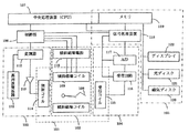
図1は、本発明が適用されるMRI装置の全体概要を示す図である。このMRI装置は、被検体108の周りの空間に静磁場を発生するための静磁場発生系101、その空間に傾斜磁場を加える傾斜磁場発生系102、被検体108の組織を構成する原子の原子核を励起して核磁気共鳴を起こさせるために高周波パルスを発生する送信系103、被検体108から発生する磁気共鳴によるエコー信号を受信する受信系104、エコー信号にフーリエ変換、補正計算等の処理を行なう信号処理系105、上記傾斜磁場発生系102、送信系103及び受信系104の動作を制御する制御部106、並びに信号処理系105及び制御部106に指令を送る中央処理装置(CPU)107を備えている。
FIG. 1 is a diagram showing an overall outline of an MRI apparatus to which the present invention is applied. This MRI apparatus includes a static magnetic
静磁場発生系101は、永久磁石、常電導磁石或いは超電導磁石などの磁場発生手段からなり、被検体108の体軸に沿った方向或いは体軸と直交する方向に均一な静磁場を発生させる。傾斜磁場発生系102は、X,Y,Zの3軸方向の傾斜磁場コイルからなり、この傾斜磁場の加え方により被検体108の撮像断面が設定されるとともに、エコー信号をエンコードし位置情報を付与することができる。
The static magnetic
送信系103は、高周波発振器111、変調器112、高周波増幅器113及び高周波照射コイル114からなり、高周波発振器111から出力された高周波パルスを高周波増幅器113で増幅した後に、被検体108に近接して配置された高周波照射コイル114に供給して被検体に照射する。
The
受信系104は、高周波受信コイル115、受信回路116及びA/D変換器117からなり、受信コイル115が受信したNMR信号を受信回路116で検波した後A/D変換器117でディジタル信号に変換し、制御部116からの命令によるタイミングでサンプリングされた収集データとして信号処理系105に送る。本発明のMRI装置では、パラレルイメージングを行なうために、受信コイルとして複数の小型受信コイル(以下、単に小型コイルという)からなる受信コイルが用いられている。このような受信コイルとして、マルチプルコイル或いはフェイズトアレイコイルと呼ばれる公知の受信コイル(例えば、非特許文献1〜3に記載のもの)を用いることができる。受信回路116及びA/D変換器117は、小型コイル毎に設けられている。
The
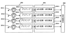
受信系104の構成を図2に示す。図示する実施形態では、受信コイルは4つの小型コイル2011〜2014からなり、それぞれプリアンプ2021〜2024に接続されて一つのマルチプルコイル203を構成する。受信回路204は、小型コイル毎のA/D変換器及び直交検波回路2051〜2054が並列したもので、プリアンプ2021〜2024の出力がそれぞれ接続されている。各小型コイル2011〜2014で検出されたNMR信号は、受信回路204で検波され、ディジタル複素信号に変換され、信号処理系206に送られる。
The configuration of the
信号処理系105(206)は、CPU107、受信系104から送られる収集データに対しフーリエ変換、補正計算、画像再構成などの演算を行なうとともに演算に必要な信号処理を行なう信号処理装置118、収集データを一時的に保管するとともに、経時的な画像解析処理及び指定されたパルスシーケンスのプログラムやその実行に用いられるパラメータ等を記憶するメモリ119、再構成された画像データを記憶するデータ格納部となる磁気ディスク120、光ディスク121等の記憶装置、画像データを画像として表示するディスプレイ122、及び図示していないがトラックボール、マウス、キーボードなどの操作部を備えている。
A signal processing system 105 (206) performs processing such as Fourier transform, correction calculation, and image reconstruction on the collected data sent from the
制御部106は、CPU107の制御で動作し、撮像方法によって決まる所定のパルスシーケンスに従って傾斜磁場発生系102、送信系103、受信系104及び信号処理系105が動作するようにこれらを制御する。CPU107は、操作部を介して選択される撮影モードに従って、シーケンスを制御する制御部106と画像再構成等の演算を行なう信号処理系(信号処理装置118)105の動作を制御する。本発明のMRI装置では、パラレルイメージング法を実行するための2つの計測モードが予め設定されている。一つは、被検体の画像を得るための計測(本計測)中に感度分布データを収集する計測モード(SCM:セルフキャリブレーションモード)であり、もう一つは本計測に先立って感度分布データを収集する計測モード(PCM:プリスキャンキャリブレーションモード)である。これらは、例えば操作部を介して選択することができ、またいずれの場合にも、感度分布データの収集が完了すると本計測と平行して感度分布計算を行なうように信号処理系107に指令を送る。
The
次に上記構成におけるMRI装置を用いたパラレルイメージング法による撮像方法の第1の実施形態を説明する。この実施形態では、被検体の断層像を得るためデータ(本計測データ)と感度分布データとを同時に取得する場合(SCM:セルフキャリブレーションモード)を説明する。 Next, a first embodiment of an imaging method based on a parallel imaging method using the MRI apparatus having the above configuration will be described. In this embodiment, a case (SCM: self-calibration mode) in which data (main measurement data) and sensitivity distribution data are acquired simultaneously to obtain a tomographic image of a subject will be described.
一般にパラレルイメージング法では、1枚の画像の再構成に必要な位相エンコードのエコーを計測せず、均等に位相エンコードを間引いた計測を行なう。原理的には受信コイルを構成する小型コイルの数をNとすると、1枚の画像再構成に必要な位相エンコード数の1/Nの位相エンコード数で計測することができる。この実施形態では、被検体の断層像を得るための計測(以下、本計測)においてパラレルイメージング法を適用して位相エンコードを間引くとともに、低周波領域については位相エンコードを間引かずにデータを計測し、この領域のデータを用いて感度分布計算を行なう。 In general, the parallel imaging method does not measure the phase-encoded echoes necessary for reconstructing one image, and performs measurement with the phase encoding thinned out evenly. In principle, if the number of small coils constituting the receiving coil is N, measurement can be performed with a phase encode number 1 / N of the number of phase encodes necessary for reconstruction of one image. In this embodiment, phase encoding is thinned out by applying a parallel imaging method in measurement for obtaining a tomographic image of a subject (hereinafter referred to as main measurement), and data is measured without thinning out phase encoding in a low frequency region. The sensitivity distribution is calculated using the data in this region.
本実施例で採用されるパルスシーケンスの一例を図3に示す。このパルスシーケンスは、グラディエントエコー法のシーケンスで、スライスエンコード傾斜磁場302と共にRFパルス301を印加し、被検体の特定領域の核スピンを励起して横磁化を発生させた後、位相エンコード傾斜磁場パルス303を印加し、ついで読み出し傾斜磁場パルス304を印加し、エコー信号305を計測する。RFパルス301印加からエコー信号305計測までの時間(エコー時間)TEは、画像コントラストを決めるパラメータであり、対象とする組織等を考慮して予め設定される。このシーケンスを位相エンコード傾斜磁場パルスの印加量(印加時間について磁場強度を積分した値)を変えながら、複数回繰り返し、k空間データを得る。この際、位相エンコードの変化の仕方を一様ではなく、位相エンコード量の大きい領域(k空間の高周波領域)ではパラレルイメージングで規定される所定の間引き率Nで位相エンコードを間引き(すなわち位相エンコード量を(N−1)ステップ分省きながら)計測し、小さい領域(k空間の低周波領域)では間引かずに計測する。
An example of the pulse sequence employed in this embodiment is shown in FIG. This pulse sequence is a gradient echo sequence. An
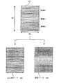
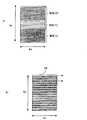
こうして計測したk空間データ配列を図4に示す。図中、計測されたデータは白で、計測されない(間引かれた)データは灰色で示している。k空間データは、横方向(kx方向)の一列のデータが1つのエコー信号から得られ、kyの値は位相エンコード量で決まる。1枚の画像を再構成するためには通常すべての位相エンコード量のデータが得られるが、本実施形態のシーケンスでは、図に示すように、k空間データ401のうち、高周波域bには計測されないデータが存在し、低周波域aは全てのデータが計測されている。k空間データを計測する順序(計測方法)には、いくつかの方法があるが、例えば、ここでは最も高周波域データから計測を開始し、低周波域を経て極性の異なる高周波域データまで順番に計測するシーケンシャルオーダーが採用されている。
FIG. 4 shows the k-space data array thus measured. In the figure, measured data is shown in white, and data not measured (thinned out) is shown in gray. As the k-space data, a row of data in the horizontal direction (kx direction) is obtained from one echo signal, and the value of ky is determined by the phase encoding amount. In order to reconstruct one image, data of all phase encoding amounts are usually obtained. However, in the sequence of this embodiment, as shown in the figure, the measurement is performed in the high-frequency region b of the k-
信号処理系105は、こうして収集されたデータ401を分けて二つのk空間データを作成する。一つはk空間領域全体で位相エンコードを等間隔で間引いた画像再構成用データ404とする。他の一つは低周波領域aのデータで構成される感度データ405とする。k空間の計測順序がシーケンシャルオーダリングの場合、k空間の全領域の計測が終了する前に感度データは収集されることになるので、感度データが収集されると直ちに感度分布の計算を行なう。
The
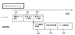
この様子を図5に示す。図中、横軸は時間で、シーケンスを制御する制御部106の動作501〜503と信号処理系105の動作504〜506がそれぞれブロックで示されている。図示するように、シーケンスはまず図4に示す領域bの計測(位相エンコードが疎となる部分のデータ計測)501を行い、次いで領域aの計測(位相エンコードが密である部分のデータ計測)502を行い、最後に残りの領域bの計測503を行なう。このシーケンスの進行において、領域aの計測503が終了した時点で感度データ405を用いて感度分布計算504を行い、領域bの計測503が終了した時点で計測501〜503で得られた本計測データ404と、感度分布計算504で求めた各小型コイルの感度分布を用いて、折り返しの除去された画像データを得る。最後に各小型コイルの感度分布を合成した受信コイル全体としての感度分布を用いて画像データのコイル感度補正506を行なう。
This is shown in FIG. In the figure, the horizontal axis is time, and the
信号処理系105が行なう感度分布計算、画像再構成演算及び感度補正計算は公知の手法を用いて行なうことができる。具体的には、感度分布の計算504は、ローパスフィルタ処理後、二次元フーリエ変換処理を行なうことにより得た画像データから求める。即ち、まず各小型コイルからの収集データを二次元フーリエ変換後の画素値(感度データ)wi(x,y)(添え字iはコイル番号を示す。以下同じ)を次式(数1)により合成する。

次に各小型コイルの感度データwi(x,y)をSc(x,y)で除算し、各小型コイルの感度画像Ci(x,y)を得る。
また折り返しを除去した画像P(x,y)を得る計算505は、画像再構成用データ404と上述の計算により得た各RFコイルの感度画像Ci(x,y)とを用いて以下のように行なう。即ち、計測データを1/Nに間引きした場合、画像の位相エンコード方向マトリックスはΔY=Y/Nとなり、RFコイルiの折り返し画像Si(x,y)は次式(数3)で表される。
感度補正506は、各小型コイルの感度分布を合成したものSc(x,y)を用いて、次式(数6)により行なう。
図6は、信号処理系が行なう上記処理を模式的に示したものであり、本実施形態によれば、時間のかかる感度分布作成処理600を本計測と並行して実行しているので、本計測データの収集が完了後、直ちに、処理600で得た小型コイルの感度分布6011〜6014を用いた折り返し除去計算(行列計算606、逆行列計算607)を行なうことができ、また感度分布作成処理600で作成した合成感度分布データ603を用いて、コイル感度補正608を行なうことができる。これによって感度補正された画質の優れた結果画像609が得られる。このように本実施形態によれば、演算量の増加に伴う画像形成の時間延長を防止することができ、パラレルイメージングの高速化を実効あらしめることができる。
FIG. 6 schematically shows the above processing performed by the signal processing system. According to the present embodiment, the time-consuming sensitivity
次に本発明の第2の実施形態として、プリスキャンキャリブレーションモード(PCM)の計測を説明する。PCMでは、感度データの取得は本計測のプリスキャンとして行なう。 Next, measurement of a prescan calibration mode (PCM) will be described as a second embodiment of the present invention. In PCM, sensitivity data is acquired as a pre-scan for the main measurement.
本実施形態においてもパルスシーケンスは第1の実施形態と同様のパルスシーケンスを採用することができる。但し、本計測に先立つ感度データを得るための計測は、k空間のうち低周波領域のデータのみを計測する。即ち、例えば図3に示すパルスシーケンスの繰り返しにおいて、位相エンコード傾斜磁場303を変化させる際に、位相エンコード量を最大値から最小値まで変化させるのではなく、0を中心とする狭い範囲で変化させる。
Also in the present embodiment, the same pulse sequence as in the first embodiment can be adopted as the pulse sequence. However, the measurement for obtaining the sensitivity data prior to the actual measurement measures only the data in the low frequency region of the k space. That is, for example, when the phase encoding gradient
こうして得られる感度データは、図7(a)に示すように、第1の実施形態で本計測データから分割したデータ(図4、405)と同じもので、高周波領域データ703(灰色で示す部分)を含まない低周波領域702のみのデータ(白で示す部分)である。この感度データは小型コイル毎に得られる。これら感度データを図6に示したように、第1の実施形態と同様に、ローパスフィルタ処理、2次元フーリエ変化処理を行なって画像化し、数1及び数2により各RFコイルの感度画像を得る。
一方、シーケンス制御部は感度データ取得のためのプリスキャンに続けて本計測を実行する。本計測では、受信コイルを構成する小型コイルの数で規定される所定の間引き率に従って位相エンコードを間引いた計測を行い、図7(b)に示すような本計測データ705を得る。
As shown in FIG. 7A, the sensitivity data thus obtained is the same as the data (FIG. 4, 405) divided from the main measurement data in the first embodiment, and the high-frequency region data 703 (the portion shown in gray) ) (Not shown in white) only in the low frequency region 702. This sensitivity data is obtained for each small coil. As shown in FIG. 6, the sensitivity data is imaged by performing low-pass filter processing and two-dimensional Fourier change processing, as in the first embodiment, and sensitivity images of the respective RF coils are obtained by Equations 1 and 2. .
On the other hand, the sequence control unit performs the main measurement following the pre-scan for obtaining sensitivity data. In the main measurement, measurement is performed by thinning out the phase encode according to a predetermined thinning rate defined by the number of small coils constituting the receiving coil, and
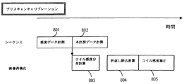
本実施形態における制御部の動作(シーケンス制御)801、802と信号処理系の動作(計算)803〜805の関係を図8に示す。図示するように、前述の信号処理系における感度分布計算803はこの本計測802と並行して行なわれる。従って本計測データの取得が完了した時点では、各小型コイルと受信コイル全体の感度分布が求められているので、信号処理系はまず各小型コイルの感度分布を用いて数3〜数5に従い本計測データの折り返し除去と画像再構成計算805を行い、ついで受信コイルの感度分布を用いて、数6に従い得られた画像の感度補正806を行なう。
FIG. 8 shows the relationship between the operations (sequence control) 801 and 802 of the control unit and the operations (calculations) 803 to 805 of the signal processing system in this embodiment. As shown in the figure, the
このように本実施形態においても、感度データ取得完了後、本計測と並行して感度分布計算を行なうことにより、本計測後直ちに折り返し除去計算、感度補正計算を行なうことができ、短時間で感度補正された良好な画像を得ることができる。 As described above, also in this embodiment, by performing sensitivity distribution calculation in parallel with the main measurement after the completion of the sensitivity data acquisition, the aliasing removal calculation and the sensitivity correction calculation can be performed immediately after the main measurement. A corrected good image can be obtained.
以上、本発明のMRI装置の動作をセルフキャリブレーションモードで行なう第1の実施形態とプリスキャンキャリブレーションモードで行なう第2の実施形態を用いて説明したが、本発明のMRI装置は、これら2つのモードを適宜選択して実行することが可能である。また感度データ計測及び本計測で実行するパルスシーケンスとしては、図3に示すグラディエントエコー法によるパルスシーケンスに限定されることなく、撮影対象とする組織や部位に応じて適宜公知の撮像シーケンス、例えばスピンエコーシーケンス、高速スピンエコーシーケンス、EPIシーケンス、スパイラルシーケンス、SSFPシーケンスなどを採用すること可能である。 The operation of the MRI apparatus of the present invention has been described using the first embodiment in which the operation is performed in the self-calibration mode and the second embodiment in which the operation is performed in the pre-scan calibration mode. It is possible to select and execute one mode as appropriate. Further, the pulse sequence executed in the sensitivity data measurement and the main measurement is not limited to the pulse sequence by the gradient echo method shown in FIG. 3, and a known imaging sequence, for example, a spin according to the tissue or region to be imaged. An echo sequence, a high-speed spin echo sequence, an EPI sequence, a spiral sequence, an SSFP sequence, or the like can be employed.
本発明によれば、リアルタイム性に優れ、体動による画像劣化を効果的に抑制できるパラレルイメージング法を採用するMRI装置において、パラレルイメージングの演算に必要な感度データを本計測と並行して取得すると共に、その後の感度補正にも適用することにより、短時間で感度補正された画像を得ることができる。また時間短縮分を利用して、空間分解能の向上やスライス枚数の増加など用途に応じた様々な適用が可能である。 According to the present invention, in an MRI apparatus that employs a parallel imaging method that has excellent real-time properties and can effectively suppress image degradation due to body movement, sensitivity data necessary for parallel imaging calculation is acquired in parallel with the main measurement. At the same time, by applying it to subsequent sensitivity correction, an image whose sensitivity is corrected can be obtained in a short time. In addition, by using the time reduction, various applications such as an improvement in spatial resolution and an increase in the number of slices can be applied depending on the application.
101・・・静磁場発生系、102・・・傾斜磁場発生系、103・・・送信系、104・・・受信系、105・・・信号処理系、115、203・・・受信コイル、2011〜2014・・・小型受信コイル
101 ... Static magnetic field generation system, 102 ... Gradient magnetic field generation system, 103 ... Transmission system, 104 ... Reception system, 105 ... Signal processing system, 115, 203 ... Reception coil, 2011 ~ 2014 ・ ・ ・ Small receiver coil
Claims (3)
前記シーケンス制御手段は、1枚の画像再構成に必要な位相エンコードのうち、k空間の高周波領域の位相エンコードが疎で、k空間の低周波領域の位相エンコードは密であるように傾斜磁場発生手段を制御した計測を行い、
前記画像再構成手段が行なう処理は、各小型コイルの感度分布計算、該感度分布を用いた被検体画像の再構成計算、及び再構成された画像の感度補正計算を含み、
前記画像再構成手段は、前記感度分布計算を、画像用データのうち位相エンコードが疎であるk空間の高周波領域の計測中に行ない、
前記感度分布計算により求めた各小型コイルの感度分布を合成して受信コイル全体の感度分布を求め、当該受信コイル全体の感度分布を用いて、直前に再構成された画像の前記感度補正計算を行うことを特徴とする磁気共鳴診断装置。 A subject including a transmitting means for applying a high-frequency magnetic field to a subject placed in a static magnetic field space; a gradient magnetic field generating means for generating a gradient magnetic field in the static magnetic field space; and a receiving coil comprising a plurality of small coils. Receiving means for detecting an echo signal generated from the signal, sequence control means for controlling the application of a high-frequency magnetic field and a gradient magnetic field to the subject and the measurement of the echo signal generated from the subject according to a predetermined pulse sequence, and the measured echo In a magnetic resonance diagnostic apparatus comprising image reconstruction means for reconstructing an image of a subject using a signal,
The sequence control means generates a gradient magnetic field so that the phase encoding of the high frequency region of k space is sparse and the phase encoding of the low frequency region of k space is dense among the phase encoding necessary for image reconstruction of one sheet. Measure the controlled means,
The processing performed by the image reconstruction means includes sensitivity distribution calculation of each small coil, reconstruction calculation of the subject image using the sensitivity distribution, and sensitivity correction calculation of the reconstructed image,
The image reconstruction means performs the sensitivity distribution calculation during measurement of a high-frequency region of k space in which phase encoding is sparse among image data,
The sensitivity distribution of each small coil obtained by the sensitivity distribution calculation is synthesized to obtain the sensitivity distribution of the entire receiving coil, and the sensitivity correction calculation of the image reconstructed immediately before is performed using the sensitivity distribution of the entire receiving coil. A magnetic resonance diagnostic apparatus characterized by being performed.
前記画像再構成手段は、前記計測により得られたデータから、位相エンコードが疎であるk空間全領域のデータと、位相エンコードが密であるk空間の低周波領域のデータとを作成し、位相エンコードが密であるk空間の低周波領域のデータを用いて前記小型コイルの感度分布計算と前記受信コイル全体の感度分布を求める計算とを行なうことを特徴とする請求項1記載の磁気共鳴診断装置。The image reconstruction means creates, from the data obtained by the measurement, data of the entire k-space where the phase encoding is sparse and data of the low frequency region of the k-space where the phase encoding is dense. 2. The magnetic resonance diagnosis according to claim 1, wherein the sensitivity distribution calculation of the small coil and the calculation of obtaining the sensitivity distribution of the entire receiving coil are performed using data in a low-frequency region of k-space with dense encoding. apparatus.
前記シーケンス制御手段は、k空間の低周波領域の位相エンコードは密であるように傾斜磁場発生手段を制御した第1の計測と、1枚の画像再構成に必要な位相エンコードを所定の割合で間引くように傾斜磁場発生手段を制御した第2の計測を実行し、
前記画像再構成手段が行なう処理は、各小型コイルの感度分布計算、該感度分布を用いた被検体画像の再構成計算、及び再構成された画像の感度補正計算を含み、
前記画像再構成手段は、前記第1の計測により得られたデータを用いて、前記小型コイルの感度分布計算と前記受信コイル全体の感度分布を求める計算とを、第2の計測中に行ない、
当該受信コイル全体の感度分布を用いて、直前に再構成された画像の前記感度補正計算を行なうことを特徴とする磁気共鳴診断装置。 A subject including a transmitting means for applying a high-frequency magnetic field to a subject placed in a static magnetic field space; a gradient magnetic field generating means for generating a gradient magnetic field in the static magnetic field space; and a receiving coil comprising a plurality of small coils. Receiving means for detecting an echo signal generated from the signal, sequence control means for controlling the application of a high-frequency magnetic field and a gradient magnetic field to the subject and the measurement of the echo signal generated from the subject according to a predetermined pulse sequence, and the measured echo In a magnetic resonance diagnostic apparatus comprising image reconstruction means for reconstructing an image of a subject using a signal,
The sequence control means performs the first measurement in which the gradient magnetic field generating means is controlled so that the phase encoding in the low frequency region of the k space is dense and the phase encoding necessary for one image reconstruction at a predetermined ratio. Execute the second measurement in which the gradient magnetic field generating means is controlled so as to be thinned out;
The processing performed by the image reconstruction means includes sensitivity distribution calculation of each small coil, reconstruction calculation of the subject image using the sensitivity distribution, and sensitivity correction calculation of the reconstructed image,
The image reconstruction means performs, during the second measurement, the sensitivity distribution calculation of the small coil and the calculation for obtaining the sensitivity distribution of the entire receiving coil using the data obtained by the first measurement .
A magnetic resonance diagnostic apparatus characterized in that the sensitivity correction calculation of the image reconstructed immediately before is performed using the sensitivity distribution of the entire receiving coil .
Priority Applications (1)
| Application Number | Priority Date | Filing Date | Title |
|---|---|---|---|
| JP2005009382A JP4698231B2 (en) | 2004-06-11 | 2005-01-17 | Magnetic resonance diagnostic equipment |
Applications Claiming Priority (3)
| Application Number | Priority Date | Filing Date | Title |
|---|---|---|---|
| JP2004174635 | 2004-06-11 | ||
| JP2004174635 | 2004-06-11 | ||
| JP2005009382A JP4698231B2 (en) | 2004-06-11 | 2005-01-17 | Magnetic resonance diagnostic equipment |
Publications (3)
| Publication Number | Publication Date |
|---|---|
| JP2006021023A JP2006021023A (en) | 2006-01-26 |
| JP2006021023A5 JP2006021023A5 (en) | 2008-02-07 |
| JP4698231B2 true JP4698231B2 (en) | 2011-06-08 |
Family
ID=35794700
Family Applications (1)
| Application Number | Title | Priority Date | Filing Date |
|---|---|---|---|
| JP2005009382A Expired - Fee Related JP4698231B2 (en) | 2004-06-11 | 2005-01-17 | Magnetic resonance diagnostic equipment |
Country Status (1)
| Country | Link |
|---|---|
| JP (1) | JP4698231B2 (en) |
Families Citing this family (8)
| Publication number | Priority date | Publication date | Assignee | Title |
|---|---|---|---|---|
| JP5248010B2 (en) * | 2006-02-17 | 2013-07-31 | 株式会社東芝 | Data correction apparatus, data correction method, magnetic resonance imaging apparatus, and X-ray CT apparatus |
| CN100591269C (en) * | 2006-02-17 | 2010-02-24 | 株式会社东芝 | Data correction apparatus, data correction method, magnetic resonance imaging apparatus and X-ray CT apparatus |
| JP5037866B2 (en) * | 2006-06-28 | 2012-10-03 | 株式会社日立メディコ | Magnetic resonance imaging system |
| JP4980662B2 (en) * | 2006-06-30 | 2012-07-18 | 株式会社日立メディコ | Magnetic resonance imaging system |
| EP1959397B1 (en) * | 2007-02-19 | 2019-08-07 | Wisconsin Alumni Research Foundation | Iterative HYPR medical image reconstruction |
| WO2012023559A1 (en) * | 2010-08-16 | 2012-02-23 | 株式会社東芝 | Magnetic resonance imaging device |
| JP6521573B2 (en) * | 2014-05-02 | 2019-05-29 | キヤノンメディカルシステムズ株式会社 | Magnetic resonance imaging system |
| JP7186604B2 (en) * | 2018-12-25 | 2022-12-09 | キヤノンメディカルシステムズ株式会社 | MEDICAL IMAGE PROCESSING APPARATUS, MEDICAL IMAGE PROCESSING METHOD, AND PROGRAM |
Citations (2)
| Publication number | Priority date | Publication date | Assignee | Title |
|---|---|---|---|---|
| JP2001161657A (en) * | 1999-12-08 | 2001-06-19 | Hitachi Medical Corp | Magnetic resonance imaging system |
| JP2002315731A (en) * | 2001-04-20 | 2002-10-29 | Hitachi Medical Corp | Magnetic resonance imaging apparatus |
Family Cites Families (1)
| Publication number | Priority date | Publication date | Assignee | Title |
|---|---|---|---|---|
| JP3472635B2 (en) * | 1994-10-24 | 2003-12-02 | ジーイー横河メディカルシステム株式会社 | MRI equipment |
-
2005
- 2005-01-17 JP JP2005009382A patent/JP4698231B2/en not_active Expired - Fee Related
Patent Citations (2)
| Publication number | Priority date | Publication date | Assignee | Title |
|---|---|---|---|---|
| JP2001161657A (en) * | 1999-12-08 | 2001-06-19 | Hitachi Medical Corp | Magnetic resonance imaging system |
| JP2002315731A (en) * | 2001-04-20 | 2002-10-29 | Hitachi Medical Corp | Magnetic resonance imaging apparatus |
Also Published As
| Publication number | Publication date |
|---|---|
| JP2006021023A (en) | 2006-01-26 |
Similar Documents
| Publication | Publication Date | Title |
|---|---|---|
| JP3952247B2 (en) | Nuclear magnetic resonance imaging system | |
| KR101604162B1 (en) | Method to generate magnetic resonance exposures | |
| JP6243522B2 (en) | Parallel MRI with multi-echo Dixon water-fat separation and B0 distortion correction using regularized detection reconstruction | |
| RU2523687C2 (en) | Magnetic resonance tomography using parallel signal receipt | |
| JP4152381B2 (en) | Magnetic resonance imaging system | |
| US6777934B2 (en) | Magnetic resonance imaging method and apparatus | |
| JP5599893B2 (en) | MR imaging using navigator | |
| JP5127841B2 (en) | Magnetic resonance imaging apparatus and magnetic susceptibility weighted imaging method | |
| JP2014508622A (en) | MR image reconstruction using regularization constrained by prior information | |
| JP4698231B2 (en) | Magnetic resonance diagnostic equipment | |
| CN105814449B (en) | With water/fat separation zero echo time MR imaging | |
| CN105103001A (en) | DIXON-type water/fat separation MRI using high-SNR in-phase image and lower-SNR at least partially out-of-phase image | |
| US10359487B2 (en) | Zero echo time MR imaging | |
| US20120046539A1 (en) | Dual-contrast mr imaging using fluid-attenuation inversion recovery (flair) | |
| JP5536358B2 (en) | Magnetic resonance imaging apparatus and sensitivity correction method | |
| JP4202855B2 (en) | Magnetic resonance imaging system | |
| JP5722212B2 (en) | Magnetic resonance imaging apparatus and method | |
| JP2008055023A (en) | Magnetic resonance imaging apparatus | |
| WO2009081786A1 (en) | Magnetic resonance imaging device and magnetization rate enhancement image picking-up method | |
| JP5808659B2 (en) | Magnetic resonance imaging apparatus and T1ρ imaging method | |
| JP3983792B2 (en) | Nuclear magnetic resonance imaging system | |
| JP4675936B2 (en) | Nuclear magnetic resonance imaging system | |
| JP3952310B2 (en) | Nuclear magnetic resonance imaging system | |
| JP4906952B2 (en) | Nuclear magnetic resonance imaging system |
Legal Events
| Date | Code | Title | Description |
|---|---|---|---|
| A521 | Written amendment |
Free format text: JAPANESE INTERMEDIATE CODE: A523 Effective date: 20071213 |
|
| A621 | Written request for application examination |
Free format text: JAPANESE INTERMEDIATE CODE: A621 Effective date: 20071213 |
|
| A131 | Notification of reasons for refusal |
Free format text: JAPANESE INTERMEDIATE CODE: A131 Effective date: 20100511 |
|
| A977 | Report on retrieval |
Free format text: JAPANESE INTERMEDIATE CODE: A971007 Effective date: 20100513 |
|
| A521 | Written amendment |
Free format text: JAPANESE INTERMEDIATE CODE: A523 Effective date: 20100621 |
|
| A131 | Notification of reasons for refusal |
Free format text: JAPANESE INTERMEDIATE CODE: A131 Effective date: 20110104 |
|
| A521 | Written amendment |
Free format text: JAPANESE INTERMEDIATE CODE: A523 Effective date: 20110209 |
|
| A01 | Written decision to grant a patent or to grant a registration (utility model) |
Free format text: JAPANESE INTERMEDIATE CODE: A01 Effective date: 20110301 |
|
| A61 | First payment of annual fees (during grant procedure) |
Free format text: JAPANESE INTERMEDIATE CODE: A61 Effective date: 20110301 |
|
| S111 | Request for change of ownership or part of ownership |
Free format text: JAPANESE INTERMEDIATE CODE: R313111 |
|
| S533 | Written request for registration of change of name |
Free format text: JAPANESE INTERMEDIATE CODE: R313533 |
|
| R350 | Written notification of registration of transfer |
Free format text: JAPANESE INTERMEDIATE CODE: R350 |
|
| LAPS | Cancellation because of no payment of annual fees |