DE102011006230B4 - Pixel-wise correction of phase information in MR images using a navigator signal - Google Patents
Pixel-wise correction of phase information in MR images using a navigator signal Download PDFInfo
- Publication number
- DE102011006230B4 DE102011006230B4 DE102011006230A DE102011006230A DE102011006230B4 DE 102011006230 B4 DE102011006230 B4 DE 102011006230B4 DE 102011006230 A DE102011006230 A DE 102011006230A DE 102011006230 A DE102011006230 A DE 102011006230A DE 102011006230 B4 DE102011006230 B4 DE 102011006230B4
- Authority
- DE
- Germany
- Prior art keywords
- data
- phase
- magnetic resonance
- resonance system
- phase value
- Prior art date
- Legal status (The legal status is an assumption and is not a legal conclusion. Google has not performed a legal analysis and makes no representation as to the accuracy of the status listed.)
- Active
Links
- 238000012937 correction Methods 0.000 title description 15
- 230000005291 magnetic effect Effects 0.000 claims abstract description 77
- 238000000034 method Methods 0.000 claims abstract description 51
- 230000008859 change Effects 0.000 claims abstract description 30
- 238000011156 evaluation Methods 0.000 claims abstract description 5
- 238000005259 measurement Methods 0.000 claims description 41
- 230000005284 excitation Effects 0.000 claims description 18
- 230000005415 magnetization Effects 0.000 claims description 13
- 238000003384 imaging method Methods 0.000 claims description 11
- 238000004590 computer program Methods 0.000 claims description 10
- 230000006698 induction Effects 0.000 claims description 5
- 230000000241 respiratory effect Effects 0.000 claims description 3
- 230000036962 time dependent Effects 0.000 claims 2
- 150000001875 compounds Chemical class 0.000 claims 1
- 238000005481 NMR spectroscopy Methods 0.000 description 5
- 230000008901 benefit Effects 0.000 description 5
- 210000004556 brain Anatomy 0.000 description 5
- 238000004804 winding Methods 0.000 description 5
- 230000006870 function Effects 0.000 description 4
- 238000001208 nuclear magnetic resonance pulse sequence Methods 0.000 description 4
- QVGXLLKOCUKJST-UHFFFAOYSA-N atomic oxygen Chemical compound [O] QVGXLLKOCUKJST-UHFFFAOYSA-N 0.000 description 3
- 238000002595 magnetic resonance imaging Methods 0.000 description 3
- 229910052760 oxygen Inorganic materials 0.000 description 3
- 239000001301 oxygen Substances 0.000 description 3
- 239000008280 blood Substances 0.000 description 2
- 210000004369 blood Anatomy 0.000 description 2
- 230000001419 dependent effect Effects 0.000 description 2
- 230000000694 effects Effects 0.000 description 2
- 238000004519 manufacturing process Methods 0.000 description 2
- 238000012545 processing Methods 0.000 description 2
- 230000029058 respiratory gaseous exchange Effects 0.000 description 2
- 238000001228 spectrum Methods 0.000 description 2
- 230000002123 temporal effect Effects 0.000 description 2
- 230000009466 transformation Effects 0.000 description 2
- 230000004913 activation Effects 0.000 description 1
- 238000004458 analytical method Methods 0.000 description 1
- 238000013459 approach Methods 0.000 description 1
- 230000005540 biological transmission Effects 0.000 description 1
- 238000004364 calculation method Methods 0.000 description 1
- 238000001816 cooling Methods 0.000 description 1
- 238000001514 detection method Methods 0.000 description 1
- 238000009792 diffusion process Methods 0.000 description 1
- 238000002597 diffusion-weighted imaging Methods 0.000 description 1
- 229940079593 drug Drugs 0.000 description 1
- 239000003814 drug Substances 0.000 description 1
- 239000003302 ferromagnetic material Substances 0.000 description 1
- 238000013507 mapping Methods 0.000 description 1
- 230000010412 perfusion Effects 0.000 description 1
- 230000010287 polarization Effects 0.000 description 1
- 230000008569 process Effects 0.000 description 1
- 239000000523 sample Substances 0.000 description 1
- 238000005070 sampling Methods 0.000 description 1
- 238000000926 separation method Methods 0.000 description 1
- 210000002023 somite Anatomy 0.000 description 1
- 238000003325 tomography Methods 0.000 description 1
Images


Classifications
-
- G—PHYSICS
- G01—MEASURING; TESTING
- G01R—MEASURING ELECTRIC VARIABLES; MEASURING MAGNETIC VARIABLES
- G01R33/00—Arrangements or instruments for measuring magnetic variables
- G01R33/20—Arrangements or instruments for measuring magnetic variables involving magnetic resonance
- G01R33/44—Arrangements or instruments for measuring magnetic variables involving magnetic resonance using nuclear magnetic resonance [NMR]
- G01R33/48—NMR imaging systems
- G01R33/54—Signal processing systems, e.g. using pulse sequences ; Generation or control of pulse sequences; Operator console
- G01R33/56—Image enhancement or correction, e.g. subtraction or averaging techniques, e.g. improvement of signal-to-noise ratio and resolution
- G01R33/565—Correction of image distortions, e.g. due to magnetic field inhomogeneities
- G01R33/56563—Correction of image distortions, e.g. due to magnetic field inhomogeneities caused by a distortion of the main magnetic field B0, e.g. temporal variation of the magnitude or spatial inhomogeneity of B0
-
- G—PHYSICS
- G01—MEASURING; TESTING
- G01R—MEASURING ELECTRIC VARIABLES; MEASURING MAGNETIC VARIABLES
- G01R33/00—Arrangements or instruments for measuring magnetic variables
- G01R33/20—Arrangements or instruments for measuring magnetic variables involving magnetic resonance
- G01R33/44—Arrangements or instruments for measuring magnetic variables involving magnetic resonance using nuclear magnetic resonance [NMR]
- G01R33/48—NMR imaging systems
- G01R33/54—Signal processing systems, e.g. using pulse sequences ; Generation or control of pulse sequences; Operator console
- G01R33/56—Image enhancement or correction, e.g. subtraction or averaging techniques, e.g. improvement of signal-to-noise ratio and resolution
- G01R33/561—Image enhancement or correction, e.g. subtraction or averaging techniques, e.g. improvement of signal-to-noise ratio and resolution by reduction of the scanning time, i.e. fast acquiring systems, e.g. using echo-planar pulse sequences
- G01R33/5615—Echo train techniques involving acquiring plural, differently encoded, echo signals after one RF excitation, e.g. using gradient refocusing in echo planar imaging [EPI], RF refocusing in rapid acquisition with relaxation enhancement [RARE] or using both RF and gradient refocusing in gradient and spin echo imaging [GRASE]
- G01R33/5616—Echo train techniques involving acquiring plural, differently encoded, echo signals after one RF excitation, e.g. using gradient refocusing in echo planar imaging [EPI], RF refocusing in rapid acquisition with relaxation enhancement [RARE] or using both RF and gradient refocusing in gradient and spin echo imaging [GRASE] using gradient refocusing, e.g. EPI
-
- G—PHYSICS
- G01—MEASURING; TESTING
- G01R—MEASURING ELECTRIC VARIABLES; MEASURING MAGNETIC VARIABLES
- G01R33/00—Arrangements or instruments for measuring magnetic variables
- G01R33/20—Arrangements or instruments for measuring magnetic variables involving magnetic resonance
- G01R33/44—Arrangements or instruments for measuring magnetic variables involving magnetic resonance using nuclear magnetic resonance [NMR]
- G01R33/48—NMR imaging systems
- G01R33/54—Signal processing systems, e.g. using pulse sequences ; Generation or control of pulse sequences; Operator console
- G01R33/56—Image enhancement or correction, e.g. subtraction or averaging techniques, e.g. improvement of signal-to-noise ratio and resolution
- G01R33/565—Correction of image distortions, e.g. due to magnetic field inhomogeneities
- G01R33/56509—Correction of image distortions, e.g. due to magnetic field inhomogeneities due to motion, displacement or flow, e.g. gradient moment nulling
-
- G—PHYSICS
- G01—MEASURING; TESTING
- G01R—MEASURING ELECTRIC VARIABLES; MEASURING MAGNETIC VARIABLES
- G01R33/00—Arrangements or instruments for measuring magnetic variables
- G01R33/20—Arrangements or instruments for measuring magnetic variables involving magnetic resonance
- G01R33/44—Arrangements or instruments for measuring magnetic variables involving magnetic resonance using nuclear magnetic resonance [NMR]
- G01R33/48—NMR imaging systems
- G01R33/54—Signal processing systems, e.g. using pulse sequences ; Generation or control of pulse sequences; Operator console
- G01R33/56—Image enhancement or correction, e.g. subtraction or averaging techniques, e.g. improvement of signal-to-noise ratio and resolution
- G01R33/567—Image enhancement or correction, e.g. subtraction or averaging techniques, e.g. improvement of signal-to-noise ratio and resolution gated by physiological signals, i.e. synchronization of acquired MR data with periodical motion of an object of interest, e.g. monitoring or triggering system for cardiac or respiratory gating
- G01R33/5676—Gating or triggering based on an MR signal, e.g. involving one or more navigator echoes for motion monitoring and correction
Landscapes
- Physics & Mathematics (AREA)
- Health & Medical Sciences (AREA)
- Nuclear Medicine, Radiotherapy & Molecular Imaging (AREA)
- General Health & Medical Sciences (AREA)
- Radiology & Medical Imaging (AREA)
- Engineering & Computer Science (AREA)
- High Energy & Nuclear Physics (AREA)
- Signal Processing (AREA)
- Condensed Matter Physics & Semiconductors (AREA)
- General Physics & Mathematics (AREA)
- Magnetic Resonance Imaging Apparatus (AREA)
- Life Sciences & Earth Sciences (AREA)
- Biophysics (AREA)
- Pathology (AREA)
- Biomedical Technology (AREA)
- Heart & Thoracic Surgery (AREA)
- Medical Informatics (AREA)
- Molecular Biology (AREA)
- Surgery (AREA)
- Animal Behavior & Ethology (AREA)
- Public Health (AREA)
- Veterinary Medicine (AREA)
Abstract
Verfahren zur Korrektur einer Phaseninformation in MR-Bildern eines vorbestimmten Volumenabschnitts eines Untersuchungsobjekts (0) mittels einer Magnetresonanzanlage (5), umfassend folgende Schritte: Anlegen eines Grundmagnetfelds, Aufnehmen von MR-Daten des vorbestimmten Volumenabschnitts, Auswerten der MR-Daten derart, dass pro Pixel des vorbestimmten Volumenabschnitts eine Phaseninformation berechnet wird, Aufnehmen eines Navigatorsignals, welches eine unbeabsichtigte Änderung des Grundmagnetfelds erfasst, die durch Bewegungen des Untersuchungsobjekts oder durch die Magnetresonanzanlage (5) selbst verursacht wird, und Korrigieren der Phaseninformation im Bildbereich unter Berücksichtigung des Navigatorsignals.Method for correcting phase information in MR images of a predetermined volume section of an examination object (0) by means of a magnetic resonance system (5), comprising the following steps: application of a basic magnetic field, acquisition of MR data of the predetermined volume section, evaluation of the MR data such that Pixels of the predetermined volume portion is calculated phase information, recording a navigator signal, which detects an unintentional change of the basic magnetic field, which is caused by movements of the examination subject or by the magnetic resonance system (5) itself, and correcting the phase information in the image area in consideration of the navigator signal.
Description
Die vorliegende Erfindung betrifft ein Verfahren, um die Phaseninformation bei der Erstellung von MR-Bildern, welche insbesondere mit einem Echoplanarverfahren aufgenommen worden sind, zu korrigieren. Darüber hinaus betrifft die vorliegende Erfindung eine entsprechend ausgestaltete Magnetresonanzanlage sowie ein Computerprogrammprodukt und einen elektronisch lesbaren Datenträger.The present invention relates to a method for correcting the phase information during the production of MR images, which have been recorded in particular using an echo planar method. Moreover, the present invention relates to a correspondingly configured magnetic resonance system as well as a computer program product and an electronically readable data carrier.
Die
In ”Simultaneous Phase Correction and SENSE Reconstruction for Navigated Multi-Shot DWI with Non-Cartesian k-Space Sampling”, C. Liu u. a., Magnetic Resonance in Medicine 54: Seiten 1412–1422, 2005 wird das Erfassen von MR-Daten für eine diffusionsgewichtete Bildgebung beschrieben. Die MR-Daten werden dabei mit ”Multi Shots” erfasst, wobei die Phase im K-Raum korrigiert wird.In Simultaneous Phase Correction and SENSE Reconstruction for Multi-Shot DWI with Non-Cartesian k-Space Sampling, C. Liu et al. a., Magnetic Resonance in Medicine 54: pages 1412-1422, 2005 describes acquiring MR data for diffusion-weighted imaging. The MR data are recorded with "Multi Shots", whereby the phase is corrected in K-space.
In ”Improved B0 field map estimation for high field EPI”, D. H. J. Poot u. a., Magnetic Resonance Imaging, Vol. 28, Nr. 3, Seiten 441–450, April 2010 wird ein Echoplanarverfahren für eine ultraschnelle MR-Bildgebung offenbart.In "Improved B0 field map estimation for high field EPI", D.H. J. Poot et al. a., Magnetic Resonance Imaging, Vol. 28, No. 3, pp. 441-450, April 2010 discloses an echo planar method for ultrafast MR imaging.
Die
Die
Die funktionale MR-Bildgebung (fMRI), bei welcher z. B. die Sauerstoffsättigung des Blutes dargestellt wird, ist ein populäres Verfahren, um beispielsweise das aktive Gehirn nicht invasiv zu studieren. Die Sauerstoffsättigung des Blutes ändert sich abhängig von einer lokalen Aktivierung im Gehirn, und aufgrund dieser sich ändernden Sauerstoffsättigung ändert sich die T2* Relaxationszeit bzw. ändern sich die erfassten MR-Daten. Somit enthalten die komplex-wertigen fMRI-Signale eine physiologische Information.The functional MR imaging (fMRI), in which z. As the oxygen saturation of the blood is shown, is a popular method, for example, not to study the active brain invasive. The oxygen saturation of the blood changes depending on local activation in the brain, and as a result of this changing oxygen saturation, the T2 * relaxation time changes or the acquired MR data changes. Thus, the complex-valued fMRI signals contain physiological information.
Die zu Grunde liegende Voraussetzung für eine Analyse mittels fMRI ist die Stabilität der gemessenen MR-Signale sowohl räumlich als auch zeitlich. Diese Voraussetzungen gelten auch für andere Anwendungen, beispielsweise bei der Erstellung von MR-Bildern, mit welchen eine Diffusions- oder Perfusionskarte dargestellt wird. Die räumliche Stabilität (d. h. die Annahme, dass an einer bestimmten Stelle des Untersuchungsobjekts jeweils eine vorbestimmte Magnetfeldstärke herrscht) kann beispielsweise durch Atmung oder Herzschlag oder durch eine Bewegung des Untersuchungsobjekts gestört werden. Die zeitliche Stabilität (d. h. die Annahme, dass zu einem bestimmten Zeitpunkt oder während eines vorbestimmten Zeitintervalls (an einer bestimmten Stelle) eine vorbestimmte Magnetfeldstärke herrscht) kann beispielsweise durch eine entsprechende Drift der Magnetresonanzanlage gestört werden.The underlying prerequisite for an analysis by means of fMRI is the stability of the measured MR signals both spatially and temporally. These requirements also apply to other applications, for example in the creation of MR images, with which a diffusion or perfusion card is displayed. The spatial stability (that is to say the assumption that a predetermined magnetic field strength prevails at a certain point of the examination subject) can be disturbed, for example, by respiration or heartbeat or by a movement of the examination subject. The temporal stability (that is to say the assumption that a predetermined magnetic field strength prevails at a specific time or during a predetermined time interval (at a certain point) can be disturbed, for example, by a corresponding drift of the magnetic resonance system.
Die vorliegende Erfindung stellt sich die Aufgabe, Störungen der Stabilität besser zu korrigieren, als dies nach dem Stand der Technik der Fall ist.The object of the present invention is to better correct disturbances of stability than is the case in the prior art.
Erfindungsgemäß wird diese Aufgabe durch ein Verfahren zur Korrektur einer Phaseninformation in MR-Bildern nach Anspruch 1, durch eine Magnetresonanzanlage nach Anspruch 13, durch ein Computerprogrammprodukt nach Anspruch 15 und durch einen elektronisch lesbaren Datenträger nach Anspruch 16 gelöst.According to the invention, this object is achieved by a method for correcting phase information in MR images according to
Im Rahmen der vorliegenden Erfindung wird ein Verfahren zur Korrektur einer Phaseninformation in MR-Bildern eines vorbestimmten Volumenabschnitts eines Untersuchungsobjekts mittels einer Magnetresonanzanlage bereitgestellt. Dabei umfasst das Verfahren folgende Schritte:
- • Das Grundmagnetfeld (B0) wird angelegt.
- • MR-Daten des vorbestimmten Volumenabschnitts werden aufgenommen, indem insbesondere ein K-Raum, welcher mit dem vorbestimmten Volumenabschnitt korrespondiert, abgetastet wird.
- • Die MR-Daten werden derart ausgewertet, dass pro Pixel des vorbestimmten Volumenabschnitts eine Phaseninformation berechnet wird. Somit existiert pro Pixel beispielsweise zusätzlich zu einer Amplitudeninformation bzw. zusätzlich zu einem Amplitudenwert ein entsprechender Phasenwert.
- • Ein Navigatorsignal wird aufgenommen, wobei mit Hilfe dieses Navigatorsignals eine (unbeabsichtigte) Veränderung des Grundmagnetfelds erfasst wird, die beispielsweise durch das Untersuchungsobjekt oder durch entsprechende Unzulänglichkeiten (Drift) der Magnetresonanzanlage selbst verursacht wird.
- • Durch dieses Navigatorsignal wird die Phaseninformation derart korrigiert, dass die Auswirkungen der unbeabsichtigten Änderung des Grundmagnetfelds in der Phaseninformation berücksichtigt sind.
- • The basic magnetic field (B0) is created.
- • MR data of the predetermined volume section is picked up by, in particular, scanning a K-space corresponding to the predetermined volume section.
- The MR data are evaluated in such a way that phase information is calculated per pixel of the predetermined volume segment. Thus, for example, in addition to an amplitude information or in addition to an amplitude value, a corresponding phase value exists per pixel.
- • A navigator signal is recorded, with the aid of this navigator signal an (unintended) change of the basic magnetic field is detected, which is caused, for example, by the examination object or by corresponding insufficiencies (drift) of the magnetic resonance system itself.
- • This navigator signal corrects the phase information in such a way that the effects of the unintentional change of the basic magnetic field are taken into account in the phase information.
Indem erfindungsgemäß die Phaseninformation (und nicht nur die Magnitudeninformation, wie es nach dem Stand der Technik üblich ist) derart korrigiert wird, dass unbeabsichtigte Änderungen des Grundmagnetfelds herausgerechnet bzw. korrigiert werden, werden Störungen der Stabilität besser korrigiert, als dies nach dem Stand der Technik der Fall ist.According to the invention, the phase information (and not just the magnitude information, as it is According to the prior art) is corrected such that unintentional changes of the basic magnetic field are calculated out or corrected, disturbances of stability are better corrected than is the case in the prior art.
Nach dem Stand der Technik wird beispielsweise bei der funktionalen MR-Bildgebung nur die Amplitudeninformation in Abhängigkeit von den unbeabsichtigten Änderungen des Grundmagnetfelds entsprechend korrigiert und zur Herleitung physiologischer Informationen eingesetzt. Erfindungsgemäß ist es nun möglich, auch die Phaseninformation im Bildbereich bezüglich der Änderungen des Grundmagnetfelds zu korrigieren, so dass als physiologische Information auch die entsprechend korrigierte Phaseninformation der MR-Daten oder die gesamte komplex-mehrwertige Information (Phaseninformation und Amplitudeninformation) im Bildbereich vorteilhafterweise zur Verfügung steht.According to the state of the art, for example in functional MR imaging, only the amplitude information is appropriately corrected as a function of the unintended changes in the basic magnetic field and used to derive physiological information. According to the invention, it is now also possible to correct the phase information in the image area with respect to the changes in the basic magnetic field, so that the correspondingly corrected phase information of the MR data or the entire complex multivalued information (phase information and amplitude information) in the image area are advantageously available as physiological information stands.
Um eine korrekte Phaseninformation im Bildbereich zu erlangen, kann die Korrektur im K-Raum (indem das K-Raum-Signal korrigiert wird) oder im Bildraum (z. B. nach der Transformation der K-Raum-Signale in die MR-Bilddaten) erfolgen.In order to obtain correct phase information in the image area, the correction can be performed in K-space (by correcting the K-space signal) or in the image space (eg, after the transformation of the K-space signals into the MR image data). respectively.
Die Korrektur kann in Echtzeit vorgenommen werden, so dass auch das entsprechende MR-Bild (welches die korrigierte Phaseninformation darstellt) in Echtzeit erstellt werden kann.The correction can be made in real time, so that the corresponding MR image (which represents the corrected phase information) can also be created in real time.
Die Aufnahme der MR-Daten wird dabei insbesondere mit einem Echoplanarverfahren durchgeführt. Dabei werden bei dem Echoplanarverfahren ausgehend von einer einzelnen selektiven HF-Anregung ein oder mehrere Echosignale ausgelesen. Dabei wird unter einem Echoplanarverfahren auch ein Verfahren verstanden, welches den K-Raum spiralförmig oder nicht kartesisch (nicht geradlinig) abtastet.The recording of the MR data is carried out in particular with an echo planar method. In this case, in the echo planar method, one or more echo signals are read out starting from a single selective RF excitation. In this case, an echo planar method is also understood to mean a method which scans the K space in a spiral or non-Cartesian (not rectilinear) manner.
Mittels des Echoplanarverfahrens werden ausgehend von einer HF-Anregung mehrere Zeilen (oder Bahnen (z. B. bei sinusförmig oszillierendem Gradientenfeld)) im K-Raum oder auch der gesamte K-Raum abgetastet, so dass der K-Raum im Vergleich zu anderen Verfahren, bei welchen pro HF-Puls nur eine Zeile des K-Raums abgetastet wird, vorteilhafterweise zeitlich schneller erfasst wird. Daher ist das Echoplanarverfahren für die funktionale MR-Bildgebung beispielsweise zur Erfassung kurzfristiger Änderungen im Gehirn gut geeignet.By means of the echo planar method, starting from an RF excitation, several lines (or paths (eg in the case of a sinusoidally oscillating gradient field)) are scanned in K-space or also the entire K-space, so that K-space is compared to other methods , in which only one line of the K-space is sampled per RF pulse, advantageously detected faster in time. Therefore, the echo planar method is well suited for functional MR imaging, for example for detecting short-term changes in the brain.
Gemäß einer erfindungsgemäßen Ausführungsform wird der K-Raum, welcher mit dem abzutastenden vorbestimmten Volumenabschnitt korrespondiert, segmentweise abgetastet. Dabei wird die mit dem Navigatorsignal erfasste unbeabsichtigte Änderung des Grundmagnetfelds bei der Aufnahme der MR-Daten jedes Segments separat berücksichtigt, um die MR-Daten des jeweiligen Segments abhängig von der erfassten Änderung des Grundmagnetfelds zu korrigieren, bevor eine kombinierte Rekonstruktion insbesondere der Phaseninformation der MR-Daten der Segmente stattfindet.According to an embodiment of the invention, the K-space, which corresponds to the predetermined volume portion to be scanned, is scanned segment by segment. In this case, the unintentional change of the basic magnetic field detected by the navigator signal is separately taken into account when taking the MR data of each segment in order to correct the MR data of the respective segment depending on the detected change of the basic magnetic field, before a combined reconstruction, in particular of the phase information of the MR Data of the segments takes place.
Indem die MR-Daten jedes Segments des K-Raums individuell korrigiert werden, bevor die MR-Daten des K-Raums kombiniert und zur Rekonstruktion verwendet werden, können Artefakte im Vergleich zu einem Ansatz, bei welchem die MR-Daten des K-Raums insgesamt korrigiert werden, deutlich reduziert werden.By individually correcting the MR data of each segment of K-space before combining the K-space MR data and using it for reconstruction, artifacts can be compared to an approach in which the MR data of K-space as a whole be corrected, be significantly reduced.
Als Navigatorsignal können entweder interne Navigatorsignale oder externe Navigatorsignale eingesetzt werden. Dabei wird unter einem internen Navigatorsignal ein MR-Signal verstanden, welches im Rahmen der Abtastung des K-Raums entweder zusätzlich (indem zum Beispiel bestimmte Referenzzeilen zusätzlich erfasst werden) oder implizit (indem beispielsweise MR-Signale aus dem K-Raum-Zentrum verwendet werden) erfasst wird. Das K-Raum-Signal, welches im Rahmen der normalen Abtastung erfasst wird, kann demnach erfindungsgemäß gleichzeitig auch ein internes Navigatorsignal sein, so dass zur Erfassung des Navigatorsignals kein zusätzliches MR-Signal erfasst werden muss. Insbesondere die internen Navigatorsignale können auch für andere Korrekturen (z. B. Bildverdopplungen in Phasenkodierrichtung (”Ghosting”)) eingesetzt werden. Unter einem externen Navigatorsignal wird ein Signal verstanden, welches beispielsweise mit einem Atmungsgürtel (ein Gerät, mit welchem die Atemtätigkeit erfasst wird) oder mit einem Herzmonitor erfasst wird. Auch mit Magnetfeldsonden und einer entsprechenden Kalibrierung kann ein externes Navigatorsignal erfasst werden, mit welchen Informationen über dynamische Frequenzänderungen des Grundmagnetfelds erfasst werden können.As navigator signal either internal navigator signals or external navigator signals can be used. In this context, an internal navigator signal is understood to mean an MR signal which is additionally used in the course of scanning the K-space (for example, by additionally detecting certain reference lines) or implicitly (for example by using MR signals from the K-space center ) is detected. According to the invention, the K-space signal, which is detected in the context of the normal scanning, can at the same time also be an internal navigator signal, so that no additional MR signal has to be detected for detecting the navigator signal. In particular, the internal navigator signals can also be used for other corrections (eg image doubling in the phase encoding direction ("ghosting")). An external navigator signal is understood to be a signal which is detected, for example, by a respiratory belt (a device with which the respiratory activity is detected) or by a heart monitor. Even with magnetic field probes and a corresponding calibration, an external navigator signal can be detected with which information about dynamic frequency changes of the basic magnetic field can be detected.
Gemäß einer weiteren erfindungsgemäßen Ausführungsform wird die Phaseninformation abhängig von einem ersten Referenz-Phasenwert, von einem zweiten Referenz-Phasenwert, einem ersten Phasenwert und einem zweiten Phasenwert korrigiert. Dabei wird zur Erfassung dieser Phasenwerte die Quermagnetisierung mit dem Navigatorsignal, welches nicht phasencodiert ist, erfasst. Anders ausgedrückt wird mit dem Navigatorsignal der freie Induktionszerfall gemessen. Der erste Referenz-Phasenwert wird im Rahmen einer Referenzmessung mit dem Navigatorsignal ein erstes Zeitintervall nach dem HF-Anregungspuls gemessen, während der zweite Referenz-Phasenwert anhand des Navigatorsignals bestimmt wird, indem die Quermagnetisierung des sich aus dem Navigatorsignal ergebenden Echosignals ein zweites Zeitintervall nach dem HF-Anregungspuls im Zentrum des K-Raums bei der Referenzmessung gemessen wird. Der erste Phasenwert wird bestimmt, indem die Quermagnetisierung mit einem beliebigen Messsignal, welches nicht phasencodiert ist, anhand des freien Induktionszerfalls nach dem ersten Zeitintervall nach der entsprechenden HF-Anregung im Rahmen einer normalen Messung erfasst wird. Der zweite Phasenwert wird bestimmt, indem die Quermagnetisierung des Echosignals, welches sich aus dem Messsignal ergibt, das zweite Zeitintervall nach der HF-Anregung in der Mitte des K-Raums im Rahmen der normalen Messung erfasst wird.According to a further embodiment of the invention, the phase information is corrected as a function of a first reference phase value, a second reference phase value, a first phase value and a second phase value. In this case, the transverse magnetization with the navigator signal, which is not phase-coded, is detected to detect these phase values. In other words, the free induction decay is measured with the navigator signal. The first reference phase value is measured within a reference measurement with the navigator signal a first time interval after the RF excitation pulse, while the second reference phase value is determined based on the navigator signal by the transverse magnetization of the echo signal resulting from the navigator signal after a second time interval the RF excitation pulse is measured in the center of the K-space in the reference measurement. The first phase value is determined by detecting the transverse magnetization with any measurement signal which is not phase-coded on the basis of the free induction decay after the first time interval after the corresponding RF excitation in the context of a normal measurement. The second phase value is determined by detecting the transverse magnetization of the echo signal resulting from the measurement signal, the second time interval after the RF excitation in the middle of the K-space during the normal measurement.
Gemäß dieser Ausführungsform kann, da sowohl der Referenz-Phasenwert zu zwei Zeitpunkten als auch der Phasenwert zu denselben zwei Zeitpunkten erfasst wird, zur Korrektur der Änderung des Grundmagnetfelds sowohl der Offset als auch eine lineare Veränderung pro Zeiteinheit dieser Änderung berücksichtigt werden.According to this embodiment, since both the reference phase value at two timings and the phase value at the same two timings are detected, both the offset and a linear change per unit time of this change can be taken into account for correcting the change of the basic magnetic field.
Da die Erfassung der Referenz-Phasenwerte bei der oben beschriebenen Ausführungsformen die Änderung der Pulsfolge bedeutet, existiert auch eine Ausführungsform, bei welcher nur ein Referenz-Phasenwert bestimmt wird, indem die Quermagnetisierung eines sich ergebenden Echosignals ein Zeitintervall nach dem HF-Anregungspuls in der Mitte des K-Raums bei einer Referenzmessung erfasst wird und indem nur ein Phasenwert bestimmt wird, indem die Quermagnetisierung eines sich ergebenden Echosignals nach diesem Zeitintervall nach dem HF-Anregungspuls in der Mitte des K-Raums bei der eigentlichen Messung erfasst wird. Bei dieser vereinfachten Ausführungsform wird die Phaseninformation nur abhängig von dem Referenz-Phasenwert und dem Phasenwert korrigiert.Since the detection of the reference phase values in the embodiments described above means changing the pulse train, there is also an embodiment in which only a reference phase value is determined by the transverse magnetization of a resulting echo signal being a time interval after the RF excitation pulse in the middle of the K-space is detected in a reference measurement and by only a phase value is determined by the transverse magnetization of a resulting echo signal is detected after this time interval after the RF excitation pulse in the middle of the K-space in the actual measurement. In this simplified embodiment, the phase information is corrected only as a function of the reference phase value and the phase value.
Gemäß dieser vereinfachten Ausführungsform wird bei der Korrektur der Änderung des Grundmagnetfelds nur die lineare Veränderung pro Zeiteinheit (und nicht der Offset) berücksichtigt.According to this simplified embodiment, when correcting the change of the basic magnetic field, only the linear change per unit time (and not the offset) is considered.
Erfindungsgemäß steht die Korrektur der Phaseninformation bei der Erstellung von MR-Bildern im Vordergrund. Allerdings kann die erfasste Änderung des Grundmagnetfelds auch zur Korrektur der Amplitudeninformation bzw. Magnitudeninformation, welche pro Pixel des vorbestimmten Volumenabschnitts aus den MR-Daten berechnet wird, eingesetzt werden. Dazu kann die erfasste Änderung des Grundmagnetfelds bereits bei der Erfassung der MR-Daten im K-Raum oder bei der Auswertung (Rekonstruktion) der MR-Daten im Bildraum berücksichtigt werden, um auch die Amplitudeninformation entsprechend zu korrigieren.According to the invention, the correction of the phase information in the production of MR images is in the foreground. However, the detected change of the basic magnetic field can also be used to correct the amplitude information or magnitude information which is calculated from the MR data per pixel of the predetermined volume segment. For this purpose, the detected change in the basic magnetic field can already be taken into account during the acquisition of the MR data in K-space or during the evaluation (reconstruction) of the MR data in the image space in order to also correct the amplitude information accordingly.
Zur Erstellung einer Verzerrungskarte (”distortion map”) kann der K-Raum ein erstes Mal und anschließend ein zweites Mal abgetastet werden, wobei in beiden Fällen ein Echoplanarverfahren eingesetzt wird. Im Vergleich zu der zweiten Abtastung weist ein Phasenkodiergradient des Echoplanarverfahrens ein kleines zusätzliches Gradientenmoment auf (d. h. das Moment weist im Vergleich zu der eigentlichen Amplitude des Phasenkodiergradienten eine betragsmäßig kleinere Amplitude auf), durch welches eine konstante Verschiebung im K-Raum in der dem Phasenkodiergradienten entsprechenden Richtung zwischen den Ergebnissen der ersten Abtastung und der zweiten Abtastung erfolgt. Indem pro Pixel eine Phasendifferenz zwischen den Ergebnissen der ersten Abtastung und den Ergebnissen der zweiten Abtastung berechnet wird, wird die Verzerrungskarte erstellt. Dabei werden die Auswirkungen der unbeabsichtigten Änderungen des Grundmagnetfelds erfindungsgemäß bei der Berechnung der Phasendifferenz korrigiert. Die Verzerrungskarte gibt somit pro Pixel des vorbestimmten Volumenabschnitts an, wie ein Phasenwert des entsprechenden Pixels zu korrigieren ist, um die erfasste Änderung des Grundmagnetfelds zu korrigieren.To create a distortion map, the k-space can be scanned a first time and then a second time, using an echo planar method in both cases. Compared to the second scan, a phase encoding gradient of the echo planar method has a small additional gradient moment (ie, the torque has a smaller magnitude amplitude compared to the actual amplitude of the phase encode gradient), by which there is a constant shift in K space in the phase encode gradient Direction between the results of the first scan and the second scan takes place. By calculating a phase difference between the results of the first scan and the results of the second scan per pixel, the warp map is created. The effects of the unintended changes in the basic magnetic field are corrected according to the invention in the calculation of the phase difference. The distortion map thus indicates, per pixel of the predetermined volume segment, how to correct a phase value of the corresponding pixel in order to correct the detected change of the basic magnetic field.
Zur Erstellung einer Feldkarte (”field map”) kann der K-Raum jeweils nach einer ersten Echozeit und nach einer zweiten Echozeit (also doppelt) abgetastet werden. Dabei wird anhand der MR-Daten, welche zu der ersten Echozeit erfasst werden, eine erste Phasenkarte und aus den MR-Daten, welche zu der zweiten Echozeit erfasst werden, eine zweite Phasenkarte erstellt. Dabei gibt eine Phasenkarte pro Pixel an, welcher Phasenwert für den entsprechenden Pixel berechnet worden ist. Die Phasenwerte werden dabei erfindungsgemäß korrigiert, so dass die Phaseninformationen der beiden Phasenkarten vorteilhafterweise die erfasste Änderung des Grundmagnetfelds berücksichtigen. Die Feldkarte wird aus der Differenz der ersten Phasenkarte und der zweiten Phasenkarte erstellt und gibt pro Pixel an, wie stark das Grundmagnetfeld für dieses Pixel ist.To create a field map, the k-space can be sampled after a first echo time and after a second echo time (ie twice). In this case, based on the MR data, which are detected at the first echo time, a first phase map and from the MR data, which are detected at the second echo time, created a second phase map. A phase map per pixel indicates which phase value has been calculated for the corresponding pixel. The phase values are corrected according to the invention, so that the phase information of the two phase maps advantageously take into account the detected change in the basic magnetic field. The field map is made up of the difference between the first phase map and the second phase map and indicates for each pixel how strong the basic magnetic field is for this pixel.
Indem die vorliegende Erfindung zur Erstellung einer Feldkarte eingesetzt wird, können beispielsweise physiologische Artefakte aus der Feldkarte eliminiert werden.By employing the present invention to create a field map, for example, physiological artifacts can be eliminated from the field map.
Im Rahmen der vorliegenden Erfindung wird auch eine Magnetresonanzanlage zur Erfassung von MR-Bilddaten bereitgestellt. Dabei umfasst die Magnetresonanzanlage einen Grundfeldmagneten, ein Gradientenfeldsystem, eine HF-Antenne und eine Steuereinrichtung, um das Gradientenfeldsystem und die HF-Antenne zu steuern, von der HF-Antenne aufgenommene Messsignale zu empfangen, diese Messsignale auszuwerten und somit MR-Bilder zu erfassen. Dazu legt die Magnetresonanzanlage ein Grundmagnetfeld an und erfasst MR-Daten des vorbestimmten Volumenabschnitts. Die Magnetresonanzanlage wertet diese MR-Daten aus und berechnet pro Pixel des vorbestimmten Volumenabschnitts eine Phaseninformation. Die Magnetresonanzanlage erfasst ein Navigatorsignal, welches von einer unbeabsichtigten Änderung des Grundmagnetfelds abhängig ist, und korrigiert die Phaseninformation mittels dieses Navigatorsignals.In the context of the present invention, a magnetic resonance system for the acquisition of MR image data is also provided. In this case, the magnetic resonance system comprises a basic field magnet, a gradient field system, an RF antenna and a control device in order to control the gradient field system and the RF antenna, to receive measurement signals recorded by the RF antenna, to evaluate these measurement signals and thus to acquire MR images. For this purpose, the magnetic resonance system applies a basic magnetic field and records MR data of the predetermined volume segment. The magnetic resonance system evaluates these MR data and calculates phase information per pixel of the predetermined volume segment. The magnetic resonance system detects a navigator signal, which depends on an unintentional change of the basic magnetic field, and corrects the phase information by means of this navigator signal.
Die Vorteile der erfindungsgemäßen Magnetresonanzanlage entsprechen dabei im Wesentlichen den Vorteilen des erfindungsgemäßen Verfahrens, welche vorab im Detail ausgeführt worden sind, so dass hier auf eine Wiederholung verzichtet wird.The advantages of the magnetic resonance system according to the invention essentially correspond to the advantages of the method according to the invention, which have been carried out in detail in advance, so that a repetition is dispensed with here.
Des Weiteren beschreibt die vorliegende Erfindung ein Computerprogrammprodukt, insbesondere ein Computerprogramm oder eine Software, welche man in einen Speicher einer programmierbaren Steuerung bzw. einer Recheneinheit einer Magnetresonanzanlage laden kann. Mit diesem Computerprogrammprodukt können alle oder verschiedene vorab beschriebene Ausführungsformen des erfindungsgemäßen Verfahrens ausgeführt werden, wenn das Computerprogrammprodukt in der Steuerung oder Steuereinrichtung der Magnetresonanzanlage läuft. Dabei benötigt das Computerprogrammprodukt eventuell Programmmittel, z. B. Bibliotheken und Hilfsfunktionen, um die entsprechenden Ausführungsformen der Verfahren zu realisieren. Mit anderen Worten soll mit dem auf das Computerprogrammprodukt gerichteten Anspruch insbesondere ein Computerprogramm oder eine Software unter Schutz gestellt werden, mit welcher eine der oben beschriebenen Ausführungsformen des erfindungsgemäßen Verfahrens ausgeführt werden kann bzw. welche diese Ausführungsform ausführt. Dabei kann es sich bei der Software um einen Quellcode (z. B. C++), der noch compiliert (übersetzt) und gebunden oder der nur interpretiert werden muss, oder um einen ausführbaren Softwarecode handeln, der zur Ausführung nur noch in die entsprechende Recheneinheit zu laden ist.Furthermore, the present invention describes a computer program product, in particular a computer program or software, which can be loaded into a memory of a programmable controller or a computing unit of a magnetic resonance system. With this computer program product, all or various previously described embodiments of the method according to the invention can be carried out when the computer program product is running in the control or control device of the magnetic resonance system. The computer program product may require program resources, eg. As libraries and auxiliary functions to realize the corresponding embodiments of the method. In other words, with the claim directed to the computer program product, in particular a computer program or a software is to be protected, with which one of the above-described embodiments of the method according to the invention can be carried out or which executes this embodiment. The software may be a source code (eg C ++) which still compiles (translates) and bound or which only needs to be interpreted, or an executable software code which only has to be executed in the corresponding arithmetic unit load is.
Schließlich offenbart die vorliegende Erfindung einen elektronisch lesbaren Datenträger, z. B. eine DVD, ein Magnetband oder einen USB-Stick, auf welchem elektronisch lesbare Steuerinformationen, insbesondere Software (vgl. oben), gespeichert ist. Wenn diese Steuerinformationen (Software) von dem Datenträger gelesen und in eine Steuerung bzw. Recheneinheit einer Magnetresonanzanlage gespeichert werden, können alle erfindungsgemäßen Ausführungsformen des vorab beschriebenen Verfahrens durchgeführt werden.Finally, the present invention discloses an electronically readable medium, for. As a DVD, a magnetic tape or a USB stick on which electronically readable control information, in particular software (see above), is stored. When this control information (software) is read from the data medium and stored in a control or processing unit of a magnetic resonance system, all the embodiments according to the invention of the method described above can be carried out.
Die vorliegende Erfindung ist insbesondere zur funktionalen MR-Bildgebung, zur Erzeugung von diffusionsgewichteten MR-Bildern oder zur Erzeugung von perfusionsgewichteten MR-Bildern geeignet. Selbstverständlich ist die vorliegende Erfindung nicht auf diesen bevorzugten Anwendungsbereich eingeschränkt, da sie vorteilhaft bei jeder Anwendung eingesetzt werden kann, bei welcher die Ergebnisse von einer korrekten Phaseninformation abhängen. Auch neuartige Verfahren im Bereich der funktionalen MR-Bildgebung, mit welchen beispielsweise Beziehungen zwischen bestimmten Gehirnbereichen bei der Verarbeitung bestimmter Informationen durch das Gehirn dargestellt werden oder eine MR-Bildgebung von funktionalen Verbindungen (”connectivity mapping”) eingesetzt wird, profitieren von der vorliegenden Erfindung, indem nicht nur die Amplitude, sondern auch die Phase erfindungsgemäß korrigiert wird. Insbesondere profitieren MR-Bildgebungsverfahren hinsichtlich Stabilität und Bildqualität, indem erfindungsgemäß unbeabsichtigte dynamische zeitliche und räumliche Änderungen des Grundmagnetfelds auch hinsichtlich der Phaseninformation erfasst und korrigiert werden.The present invention is particularly suitable for functional MR imaging, for generating diffusion-weighted MR images or for generating perfusion-weighted MR images. Of course, the present invention is not limited to this preferred application because it can be used to advantage in any application in which the results depend on correct phase information. Also, novel methods in the field of functional MR imaging, which, for example, depict relationships between particular brain areas in the processing of certain information by the brain or employ MRI of "connectivity mapping", benefit from the present invention in that not only the amplitude but also the phase is corrected according to the invention. In particular, MR imaging techniques benefit in terms of stability and image quality by detecting and correcting unintentional dynamic temporal and spatial changes of the basic magnetic field according to the invention, also with regard to the phase information.
Im Folgenden wird die vorliegende Erfindung anhand bevorzugter erfindungsgemäßer Ausführungsformen mit Bezug zu den Figuren im Detail beschrieben.In the following, the present invention will be described in detail based on preferred embodiments of the invention with reference to the figures.
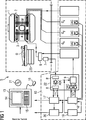
In
In
In
In den Grundfeldmagneten
Innerhalb des Gradientenfeldsystems
Die Umschaltung von Sende- auf Empfangsbetrieb erfolgt über eine Sende-/Empfangsweiche
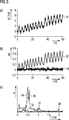
In
Aus den Phasenwerten ΦR,1 und Φn,1 zum Zeitpunkt T1 und den Phasenwerten ΦR,2 und Φn,2 zum Zeitpunkt T2 der Referenzmessung
Über dieselben Phasenwerte und Zeitpunkte (Zeitintervalle) lässt sich gemäß der folgenden Gleichung (2) die Frequenzänderung (Steigungsänderung) Δω zwischen der Frequenz (Steigung der Phase) der Referenzmessung und der Frequenz (Steigung) der eigentlichen Messung bestimmen.
Anhand der Phasendifferenz ΔΦ und der Frequenzänderung Δω kann nun das im K-Raum während der eigentlichen Messung erfasste Signal durch die Multiplikation mit einem von der Zeit t abhängigen Faktor F gemäß der folgenden Gleichung (3) korrigiert werden.
Gemäß einer vereinfachten Korrektur wird nur das Echosignal im K-Raum-Zentrum für die Referenzmessung
Mit der Frequenzänderung Δω kann das K-Raum-Signal durch die Multiplikation mit einem von der Zeit t abhängigen Faktor F gemäß der folgenden Gleichung (5) korrigiert werden.
Die vereinfachte Korrektur setzt voraus, dass die Phasendifferenz ΔΦ während der Messungen (Abtastung des K-Raums) im Wesentlichen konstant bleibt.The simplified correction assumes that the phase difference ΔΦ remains essentially constant during the measurements (scanning of the K-space).
Aus dem mit dem Term gemäß Gleichung (3) oder gemäß Gleichung (5) korrigierten K-Raum-Signal wird nun beispielsweise mittels einer Fouriertransformation pro Voxel des vorbestimmten Volumenabschnitts, welcher mit dem K-Raum, in welchem die K-Raum-Signale erfasst werden, korrespondiert, ein Amplitudenwert und einen Phasenwert bestimmt. Mit anderen Worten wird durch die beiden vorab beschriebenen Korrekturen entsprechend auch eine Phaseninformation, nämlich der Phasenwert pro Voxel des vorbestimmten Volumenabschnitts, korrigiert.The K-space signal corrected with the term according to equation (3) or according to equation (5) is now detected, for example, by means of a Fourier transformation per voxel of the predetermined volume segment, which matches the K-space in which the K-space signals are detected are, corresponds, an amplitude value and a phase value determined. In other words, the two corrections described above also correspondingly correct phase information, namely the phase value per voxel of the predetermined volume segment.
In
Ein Mittelwert der Phasenwerte der Voxel des vorbestimmten Volumenabschnitts über der Zeit ist in
In
In
Im ersten Schritt S1 wird das Grundmagnetfelds B0 angelegt.In the first step S1, the basic magnetic field B0 is applied.
Anschließend wird im folgenden Schritt S2 der K-Raum, welcher mit dem abzutastenden vorbestimmten Volumenabschnitt korrespondiert, mit Hilfe eines Echoplanarverfahrens abgetastet, wobei auch ein Navigatorsignal erfasst wird.Subsequently, in the following step S2, the K-space, which corresponds to the predetermined volume segment to be scanned, is scanned by means of an echo planar method, wherein a navigator signal is also detected.
Anhand der Ergebnisse, welche durch das Navigatorsignal erfasst werden, werden die K-Raum-Messwerte direkt oder die daraus abgeleiteten MR-Daten im Bildraum im Schritt S3 korrigiert.On the basis of the results which are detected by the navigator signal, the K-space measured values are corrected directly or the MR data derived therefrom in the image space in step S3.
Ausgehend von den korrigierten K-Raum-Messwerten oder den korrigierten MR-Daten werden im Schritt S4 die Phasenwerte (und auch Amplitudenwerte) pro Pixel des vorbestimmten Volumenabschnitts berechnet.Based on the corrected K-space measured values or the corrected MR data, the phase values (and also amplitude values) per pixel of the predetermined volume section are calculated in step S4.
Claims (16)
Priority Applications (5)
| Application Number | Priority Date | Filing Date | Title |
|---|---|---|---|
| DE102011006230A DE102011006230B4 (en) | 2011-03-28 | 2011-03-28 | Pixel-wise correction of phase information in MR images using a navigator signal |
| US13/422,271 US9329254B2 (en) | 2011-03-28 | 2012-03-16 | Magnetic resonance method and system to correct phase information in MR images |
| JP2012069388A JP2012205897A (en) | 2011-03-28 | 2012-03-26 | Method for correcting phase information in magnetic resonance image and magnetic resonance equipment |
| KR1020120031067A KR101657331B1 (en) | 2011-03-28 | 2012-03-27 | Method to correct phase information in mr images, and corresponding magnetic resonance system |
| CN201210085167.3A CN102697501B (en) | 2011-03-28 | 2012-03-28 | Correct the method for the phase information in magnetic resonance image (MRI) and corresponding magnetic resonance equipment |
Applications Claiming Priority (1)
| Application Number | Priority Date | Filing Date | Title |
|---|---|---|---|
| DE102011006230A DE102011006230B4 (en) | 2011-03-28 | 2011-03-28 | Pixel-wise correction of phase information in MR images using a navigator signal |
Publications (2)
| Publication Number | Publication Date |
|---|---|
| DE102011006230A1 DE102011006230A1 (en) | 2012-10-04 |
| DE102011006230B4 true DE102011006230B4 (en) | 2013-01-24 |
Family
ID=46844685
Family Applications (1)
| Application Number | Title | Priority Date | Filing Date |
|---|---|---|---|
| DE102011006230A Active DE102011006230B4 (en) | 2011-03-28 | 2011-03-28 | Pixel-wise correction of phase information in MR images using a navigator signal |
Country Status (5)
| Country | Link |
|---|---|
| US (1) | US9329254B2 (en) |
| JP (1) | JP2012205897A (en) |
| KR (1) | KR101657331B1 (en) |
| CN (1) | CN102697501B (en) |
| DE (1) | DE102011006230B4 (en) |
Families Citing this family (32)
| Publication number | Priority date | Publication date | Assignee | Title |
|---|---|---|---|---|
| US9304177B2 (en) * | 2012-03-22 | 2016-04-05 | Tdk Corporation | Movable coil scanner systems and methods |
| DE102012222413B4 (en) | 2012-12-06 | 2023-10-26 | Siemens Healthcare Gmbh | Method for generating an HF excitation pulse for stimulating an arbitrarily shaped volume, method for specifically stimulating spins within a vessel and method for creating MR angiography images and corresponding magnetic resonance system |
| DE102012223789B4 (en) | 2012-12-19 | 2014-07-17 | Siemens Aktiengesellschaft | Determination of a phase difference map |
| KR101593480B1 (en) | 2013-01-04 | 2016-02-15 | 연세대학교 원주산학협력단 | Magnetic Resonance Diffusion Tensor Imaging Registration and Distortion Correction Method and System Using Image Intensity Minimization |
| DE102013201670B3 (en) | 2013-02-01 | 2014-07-03 | Siemens Aktiengesellschaft | Method for acquiring magnetic resonance (MR) data within volume section, involves applying second gradient after high frequency pulse and selecting MR data such that first and second gradients at subsequent sequences are different |
| DE102013209295B4 (en) * | 2013-05-21 | 2016-11-17 | Siemens Healthcare Gmbh | Correction of MR image datasets using a similarity of temporally successive datasets |
| DE102014209364B3 (en) * | 2014-05-16 | 2015-10-08 | Siemens Aktiengesellschaft | Determination of complex sensitivity factors of RF receiver coils |
| US10162037B2 (en) | 2015-09-29 | 2018-12-25 | Siemens Healthcare Gmbh | Navigator-based data correction for simultaneous multislice MR imaging |
| DE102015222835B4 (en) * | 2015-11-19 | 2019-06-13 | Siemens Healthcare Gmbh | Magnetic resonance imaging method with simultaneous image acquisition of several partial volumes with a synchronous image acquisition by navigators |
| DE102015224054B4 (en) * | 2015-12-02 | 2017-11-23 | Julius-Maximilians-Universität Würzburg | Modified TrueFISP sequence for parallel MR data acquisition |
| US10466381B2 (en) * | 2015-12-28 | 2019-11-05 | Baker Hughes, A Ge Company, Llc | NMR logging in formation with micro-porosity by using first echoes from multiple measurements |
| DE102016200603B4 (en) | 2016-01-19 | 2018-02-01 | Siemens Healthcare Gmbh | MULTILAYER GRADIENTENECHO MAGNETIC RESONANCE IMAGING |
| DE102016217223A1 (en) * | 2016-09-09 | 2018-03-15 | Siemens Healthcare Gmbh | Verification of a temporal change of a magnetic field in a magnetic resonance device |
| CN106443533B (en) * | 2016-09-21 | 2019-08-09 | 清华大学 | Based on the navigation magnetic resonance diffusion imaging method repeatedly excited and device |
| CN107037386B (en) * | 2016-11-01 | 2019-08-23 | 上海联影医疗科技有限公司 | A kind of echo planar imaging and system |
| EP3388855A1 (en) * | 2017-04-12 | 2018-10-17 | Siemens Healthcare GmbH | Device and method for the recovery of time-related references in free running mr reception chains |
| CN109901088B (en) * | 2017-12-11 | 2023-08-22 | 通用电气公司 | Motion tracking method, computer program and storage device for magnetic resonance imaging |
| CN110353681B (en) * | 2018-03-26 | 2023-09-01 | 西门子医疗有限公司 | Method and device for correcting B0 inhomogeneity by means of high-frequency signals |
| EP3627172B1 (en) | 2018-09-18 | 2022-02-09 | Siemens Healthcare GmbH | Method and apparatus for simultaneous multi-slice magnetic resonance imaging |
| DE102018216774A1 (en) | 2018-09-28 | 2020-04-02 | Siemens Healthcare Gmbh | Correction procedure for layer multiplexing EPI procedures |
| CN109521383B (en) * | 2018-10-17 | 2019-08-30 | 浙江大学 | A kind of magnetic resonance CEST imaging sequence and device based on frequency stabilization module |
| WO2020084626A1 (en) * | 2018-10-26 | 2020-04-30 | Aspect Imaging Ltd. | Systems and methods for mri motion correction during mri image acquisition |
| US11163029B2 (en) * | 2019-08-14 | 2021-11-02 | GE Precision Healthcare LLC | MRI system with improved navigator |
| CN110473271B (en) * | 2019-08-20 | 2022-12-06 | 上海联影医疗科技股份有限公司 | Image data processing method, system, device and storage medium |
| WO2021133961A1 (en) * | 2019-12-26 | 2021-07-01 | The Brigham And Women's Hospital, Inc. | System and method for controlling physiological noise in functional magnetic resonance imaging |
| CN113625209B (en) * | 2020-05-09 | 2024-02-27 | 上海联影医疗科技股份有限公司 | Method and device for determining frequency drift amount of magnetic resonance system and computer equipment |
| DE102020209382A1 (en) * | 2020-07-24 | 2022-01-27 | Siemens Healthcare Gmbh | Method for recording measurement data using a magnetic resonance system with a correction of the k-space trajectories used |
| DE102020209911A1 (en) | 2020-08-05 | 2022-02-10 | Siemens Healthcare Gmbh | Correction of influences on a magnetic resonance tomography of an examination subject caused by fluctuations in a basic magnetic field |
| WO2023034044A1 (en) * | 2021-08-30 | 2023-03-09 | Children's Medical Center Corporation | Dynamic distortion correction for mri using fid navigators |
| DE102022202094A1 (en) | 2022-03-01 | 2023-09-07 | Siemens Healthcare Gmbh | Image reconstruction from magnetic resonance measurement data with a trained function |
| DE102022207891A1 (en) | 2022-07-29 | 2024-02-01 | Siemens Healthcare Gmbh | Method for slice-specific correction of measurement data recorded simultaneously for at least two slices using an echo-planar simultaneous multi-slice technique |
| DE102022207892B4 (en) | 2022-07-29 | 2024-03-07 | Siemens Healthcare Gmbh | Method for slice-specific correction of measurement data recorded simultaneously for at least two slices using an echo-planar simultaneous multi-slice technique |
Citations (3)
| Publication number | Priority date | Publication date | Assignee | Title |
|---|---|---|---|---|
| DE10114318A1 (en) * | 2000-03-31 | 2001-10-04 | Ge Med Sys Global Tech Co Llc | Method for characterization of magnet system instabilities in a nuclear magnetic resonance tomography system so that patient images can be improved enabling a better diagnosis to be made |
| US6853191B1 (en) * | 2003-12-10 | 2005-02-08 | The Board Of Trustees Of The Leland Stanford Junior University | Method of removing dynamic nonlinear phase errors from MRI data |
| DE10330926A1 (en) * | 2003-07-08 | 2005-02-17 | Siemens Ag | Method for the absolute correction of B0 field deviations in magnetic resonance tomography imaging |
Family Cites Families (8)
| Publication number | Priority date | Publication date | Assignee | Title |
|---|---|---|---|---|
| JP3815585B2 (en) * | 1997-10-17 | 2006-08-30 | 株式会社日立メディコ | Magnetic resonance imaging system |
| JP3878429B2 (en) * | 2001-04-05 | 2007-02-07 | ジーイー・メディカル・システムズ・グローバル・テクノロジー・カンパニー・エルエルシー | MRI equipment |
| DE10117752C1 (en) * | 2001-04-09 | 2003-02-27 | Siemens Ag | Magnetic resonance imaging device with a device for movement correction |
| JP4141147B2 (en) | 2002-02-01 | 2008-08-27 | 株式会社日立メディコ | Magnetic resonance imaging system |
| US7408345B2 (en) * | 2006-02-06 | 2008-08-05 | The Board Of Trustees Of The Leland Stanford Junior University | Generalized MRI reconstruction with correction for multiple image distortion |
| US8406849B2 (en) * | 2006-03-31 | 2013-03-26 | University Of Utah Research Foundation | Systems and methods for magnetic resonance imaging |
| US8483457B2 (en) * | 2010-07-07 | 2013-07-09 | General Electric Company | System and method of image artifact reduction using self-navigated real-time phase correction in echo planar imaging |
| JP5835989B2 (en) * | 2010-08-11 | 2015-12-24 | 株式会社東芝 | Magnetic resonance imaging apparatus and magnetic resonance imaging method |
-
2011
- 2011-03-28 DE DE102011006230A patent/DE102011006230B4/en active Active
-
2012
- 2012-03-16 US US13/422,271 patent/US9329254B2/en active Active
- 2012-03-26 JP JP2012069388A patent/JP2012205897A/en active Pending
- 2012-03-27 KR KR1020120031067A patent/KR101657331B1/en active IP Right Grant
- 2012-03-28 CN CN201210085167.3A patent/CN102697501B/en active Active
Patent Citations (3)
| Publication number | Priority date | Publication date | Assignee | Title |
|---|---|---|---|---|
| DE10114318A1 (en) * | 2000-03-31 | 2001-10-04 | Ge Med Sys Global Tech Co Llc | Method for characterization of magnet system instabilities in a nuclear magnetic resonance tomography system so that patient images can be improved enabling a better diagnosis to be made |
| DE10330926A1 (en) * | 2003-07-08 | 2005-02-17 | Siemens Ag | Method for the absolute correction of B0 field deviations in magnetic resonance tomography imaging |
| US6853191B1 (en) * | 2003-12-10 | 2005-02-08 | The Board Of Trustees Of The Leland Stanford Junior University | Method of removing dynamic nonlinear phase errors from MRI data |
Non-Patent Citations (2)
| Title |
|---|
| C. Liu et al.: Simultaneous phase correction and SENSE reconstruction for navigated multi-shot DWI with non-cartesian k-space sampling. In: Magn. Reson. Med., 54, 2005, S. 1412-1422. * |
| D.H.J. Poot et al.: Improved B0 field map estimation for high field EPI. In: Magn. Reson. Imag., 28, 2010, S. 441-450. * |
Also Published As
| Publication number | Publication date |
|---|---|
| US9329254B2 (en) | 2016-05-03 |
| US20120249138A1 (en) | 2012-10-04 |
| KR20120110056A (en) | 2012-10-09 |
| DE102011006230A1 (en) | 2012-10-04 |
| KR101657331B1 (en) | 2016-09-13 |
| CN102697501B (en) | 2015-10-28 |
| JP2012205897A (en) | 2012-10-25 |
| CN102697501A (en) | 2012-10-03 |
Similar Documents
| Publication | Publication Date | Title |
|---|---|---|
| DE102011006230B4 (en) | Pixel-wise correction of phase information in MR images using a navigator signal | |
| DE102011077197B4 (en) | Distortion correction in magnetic resonance imaging | |
| DE102013215703B3 (en) | Determination of a T1 time of water and a T1 time of fat | |
| DE19821780B4 (en) | Correction of artifacts caused by Maxwell terms in cut-shift echo-planar imaging | |
| DE102011083898B4 (en) | Acquiring magnetic resonance data at the edge of the field of view of a magnetic resonance system | |
| DE102010032080B4 (en) | Triggered Magnetic Resonance Imaging Based on Partial Parallel Acquisition (PPA) | |
| DE102011083395B4 (en) | Correction of distortions in MR images due to inhomogeneities of the basic magnetic field | |
| DE10330926B4 (en) | Method for the absolute correction of B0 field deviations in magnetic resonance tomography imaging | |
| DE102015221888B4 (en) | Simultaneous MRI multilayer measurement | |
| DE102016200603B4 (en) | MULTILAYER GRADIENTENECHO MAGNETIC RESONANCE IMAGING | |
| DE102011085033B4 (en) | Correction of artifacts in MR images due to insufficient excitation at ultrashort echo times | |
| DE102014205004B3 (en) | Method and magnetic resonance system for acquiring MR data of a slice of a volume segment within an examination subject | |
| DE102014219320B4 (en) | Reconstruction of an MR image taking into account the chemical shift | |
| DE102015205693A1 (en) | Speed-compensated diffusion-sensitized diffusion imaging | |
| DE102011083871B4 (en) | Adaptation of the fundamental frequency of an RF excitation pulse during the non-selective excitation of nuclear spin signals in an examination subject | |
| DE102016207641A1 (en) | Parallel Magnetic Resonance Acquisition Technique | |
| EP3176596B1 (en) | Modified truefisp sequence for parallel mr data acquisition | |
| DE102016200889B4 (en) | Reconstruction of image data | |
| EP3441781A1 (en) | Accelerated magnetic resonance measurement | |
| DE102013207438A1 (en) | Method for generating image data records of an examination subject by means of a magnetic resonance apparatus | |
| DE102014204995B4 (en) | Method and magnetic resonance system for fat saturation | |
| DE102012210324B4 (en) | Adjustment of the echo train length in the acquisition of MR data in a predetermined volume section | |
| DE10256209B4 (en) | A method of automatically determining the actual velocity interval of a flowing medium in flow measurements in magnetic resonance tomography, and magnetic resonance imaging apparatus and computer software product | |
| DE10256208B4 (en) | Method for improved flow measurement in magnetic resonance tomography | |
| DE102015207352B4 (en) | Quantitative T1 determination in MR imaging |
Legal Events
| Date | Code | Title | Description |
|---|---|---|---|
| R012 | Request for examination validly filed | ||
| R016 | Response to examination communication | ||
| R018 | Grant decision by examination section/examining division | ||
| R020 | Patent grant now final |
Effective date: 20130425 |
|
| R081 | Change of applicant/patentee |
Owner name: SIEMENS HEALTHCARE GMBH, DE Free format text: FORMER OWNER: SIEMENS AKTIENGESELLSCHAFT, 80333 MUENCHEN, DE |
|
| R081 | Change of applicant/patentee |
Owner name: SIEMENS HEALTHINEERS AG, DE Free format text: FORMER OWNER: SIEMENS HEALTHCARE GMBH, MUENCHEN, DE |