EP0909595A2 - Filière d'étirage de fil - Google Patents
Filière d'étirage de fil Download PDFInfo
- Publication number
- EP0909595A2 EP0909595A2 EP98308252A EP98308252A EP0909595A2 EP 0909595 A2 EP0909595 A2 EP 0909595A2 EP 98308252 A EP98308252 A EP 98308252A EP 98308252 A EP98308252 A EP 98308252A EP 0909595 A2 EP0909595 A2 EP 0909595A2
- Authority
- EP
- European Patent Office
- Prior art keywords
- wire drawing
- longitudinal axis
- zone
- compact
- entrance
- Prior art date
- Legal status (The legal status is an assumption and is not a legal conclusion. Google has not performed a legal analysis and makes no representation as to the accuracy of the status listed.)
- Granted
Links
Images
Classifications
-
- B—PERFORMING OPERATIONS; TRANSPORTING
- B21—MECHANICAL METAL-WORKING WITHOUT ESSENTIALLY REMOVING MATERIAL; PUNCHING METAL
- B21C—MANUFACTURE OF METAL SHEETS, WIRE, RODS, TUBES, PROFILES OR LIKE SEMI-MANUFACTURED PRODUCTS OTHERWISE THAN BY ROLLING; AUXILIARY OPERATIONS USED IN CONNECTION WITH METAL-WORKING WITHOUT ESSENTIALLY REMOVING MATERIAL
- B21C3/00—Profiling tools for metal drawing; Combinations of dies and mandrels for metal drawing
- B21C3/02—Dies; Selection of material therefor; Cleaning thereof
- B21C3/04—Dies; Selection of material therefor; Cleaning thereof with non-adjustable section
-
- B—PERFORMING OPERATIONS; TRANSPORTING
- B21—MECHANICAL METAL-WORKING WITHOUT ESSENTIALLY REMOVING MATERIAL; PUNCHING METAL
- B21C—MANUFACTURE OF METAL SHEETS, WIRE, RODS, TUBES, PROFILES OR LIKE SEMI-MANUFACTURED PRODUCTS OTHERWISE THAN BY ROLLING; AUXILIARY OPERATIONS USED IN CONNECTION WITH METAL-WORKING WITHOUT ESSENTIALLY REMOVING MATERIAL
- B21C3/00—Profiling tools for metal drawing; Combinations of dies and mandrels for metal drawing
- B21C3/02—Dies; Selection of material therefor; Cleaning thereof
- B21C3/025—Dies; Selection of material therefor; Cleaning thereof comprising diamond parts
Definitions
- the present invention relates to wire drawing dies, and more particularly to dies formed of a cemented metal carbide supported, polycrystalline diamond (PCD) or polycrystalline cubic boron nitride (PCBN) compact wherein a non-cylindrical interface is provided between the compact and the support layers for improved physical properties.
- PCD polycrystalline diamond
- PCBN polycrystalline cubic boron nitride
- a compact may be characterized generally as an integrally-bonded structure formed of a sintered, polycrystalline mass of abrasive particles, such as diamond or CBN.
- abrasive particles such as diamond or CBN.
- Such compacts may be self-bonded without the aid of a bonding matrix or second phase, it generally is preferred, as is discussed in U.S. Patents Nos. 4,063,909 and 4,60,423, to employ a suitable bonding matrix which usually is a metal such as cobalt, iron, nickel, platinum, titanium, chromium, tantalum, copper, or an alloy or mixture thereof.
- the bonding matrix which is provided at from about 5% to 35% by volume, additionally may contain recrystallization or growth catalyst such as aluminum for CBN or cobalt for diamond.
- the compact is supported by its bonding to substrate material to form a laminate or supported compact arrangement.
- the substrate material is provided as a cemented metal carbide which comprises, for example, tungsten, titanium, or tantalum carbide particles, or a mixture thereof, which are bonded together with a binder of between about 6% to about 25% by weight of a metal such as cobalt, nickel, or iron, or a mixture or alloy thereof.
- a metal such as cobalt, nickel, or iron, or a mixture or alloy thereof.
- the basic HP/HT method for manufacturing the polycrystalline compacts and supported compacts of the type herein involved entails the placing of an unsintered mass of abrasive, crystalline particles, such as diamond or CBN, or a mixture thereof, within a protectively shielded metal enclosure which is disposed within the reaction cell of an HT/HP apparatus of a type described further in U.S. Patents Nos. 2,947,611; 2,941,241; 2,941,248; 3,609,818; 3,767,371; 4,289,503; 4,673,414; and 4,954,139.
- abrasive particles may be a metal catalyst if the sintering of diamond particles is contemplated, as well as a pre-formed mass of a cemented metal carbide for supporting the abrasive particles and to thereby form a supported compact therewith.
- the contents of the cell then are subjected to processing conditions selected as sufficient to effect intercrystalline bonding between adjacent grains of abrasive particles and, optionally, the joining of sintered particles to the cemented metal carbide support.
- processing conditions generally involve the imposition for about 3 to 120 minutes of a temperature of at least 1300° C and a pressure of at least 20 kbar.
- the catalyst metal may be provided in a pre-consolidated form disposed adjacent the crystal particles.
- the metal catalyst may be configured as an annulus into which is received a cylinder of abrasive crystal particles, or as a disc which is disposed above or below the crystalline mass.
- the metal catalyst, or solvent as it is also known may be provided in a powdered form and intermixed with the abrasive crystalline particles, or as a cemented metal carbide or carbide molding powder which may be cold pressed into shape and wherein the cementing agent is provided as a catalyst or solvent for diamond recrystallization or growth.
- the metal catalyst is selected from cobalt, iron, or nickel, or an alloy or mixture thereof, but other metals such as ruthenium, rhodium, palladium, chromium, manganese, tantalum, copper, and alloys and mixtures thereof also may be employed.
- the metal catalyst in whatever form provided, is caused to penetrate or "sweep: into the abrasive layer by means of either diffusion or capillary action, and is thereby made available as a catalyst or solvent for recrystallization or crystal intergrowth.
- the HT/HP conditions which operate in the diamond stable thermodynamic region above the equilibrium between diamond and graphite phases, effect a compaction of the abrasive crystal particles which is characterized by intercrystalline diamond-to-diamond bonding wherein parts of each crystalline lattice are shared are shared between adjacent crystal grains.
- the diamond concentration in the compact or in the abrasive table of the supported compact is at least about 70% by volume.
- CBN compacts and supported compacts are manufactured in general accordance with the methods suitable for diamond compacts.
- the metal which is swept through the crystalline mass need not necessarily be a catalyst or solvent for CBN recrystallization.
- a polycrystalline mass of CBN may be joined to the cobalt-cemented tungsten carbide substrate by the sweep through of the cobalt from the substrate and into the interstices of the crystalline mass notwithstanding that cobalt is not a catalyst or solvent for the recrystallization of CBN. Rather, the interstitial cobalt functions as a binder between the polycrystalline CBN compact and the cemented tungsten carbide substrate.
- the HT/HP sintering process for CBN is effected under conditions in which CBN is the thermodynamically stable phase. It is speculated that under these conditions, intercrystalline bonding between adjacent crystal grains also is effected.
- the CBN concentration in the compact or in the abrasive table of the supported compact is preferably at least about 50% by volume.
- Methods for making CBN compacts and supported compacts are more fully described in U.S. Patents Nos. 2,947,617; 3,136,615; 3,233,988; 3,743,489; 3,745,623; 3,831,428; 3,928,219; 4,188,194; 4,289,503; 4,673,414; 4,797,326; and 4,954,139.
- Exemplary CBN compacts are disclosed in U.S. Patent No. 3,767,371 to contain greater than about 70% by volume of CBN and less than about 30% by volume of a binder metal such as cobalt.
- yet another form of a polycrystalline compact which form need not necessarily exhibit direct or intercrystalline bonding, involves a polycrystalline mass of diamond or CBN particles having a second phase of a metal or alloy, a ceramic, or a mixture thereof.
- the second material phase is seen to function as a bonding agent for abrasive crystal particles.
- Polycrystalline diamond and polycrystalline CBN compacts containing a second phase of a cemented carbide are exemplary of the conjoint" polycrystalline abrasive compacts.
- Such compacts may be considered to be "thermally-stable as compared to metal-containing compacts as having service temperatures above about 700° C.
- Compacts as those described in U.S. Patent No. 4,334,928 to comprise 80 to 10% by volume of CBN and 20 to 90% by volume of a nitride binder such as titanium nitride also may be considered exemplary of a thermally-stable material.
- HT/HP sintering processes as are described in U.S. Pats. Nos. 3,831,428 and 4,534,934 may be considered preferred.
- the preferred HT/HP processes entail the sweep of a catalytic or binder metal, such as cobalt, through a mass of CBN or PCD particles.
- the particles are charged within a support of a surrounding metal carbide annulus.
- metal from the support and, optionally, from an axially disposed disc is made to infiltrate radially and/or axially into the interstices of the crystalline mass.
- the infiltrated metal forms a separate binder phase and, at least with respect to PCD, effects significant intercrystalline bonding.
- the metal additionally joins the sintered compact to the support to form an integral structure.
- the wire drawing hole may be formed through the sintered compact as a finishing step by laser drilling or other machining techniques. Alternatively, the hole may be pre-formed by including a wire as axially disposed within the particle mass, which wire is removed after the sintering of the mass by dissolution in a suitable acid or other solvent or by machining techniques.
- the product or blank which is recovered from the reaction cell of the HT/HP apparatus is subjected to a variety of finishing operations which include cutting, such as by electrode discharge machining or with lasers, milling, and especially grinding to remove any adherent shield metal from the outer surfaces of the compact.
- finishing operations additionally are employed to machine the compact into a cylindrical shape or the like which meets product specifications as to diamond or CBN abrasive table thickness and/or carbide support thickness.
- the die With respect to wire drawing dies in particular, prior to use, the die generally is brazed into a receiving ring or other support assembly.
- the temperature of the blank which previously has been exposed to a thermal cycle during its HT/HP processing and cooling to room temperature, can be elevated due to the thermal effects of the operations.
- the carbide support owing to its relatively higher coefficient of thermal expansion (CTE)
- CTE coefficient of thermal expansion
- the stresses generated are relieved principally through the deformation of the compact layer which may result in its stress cracking and delamination from its support.
- U.S. Patent No. 4,374,900 suggests surrounding the circumference of the diamond compact with a cermet material which contains molybdenum as a predominant component.
- the cermet is stated to have a high degree of plastic deformation and a high rigidity at elevated temperatures.
- U.S. Patent No. 5,033,334 discloses a wire drawing die wherein the outer surface of the compact is metallized and then brazed to the mating surface of the support. Such die is stated to have an improved bond strength as between the compact and support components.
- PCD commonly is used as a die material in drawing metal wire such as, for example, copper and its alloys, various steels, and other precious metals.
- metal wire such as, for example, copper and its alloys, various steels, and other precious metals.
- a common failure mode is the formation of a wear ring in the entrance or reduction region of the die where the wire first contacts the diamond material. During use, this wear ring moves down the axis of the die until it eventually causes breakage of the wire, imparts unfavorable residual stresses in the wire, or results in an out-of-shape product.
- the wear ring presumably forms by successive pitting of the PCD or other material surface which typically is under tensile stresses. If these tensile stresses can be reduced or changed to compressive stresses, the rate of wear ring formation should be slowed during operation.
- the present invention is based on the discovery that by making the carbide annulus/polycrystalline component interface surface extend inwardly from the entrance end of the die to the vicinity of the wear ring location, that stresses in the compact can be materially diminished which should lead to longer service life. Moreover, the interface configuration for the remaining die down to the exit end is much less important and can, for example, remain in a conventional cylindrical configuration. While the performance of the present wire drawing die may not reach that of the wire drawing die disclosed in '075 patent, its expected lower production costs and ease of manufacture should make it an attractive alternative product which is much improved over conventional cylindrical interface wire drawing die products.
- the present invention is addressed to improving a blank for converting into a wire drawing die which is formed from an annular cemented metal carbide support component having a lengthwise extent from an entrance end to an exit end and extending radially about a central longitudinal axis to define a cylindrical internal bore through the lengthwise extent, and a cylindrical sintered polycrystalline compact component received within the bore of the support component and bonded thereto at an interface surface extending a radial distance from and along the longitudinal axis from a wire drawing entrance end to a wire drawing exit end.
- the compact component is adapted to receive an aperture extending through its lengthwise extent about the central longitudinal axis and is configured with an entrance zone at the die entrance end which tapers inwardly therefrom to a reduction zone whereat a wire to be drawn through the aperture makes initial contact with the compact component, and thence to a bearing zone and an exit zone.
- the improvement in such wire drawing die blank revolves around the radial distance from said central longitudinal axis to said interface surface tapers inwardly from the entrance end to a minimum prior to the bearing zone after which said radial distance remains substantially constant to said exit end.
- Another aspect of the present invention is addressed to improving a wire drawing die formed from an annular cemented metal carbide support component having a lengthwise extent from an entrance end to an exit end and extending radially about a central longitudinal axis to define a cylindrical internal bore through the lengthwise extent, and a cylindrical sintered polycrystalline compact component received within the bore of the support component and bonded thereto at an interface surface extending a radial distance from and along the longitudinal axis from a wire drawing entrance end to a wire drawing exit end.
- the compact component has an aperture extending through its lengthwise extent about the central longitudinal axis and is configured with an entrance zone at the die entrance end which tapers inwardly therefrom to a reduction zone whereat a wire to be drawn through the aperture makes initial contact with the compact component, and thence to a bearing zone and an exit zone.
- the improvement in such wire drawing die revolves around the radial distance from said central longitudinal axis to said interface surface tapers inwardly from the entrance end to a minimum prior to the bearing zone after which said radial distance remains substantially constant to said exit end.
- a process for forming a wire drawing die blank formed by a high pressure/high temperature (HP/HT) process commences by providing a reaction cell assembly which includes an annular cemented metal carbide support component having a lengthwise extent from an entrance end to an exit end and extending radially about a central longitudinal axis to define a cylindrical internal bore through the lengthwise extent.
- the reaction cell assembly also includes a sinterable mass of crystalline particles received within the bore of the support component.
- the process continues by subjecting the reaction cell assembly to HP/HT conditions selected as being effective to sinter the mass of crystalline particles into a polycrystalline compact which compact is adapted to have an aperture extending through its lengthwise extent about the central longitudinal axis and configured with an entrance zone at the entrance end which tapers inwardly therefrom to a reduction zone whereat a wire to be drawn through the aperture makes initial contact with said compact component, and thence to a bearing zone and an exit zone.
- HP/HT conditions selected as being effective to sinter the mass of crystalline particles into a polycrystalline compact which compact is adapted to have an aperture extending through its lengthwise extent about the central longitudinal axis and configured with an entrance zone at the entrance end which tapers inwardly therefrom to a reduction zone whereat a wire to be drawn through the aperture makes initial contact with said compact component, and thence to a bearing zone and an exit zone.
- the HP/HT conditions also are selected as being effective to bond the compact to the support component at an interface surface extending along the longitudinal axis wherein the radial distance from said central longitudinal axis to said interface surface tapers inwardly from the entrance end to a minimum prior to the bearing zone after which said radial distance remains substantially constant to said exit end.
- Advantages of the present invention include the provision of a wire drawing die and blank therefor which have residual stresses which are controlled to promote an extended service life, and reduced susceptibility to failure. Another advantage is a wire drawing die and blank therefor having improved machinability, performance, and wear properties.
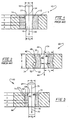
- a wire drawing die substantially in accordance with the prior an is shown at 10 to include inner, polycrystalline compact component 12, bonded at interface or bondline 14, to cemented metal carbide support layer 16.
- a wire drawing aperture or throat, represented at 18, is provided in to extend through compact component 12 for receiving the wire being drawn.
- wire feedstock 19 of a given diameter, d 1 is drawn through aperture 18 in the direction shown by arrow 20 for elongation into a wire product of reduced diameter, d 2 .
- Drawing aperture 18 preferably is configured as being tapered either doubly or piecewise to define a characteristic surface of revolution about central longitudinal axis 24 for confronting wire 19 being drawn.
- Area or region 22 at which wire 19 initially contacts compact component 12 is the wear ring described above.
- wear ring 22 moves down axis 24 of die 10 until it eventually causes breakage of wire 19, imparts unfavorable residual stresses in wire 19, or results in an out-of-shape product.
- wear ring 22 presumably forms by successive pitting of the surface of compact component 12 which typically is under local tensile stresses. If these tensile stresses can be reduced or changed to compressive stresses, the rate of wear ring formation should be slowed during operation.
- the an generally recognizes four distinct zones for wire drawing die 10; entrance zone 1, reduction zone 2, bearing zone 3, and exit zone 4.
- a prior an wire drawing die substantially in accordance with the '075 patent is shown at 30 to include inner sintered polycrystalline compact component 32 and outer support component 34.
- Support component 34 is configured as having a lengthwise extent, I , and as extending about central longitudinal axis 36 to define internal bore 38 therethrough.
- Compact component 32 is received within bore 38 of support componcnt 34 and is bonded thereto at interface surface 40.
- a wire drawing aperture or throat, represented at 42, defining a generally tapered surface of revolution 44 about axis 36, is provided through compact component 32 for receiving a wire (not shown) drawn therethrough in the direction shown at arrow 46 substantially in the same manner as described in connection with Fig. 1.
- interface 40 now extends along axis 36 from entrance end 48, spaced a first local maximum radial distance, r 1 , from axis 36, to exit end 50, spaced a second local maximum radial distance, r 2 , from axis 46.
- Intermediate region 52 is shown spaced a local minimum radial distance, r 3 , from axis 36.
- inventive wire drawing die 60 is seen to include inner polycrystalline compact 62 bonded at interface or bondline 63, to cemented metal carbide support layer 66.
- wire feedstock 69 of a given diameter, d 1 is drawn through aperture 68 in the direction shown by arrow 70 for elongation into a wire product of reduced diameter, d 2 .
- Drawing aperture 68 preferably is configured as being tapered either doubly or piecewise to define a characteristic surface of revolution about central longitudinal axis 75 for confronting wire 69 being drawn.
- Area or region 72 at which wire 69 initially contacts compact component 72 is the wear ring described above.
- the local stresses exerted by wire 69 at wear ring 72 can be accommodated by configuring interface 74 to taper from entrance end 76 where the radial distance from longitudinal centerline 75 to interface 74 is a distance, r e , to wear ring 72 where the radial distance from longitudinal centerline 75 to interface 74 is a distance, r wt , where r e > r wt .
- the taper for interface 74 should be ahead of bearing zone 3, i.e. , in entrance zone 1 or reduction zone 2. It will be observed that interface 74 from wear ring 72 to exit end 78 (bearing zone 3 and exit zone 4) retains the substantially cylindrical configuration of interface 74 of prior an compact 10 in Fig. 1.
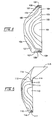
- Figs. 4 and 5 wherein a somewhat stylized representation of a finite element model of the maximum principle stress distributions in a section of a wire drawing die compact are shown for the generally cylindrical interface of compact 10, Fig. 4, and for the novel singly entrance zone taper of compact 60, Fig. 5.
- Each of the sections are shown as having a maximum principle stress distribution graphically depicted by the contours designated 101-109 in Fig. 4 and 110-117 in Fig. 5.
- local stresses 101-105 represent compression stresses
- local stresses 106-109 represent tension stresses, with the local stresses generally increasing in tension as the numeric designations increase.
- local stresses 110-114 represent compressive stresses, while local stresses 115-117 represent tension stresses.
- the local tensile stresses have been reduced. This is expected to minimize wear ring formation.
- the local force distribution patterns are about the same in Figs. 4 and 5; however, wire drawing failures in these zones are not as common.
- the present invention addresses a dominant failure mode for wire drawing dies to configuring the interface to substantially reduce, if not eliminate, wear ring formation, while concomitantly not increasing costs of production of the wire die unnecessarily.
Landscapes
- Engineering & Computer Science (AREA)
- Mechanical Engineering (AREA)
- Metal Extraction Processes (AREA)
Applications Claiming Priority (2)
| Application Number | Priority Date | Filing Date | Title |
|---|---|---|---|
| US950004 | 1978-10-06 | ||
| US08/950,004 US5957005A (en) | 1997-10-14 | 1997-10-14 | Wire drawing die with non-cylindrical interface configuration for reducing stresses |
Publications (3)
| Publication Number | Publication Date |
|---|---|
| EP0909595A2 true EP0909595A2 (fr) | 1999-04-21 |
| EP0909595A3 EP0909595A3 (fr) | 2000-01-05 |
| EP0909595B1 EP0909595B1 (fr) | 2003-02-26 |
Family
ID=25489822
Family Applications (1)
| Application Number | Title | Priority Date | Filing Date |
|---|---|---|---|
| EP98308252A Expired - Lifetime EP0909595B1 (fr) | 1997-10-14 | 1998-10-09 | Filière d'étirage de fil |
Country Status (6)
| Country | Link |
|---|---|
| US (2) | US5957005A (fr) |
| EP (1) | EP0909595B1 (fr) |
| JP (1) | JPH11314112A (fr) |
| KR (1) | KR19990037058A (fr) |
| DE (1) | DE69811594T2 (fr) |
| ZA (1) | ZA988890B (fr) |
Cited By (3)
| Publication number | Priority date | Publication date | Assignee | Title |
|---|---|---|---|---|
| WO2003101638A1 (fr) * | 2002-05-31 | 2003-12-11 | Sumitomo Electric Industries,Ltd. | Materiaux pour filiere pour corps a diamants frittes et filiere pour corps a diamants frittes |
| CN102847739A (zh) * | 2012-09-12 | 2013-01-02 | 苏州晨新轮胎有限公司 | 一种拉丝模具 |
| CN117696661A (zh) * | 2023-12-20 | 2024-03-15 | 浙江嘉杭机械科技有限公司 | 一种小尺寸复杂异型型腔聚晶拉拔模具的制备方法 |
Families Citing this family (18)
| Publication number | Priority date | Publication date | Assignee | Title |
|---|---|---|---|---|
| US5957005A (en) * | 1997-10-14 | 1999-09-28 | General Electric Company | Wire drawing die with non-cylindrical interface configuration for reducing stresses |
| US6304590B1 (en) * | 2000-07-11 | 2001-10-16 | Consarc Corporation | Formation of metal wire |
| WO2005058519A1 (fr) * | 2003-12-10 | 2005-06-30 | Diamond Innovations, Inc. | Filiere a etirer pour diamant |
| US7540181B1 (en) | 2006-10-13 | 2009-06-02 | Us Synthetic Corporation | Wire-drawing die assembly |
| US8002859B2 (en) | 2007-02-06 | 2011-08-23 | Smith International, Inc. | Manufacture of thermally stable cutting elements |
| US7942219B2 (en) | 2007-03-21 | 2011-05-17 | Smith International, Inc. | Polycrystalline diamond constructions having improved thermal stability |
| US9297211B2 (en) | 2007-12-17 | 2016-03-29 | Smith International, Inc. | Polycrystalline diamond construction with controlled gradient metal content |
| GB2473995B (en) * | 2008-07-17 | 2013-01-09 | Smith International | Methods of forming polycrystalline diamond cutters |
| US8702412B2 (en) | 2011-01-12 | 2014-04-22 | Us Synthetic Corporation | Superhard components for injection molds |
| US8512023B2 (en) | 2011-01-12 | 2013-08-20 | Us Synthetic Corporation | Injection mold assembly including an injection mold cavity at least partially defined by a polycrystalline diamond material |
| CN104001746B (zh) * | 2014-06-17 | 2016-08-17 | 安徽振兴拉丝模有限公司 | 一种钛合金镀锡拉丝模及其制备方法 |
| CN104438401A (zh) * | 2014-12-17 | 2015-03-25 | 中利科技集团(辽宁)有限公司 | 一种异型拉丝模具 |
| JP6800160B2 (ja) * | 2015-10-30 | 2020-12-16 | 住友電気工業株式会社 | 伸線ダイス |
| ES2938188T3 (es) * | 2016-12-26 | 2023-04-05 | Almt Corp | Matriz de diamante con forma atípica |
| KR102108082B1 (ko) | 2018-11-22 | 2020-05-07 | (주)우신스틸 | 다단형 인발다이 |
| CN111545587A (zh) * | 2020-05-14 | 2020-08-18 | 南京雄豹精密机械有限公司 | 折弯机下模的加工方法 |
| KR102373109B1 (ko) * | 2021-02-25 | 2022-03-11 | (주)고려기업 | 고광택 스테인리스 와이어 제조방법 및 그 제조장치 |
| CN112893496A (zh) * | 2021-03-19 | 2021-06-04 | 常州工业职业技术学院 | 金属纤维控温拉丝细化装置 |
Family Cites Families (51)
| Publication number | Priority date | Publication date | Assignee | Title |
|---|---|---|---|---|
| US354991A (en) * | 1886-12-28 | Wire-drawing device | ||
| US1395217A (en) * | 1920-12-18 | 1921-10-25 | Begot Louis Hippolyte Edmond | Cascade extrusion-die for cold or hot spinning of metals |
| US2941241A (en) * | 1955-02-14 | 1960-06-21 | Gen Electric | High temperature high pressure apparatus |
| US2947611A (en) * | 1958-01-06 | 1960-08-02 | Gen Electric | Diamond synthesis |
| US2941248A (en) * | 1958-01-06 | 1960-06-21 | Gen Electric | High temperature high pressure apparatus |
| US3136615A (en) * | 1960-10-03 | 1964-06-09 | Gen Electric | Compact of abrasive crystalline material with boron carbide bonding medium |
| US3142746A (en) * | 1961-07-28 | 1964-07-28 | Smith Corp A O | Consumable electrode arc welding apparatus |
| US3233988A (en) * | 1964-05-19 | 1966-02-08 | Gen Electric | Cubic boron nitride compact and method for its production |
| DE1452389A1 (de) * | 1965-08-02 | 1968-11-28 | Mannesmann Ag | Matrize zum Strangpressen von Metallen |
| US3381428A (en) * | 1967-08-22 | 1968-05-07 | Unitized Mfg Ltd | Exposed lock log joining system |
| US3609818A (en) * | 1970-01-02 | 1971-10-05 | Gen Electric | Reaction vessel for high pressure apparatus |
| US3850591A (en) * | 1970-01-02 | 1974-11-26 | Gen Electric | Process for preparation of high pressure apparatus reaction vessel construction |
| US3831428A (en) * | 1973-03-26 | 1974-08-27 | Gen Electric | Composite wire drawing die |
| US3852078A (en) * | 1970-12-24 | 1974-12-03 | M Wakatsuki | Mass of polycrystalline cubic system boron nitride and composites of polycrystalline cubic system boron nitride and other hard materials, and processes for manufacturing the same |
| US3743489A (en) * | 1971-07-01 | 1973-07-03 | Gen Electric | Abrasive bodies of finely-divided cubic boron nitride crystals |
| US3767371A (en) * | 1971-07-01 | 1973-10-23 | Gen Electric | Cubic boron nitride/sintered carbide abrasive bodies |
| US3745623A (en) * | 1971-12-27 | 1973-07-17 | Gen Electric | Diamond tools for machining |
| US3928219A (en) * | 1973-08-24 | 1975-12-23 | Cooper Edwin Inc | Lubricating oil compositions of improved rust inhibition |
| IE42084B1 (en) * | 1974-09-18 | 1980-06-04 | De Beers Ind Diamond | Abrasive bodies |
| US4038858A (en) * | 1974-11-15 | 1977-08-02 | Rose M. DeZuba | Ceramic die and method of using same |
| US4016736A (en) * | 1975-06-25 | 1977-04-12 | General Electric Company | Lubricant packed wire drawing dies |
| US4055073A (en) * | 1976-09-16 | 1977-10-25 | Sigma Lutin, Narodni Podnik | Drawing die for elongated twist bodies |
| US4188194A (en) * | 1976-10-29 | 1980-02-12 | General Electric Company | Direct conversion process for making cubic boron nitride from pyrolytic boron nitride |
| US4129052A (en) * | 1977-10-13 | 1978-12-12 | Fort Wayne Wire Die, Inc. | Wire drawing die and method of making the same |
| US4144739A (en) * | 1977-10-13 | 1979-03-20 | Fort Wayne Wire Die, Inc. | Wire drawing die and method of making the same |
| AU529416B2 (en) * | 1978-07-04 | 1983-06-09 | Sumitomo Electric Industries, Ltd. | Diamond compact for a wire drawing die |
| US4303442A (en) * | 1978-08-26 | 1981-12-01 | Sumitomo Electric Industries, Ltd. | Diamond sintered body and the method for producing the same |
| FR2449650A1 (fr) * | 1979-02-26 | 1980-09-19 | Rhone Poulenc Ind | Procede de preparation d'alumine au moins partiellement sous forme de boehmite ultra-fine |
| US4289503A (en) * | 1979-06-11 | 1981-09-15 | General Electric Company | Polycrystalline cubic boron nitride abrasive and process for preparing same in the absence of catalyst |
| US4260397A (en) * | 1979-08-23 | 1981-04-07 | General Electric Company | Method for preparing diamond compacts containing single crystal diamond |
| US4403015A (en) * | 1979-10-06 | 1983-09-06 | Sumitomo Electric Industries, Ltd. | Compound sintered compact for use in a tool and the method for producing the same |
| JPS5856018B2 (ja) * | 1979-11-30 | 1983-12-13 | 日本油脂株式会社 | 切削工具用高密度相窒化硼素複合焼結体およびその製造方法 |
| DE3001261A1 (de) * | 1980-01-15 | 1981-07-30 | Patent-Treuhand-Gesellschaft für elektrische Glühlampen mbH, 8000 München | Fassung fuer einen diamantziehstein |
| US4534934A (en) * | 1980-02-29 | 1985-08-13 | General Electric Company | Axial sweep-through process for preparing diamond wire die compacts |
| JPS5747771A (en) * | 1980-09-06 | 1982-03-18 | Sumitomo Electric Industries | Sintered body for linedrawing dice and manufacture |
| US4613740A (en) * | 1982-02-05 | 1986-09-23 | Ogura Jewel Industry Co., Ltd. | Guide holders of electrodischarge machining apparatus having wire electrode |
| ATE21683T1 (de) | 1982-09-16 | 1986-09-15 | De Beers Ind Diamond | Bornitrid enthaltende verschleissfeste koerper. |
| US4567793A (en) * | 1983-08-19 | 1986-02-04 | Fort Wayne Wire Die, Inc. | Method for making a nib for a drawing die |
| EP0181979B1 (fr) * | 1984-11-21 | 1989-03-15 | Sumitomo Electric Industries Limited | Compact fritté à dureté élevée et son procédé de fabrication |
| IE57439B1 (en) * | 1985-04-09 | 1992-09-09 | De Beers Ind Diamond | Wire drawing die |
| FR2582547B1 (fr) * | 1985-05-31 | 1988-12-02 | Commissariat Energie Atomique | Filiere pour filage a chaud |
| US4797326A (en) * | 1986-01-14 | 1989-01-10 | The General Electric Company | Supported polycrystalline compacts |
| US4673414A (en) * | 1986-01-29 | 1987-06-16 | General Electric Company | Re-sintered boron-rich polycrystalline cubic boron nitride and method for making same |
| US4954139A (en) * | 1989-03-31 | 1990-09-04 | The General Electric Company | Method for producing polycrystalline compact tool blanks with flat carbide support/diamond or CBN interfaces |
| AU628549B2 (en) * | 1989-05-12 | 1992-09-17 | De Beers Industrial Diamond Division (Proprietary) Limited | Wire drawing die |
| JPH038517A (ja) * | 1989-06-02 | 1991-01-16 | Kobe Steel Ltd | 線引用ダイス |
| GB9100631D0 (en) * | 1991-01-11 | 1991-02-27 | De Beers Ind Diamond | Wire drawing dies |
| US5660075A (en) * | 1995-03-28 | 1997-08-26 | General Electric Company | Wire drawing die having improved physical properties |
| US5636545A (en) * | 1995-07-07 | 1997-06-10 | General Electric Company | Composite diamond wire die |
| US5634370A (en) * | 1995-07-07 | 1997-06-03 | General Electric Company | Composite diamond wire die |
| US5957005A (en) * | 1997-10-14 | 1999-09-28 | General Electric Company | Wire drawing die with non-cylindrical interface configuration for reducing stresses |
-
1997
- 1997-10-14 US US08/950,004 patent/US5957005A/en not_active Expired - Fee Related
-
1998
- 1998-09-29 ZA ZA988890A patent/ZA988890B/xx unknown
- 1998-10-09 DE DE69811594T patent/DE69811594T2/de not_active Expired - Fee Related
- 1998-10-09 EP EP98308252A patent/EP0909595B1/fr not_active Expired - Lifetime
- 1998-10-13 JP JP10289914A patent/JPH11314112A/ja active Pending
- 1998-10-13 KR KR1019980042780A patent/KR19990037058A/ko not_active Ceased
-
1999
- 1999-07-21 US US09/358,271 patent/US6314836B1/en not_active Expired - Lifetime
Cited By (4)
| Publication number | Priority date | Publication date | Assignee | Title |
|---|---|---|---|---|
| WO2003101638A1 (fr) * | 2002-05-31 | 2003-12-11 | Sumitomo Electric Industries,Ltd. | Materiaux pour filiere pour corps a diamants frittes et filiere pour corps a diamants frittes |
| US7131314B2 (en) | 2002-05-31 | 2006-11-07 | Sumitomo Electric Hardmetal Corp. | Material for diamond sintered body die and diamond sintered body die |
| CN102847739A (zh) * | 2012-09-12 | 2013-01-02 | 苏州晨新轮胎有限公司 | 一种拉丝模具 |
| CN117696661A (zh) * | 2023-12-20 | 2024-03-15 | 浙江嘉杭机械科技有限公司 | 一种小尺寸复杂异型型腔聚晶拉拔模具的制备方法 |
Also Published As
| Publication number | Publication date |
|---|---|
| DE69811594D1 (de) | 2003-04-03 |
| JPH11314112A (ja) | 1999-11-16 |
| KR19990037058A (ko) | 1999-05-25 |
| EP0909595A3 (fr) | 2000-01-05 |
| US5957005A (en) | 1999-09-28 |
| EP0909595B1 (fr) | 2003-02-26 |
| DE69811594T2 (de) | 2003-12-18 |
| ZA988890B (en) | 1999-06-28 |
| US6314836B1 (en) | 2001-11-13 |
Similar Documents
| Publication | Publication Date | Title |
|---|---|---|
| EP0734797B1 (fr) | Filière | |
| EP0909595B1 (fr) | Filière d'étirage de fil | |
| EP0779129B1 (fr) | Procédé de fabrication d'un comprimé abrasif à propriétés améliorées | |
| US8071173B1 (en) | Methods of fabricating a polycrystalline diamond compact including a pre-sintered polycrystalline diamond table having a thermally-stable region | |
| US8057562B2 (en) | Thermally stable ultra-hard polycrystalline materials and compacts | |
| US8146687B1 (en) | Polycrystalline diamond compact including at least one thermally-stable polycrystalline diamond body and applications therefor | |
| US4797326A (en) | Supported polycrystalline compacts | |
| EP0706981B1 (fr) | Corps supporté en diamant polycristallin | |
| US8622157B1 (en) | Polycrystalline diamond compact (PDC) cutting element having multiple catalytic elements | |
| US6779951B1 (en) | Drill insert using a sandwiched polycrystalline diamond compact and method of making the same | |
| US10364614B2 (en) | Polycrystalline ultra-hard constructions with multiple support members | |
| JPH0475084B2 (fr) | ||
| IE86194B1 (en) | Diamond-bonded constructions with improved thermal and mechanical properties | |
| JP2004512181A (ja) | 複合研磨性圧粉体の製法 | |
| AU2002212567A1 (en) | A method of making a composite abrasive compact | |
| KR20010078057A (ko) | 축대칭성 절단 요소 | |
| EP1033414A2 (fr) | Korrosionsbeständige polykristalline Schleifpresskörpern |
Legal Events
| Date | Code | Title | Description |
|---|---|---|---|
| PUAI | Public reference made under article 153(3) epc to a published international application that has entered the european phase |
Free format text: ORIGINAL CODE: 0009012 |
|
| AK | Designated contracting states |
Kind code of ref document: A2 Designated state(s): BE DE FR GB IE IT |
|
| AX | Request for extension of the european patent |
Free format text: AL;LT;LV;MK;RO;SI |
|
| PUAL | Search report despatched |
Free format text: ORIGINAL CODE: 0009013 |
|
| AK | Designated contracting states |
Kind code of ref document: A3 Designated state(s): AT BE CH CY DE DK ES FI FR GB GR IE IT LI LU MC NL PT SE |
|
| AX | Request for extension of the european patent |
Free format text: AL;LT;LV;MK;RO;SI |
|
| 17P | Request for examination filed |
Effective date: 20000705 |
|
| AKX | Designation fees paid |
Free format text: BE DE FR GB IE IT |
|
| GRAG | Despatch of communication of intention to grant |
Free format text: ORIGINAL CODE: EPIDOS AGRA |
|
| 17Q | First examination report despatched |
Effective date: 20020417 |
|
| GRAG | Despatch of communication of intention to grant |
Free format text: ORIGINAL CODE: EPIDOS AGRA |
|
| GRAH | Despatch of communication of intention to grant a patent |
Free format text: ORIGINAL CODE: EPIDOS IGRA |
|
| GRAG | Despatch of communication of intention to grant |
Free format text: ORIGINAL CODE: EPIDOS AGRA |
|
| GRAH | Despatch of communication of intention to grant a patent |
Free format text: ORIGINAL CODE: EPIDOS IGRA |
|
| GRAH | Despatch of communication of intention to grant a patent |
Free format text: ORIGINAL CODE: EPIDOS IGRA |
|
| GRAA | (expected) grant |
Free format text: ORIGINAL CODE: 0009210 |
|
| AK | Designated contracting states |
Designated state(s): BE DE FR GB IE IT |
|
| REG | Reference to a national code |
Ref country code: GB Ref legal event code: FG4D |
|
| REG | Reference to a national code |
Ref country code: IE Ref legal event code: FG4D |
|
| REF | Corresponds to: |
Ref document number: 69811594 Country of ref document: DE Date of ref document: 20030403 Kind code of ref document: P |
|
| ET | Fr: translation filed | ||
| PLBE | No opposition filed within time limit |
Free format text: ORIGINAL CODE: 0009261 |
|
| STAA | Information on the status of an ep patent application or granted ep patent |
Free format text: STATUS: NO OPPOSITION FILED WITHIN TIME LIMIT |
|
| 26N | No opposition filed |
Effective date: 20031127 |
|
| PGFP | Annual fee paid to national office [announced via postgrant information from national office to epo] |
Ref country code: GB Payment date: 20041006 Year of fee payment: 7 |
|
| PGFP | Annual fee paid to national office [announced via postgrant information from national office to epo] |
Ref country code: FR Payment date: 20041020 Year of fee payment: 7 |
|
| PGFP | Annual fee paid to national office [announced via postgrant information from national office to epo] |
Ref country code: IE Payment date: 20041022 Year of fee payment: 7 |
|
| PGFP | Annual fee paid to national office [announced via postgrant information from national office to epo] |
Ref country code: BE Payment date: 20041125 Year of fee payment: 7 |
|
| PGFP | Annual fee paid to national office [announced via postgrant information from national office to epo] |
Ref country code: DE Payment date: 20041130 Year of fee payment: 7 |
|
| REG | Reference to a national code |
Ref country code: GB Ref legal event code: 732E |
|
| BECA | Be: change of holder's address |
Owner name: *DIAMONT INNOVATIONS INC.6325 HUNTLEY ROAD, WORTHI Effective date: 20050223 |
|
| BECH | Be: change of holder |
Owner name: *DIAMONT INNOVATIONS INC. Effective date: 20050223 |
|
| REG | Reference to a national code |
Ref country code: FR Ref legal event code: TP |
|
| PG25 | Lapsed in a contracting state [announced via postgrant information from national office to epo] |
Ref country code: IT Free format text: LAPSE BECAUSE OF NON-PAYMENT OF DUE FEES Effective date: 20051009 Ref country code: GB Free format text: LAPSE BECAUSE OF NON-PAYMENT OF DUE FEES Effective date: 20051009 |
|
| PG25 | Lapsed in a contracting state [announced via postgrant information from national office to epo] |
Ref country code: IE Free format text: LAPSE BECAUSE OF NON-PAYMENT OF DUE FEES Effective date: 20051010 |
|
| PG25 | Lapsed in a contracting state [announced via postgrant information from national office to epo] |
Ref country code: BE Free format text: LAPSE BECAUSE OF NON-PAYMENT OF DUE FEES Effective date: 20051031 |
|
| PG25 | Lapsed in a contracting state [announced via postgrant information from national office to epo] |
Ref country code: DE Free format text: LAPSE BECAUSE OF NON-PAYMENT OF DUE FEES Effective date: 20060503 |
|
| GBPC | Gb: european patent ceased through non-payment of renewal fee |
Effective date: 20051009 |
|
| PG25 | Lapsed in a contracting state [announced via postgrant information from national office to epo] |
Ref country code: FR Free format text: LAPSE BECAUSE OF NON-PAYMENT OF DUE FEES Effective date: 20060630 |
|
| REG | Reference to a national code |
Ref country code: IE Ref legal event code: MM4A |
|
| REG | Reference to a national code |
Ref country code: FR Ref legal event code: ST Effective date: 20060630 |
|
| BECA | Be: change of holder's address |
Owner name: *DIAMONT INNOVATIONS INC.6325 HUNTLEY ROAD, WORTHI Effective date: 20050223 |
|
| BECH | Be: change of holder |
Owner name: *DIAMONT INNOVATIONS INC. Effective date: 20050223 |
|
| BERE | Be: lapsed |
Owner name: *DIAMONT INNOVATIONS INC. Effective date: 20051031 |