EP0909097B1 - Verfahren und vorrichtung zur bildkodierung - Google Patents
Verfahren und vorrichtung zur bildkodierung Download PDFInfo
- Publication number
- EP0909097B1 EP0909097B1 EP98905764A EP98905764A EP0909097B1 EP 0909097 B1 EP0909097 B1 EP 0909097B1 EP 98905764 A EP98905764 A EP 98905764A EP 98905764 A EP98905764 A EP 98905764A EP 0909097 B1 EP0909097 B1 EP 0909097B1
- Authority
- EP
- European Patent Office
- Prior art keywords
- picture
- motion vector
- encoding
- motion
- backward
- Prior art date
- Legal status (The legal status is an assumption and is not a legal conclusion. Google has not performed a legal analysis and makes no representation as to the accuracy of the status listed.)
- Expired - Lifetime
Links
Images


Classifications
-
- H—ELECTRICITY
- H04—ELECTRIC COMMUNICATION TECHNIQUE
- H04N—PICTORIAL COMMUNICATION, e.g. TELEVISION
- H04N19/00—Methods or arrangements for coding, decoding, compressing or decompressing digital video signals
- H04N19/50—Methods or arrangements for coding, decoding, compressing or decompressing digital video signals using predictive coding
- H04N19/503—Methods or arrangements for coding, decoding, compressing or decompressing digital video signals using predictive coding involving temporal prediction
- H04N19/51—Motion estimation or motion compensation
- H04N19/577—Motion compensation with bidirectional frame interpolation, i.e. using B-pictures
Definitions
- This invention relates to a picture encoding method and a picture encoding apparatus in conformity with, e.g., MPEG (Moving Picture Image Coding Experts Group).
- MPEG Motion Picture Image Coding Experts Group
- the MPEG system is encoding system in which DCT (Discrete Cosine Transform), motion compensation prediction and variable length encoding are combined to carry out compression of picture data.
- DCT Discrete Cosine Transform
- EP 0 658 057 shows such an encoding system.
- FIG. 1 The configuration of a picture encoding apparatus based on the MPEG system is shown in FIG. 1.
- an input terminal T 1 is supplied with picture data.
- This picture data is inputted to a motion vector detecting circuit 1 and a subtracting circuit 2.
- the motion vector detecting circuit 1 determines, by using inputted picture data, motion vector between current frame and reference frame (e.g., forward frame) to deliver it to a motion compensating circuit 3.
- Picture data of reference frame is stored also in a frame memory 4. This picture data is delivered to the motion compensating circuit 3.
- motion vector sent from the motion vector detecting circuit 1 is used to carry out motion compensation of picture data sent from the frame memory 4.
- Output of the motion compensating circuit 3 is sent to the subtracting circuit 2 and an adding circuit 5.
- subtractive processing between picture data of current frame delivered from the input terminal T1 and picture data of motion-compensated reference frame which is delivered from the motion compensating circuit 3 is carried out to determine predictive error data to deliver it to a DCT circuit 6.
- the DCT circuit 6 allows this predictive error data to undergo DCT processing to send it to a quantizer 7.
- the quantizer 7 quantizes output of the DCT circuit 6 to send it to variable length encoding circuit (not shown).
- Output of the quantizer 7 is delivered also to an inverse-quantizer 8, at which it undergoes inverse-quantization processing. Its output undergoes inverse DCT processing at an inverse DCT circuit 9 so that it is restored (reconstructed) into original predictive error data.
- the predictive error data thus obtained is delivered to the adding circuit 5.
- this predictive error data is added to output data of the motion compensating circuit 3 to determine picture data of current frame.
- the picture data thus determined is stored into the frame memory 4 as picture data of the next reference frame.
- block matching method As a method of motion vector detection in such a picture encoding apparatus, block matching method is known.
- picture is divided into small rectangular areas (blocks) to detect motion (motion) every block.
- size of the block there are 8 pixels (lateral direction) x 8 pixels (longitudinal direction) (hereinafter abbreviated as 8x8), 16x16, etc.
- 8x8 8 pixels (lateral direction) x 8 pixels (longitudinal direction)
- 16x16 16x16
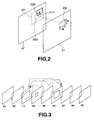
- reference block RB of MxN is set within reference frame 41.
- search (test) block SB of the same size as the reference block RB is set within retrieval frame 42.
- the search block SB is moved circulating within a predetermined search range 43 of ⁇ m x ⁇ n with the same position as the reference block RB being as center.
- the degree of correspondence between reference block RB and search (test) block SB is calculated to allow the search (test) block in which the degree of correspondence is maximum to be matching block to determine motion vector from this matching block.
- search (test) block SBk located at position shifted by (u, v) from search (test) block SB0 located at the same position as the reference block RB is maximum
- motion vector of that search (test) block SB is assumed to be (u, v).
- search (test) block in which sum total of absolute value differences every pixels or sum total of square of differences every pixels at respective corresponding positions of the reference block RB and search (test) block SB is minimum is assumed to be search (test) block in which the degree of correspondence is maximum.
- GOP Group of Picture
- the GOP consists of intraframe encoded pictures (I pictures), interframe encoded pictures (P pictures) predicted from already encoded frame forward in point of time, and interframe encoded pictures (B pictures) predicted from already encoded two frames before and after in point of time.
- P6 which is P picture is caused to be reference frame and I3 which is I picture is caused to be retrieval frame to carry out motion detection.
- B4 which is B picture is caused to be reference frame and 13 and P6 are caused to be retrieval frame to carry out motion detection in both directions (bidirectional motion detection).
- B5 which is B picture is caused to be reference frame and I3 and P6 are caused to be retrieval frame to carry out bidirectional motion detection.
- MEMORY-0 holds B1 until encoding has been completed.
- respective B frames they are similarly held in respective MEMORIES until they are encoded.
- I and P frames used as retrieval frame are stored into the respective frame memories until forward and backward motion vectors of respective frames are detected, i.e., for time periods during which those frames are required as retrieval frame for detecting the motion vector.
- This invention has been made in view of the above-mentioned problems and its object is to provide a picture encoding method and a picture encoding apparatus which can reduce data transfer quantity of retrieval frame in carrying out bidirectional prediction.
- Another object of this invention is to provide a picture encoding method and a picture encoding apparatus which can reduce capacity of memories for reference frame and retrieval frame.
- the above-mentioned picture encoding method is directed to a picture encoding method of carrying out motion detection from pictures in forward direction and in backward direction in point of time to carry out picture encoding, the method comprising: an input picture memory step of storing input picture to be encoded into a memory section; a forward motion detection step of detecting, from retrieval picture located in forward direction in point of time relative to first picture stored in the memory section at the input picture memory step, forward motion vector of the first picture; a backward motion detection step of detecting, from the retrieval picture, backward motion vector of second picture stored in the memory section at the input picture memory step and located forward in point of time relative to the retrieval picture; a motion vector preservation step of preserving, into a preservation section, the forward motion vector of the first picture detected by the forward motion detection step; and an encoding step of reading out, when encoding the first picture, the forward motion vector of the first picture from the motion vector preservation step to detect backward motion vector with respect to the first picture from the backward motion vector
- the first and second pictures are processed in plural block units obtained by dividing the input picture.
- the block matching method is used to detect motion vectors.
- a procedure is taken to determine, by calculation, picture data of reference block and picture data of retrieval block within retrieval range to detect motion vector in the forward direction and motion vector in the backward direction, whereby when motion vectors in the both directions are used to carry out encoding, detection timing of motion vector in one direction is shifted forward in point of time relative to encoding timing to thereby allow at least a portion of picture data of the retrieval block to be common to detection of motion vectors in the both directions.
- motion vector detected forward in point of time relative to the encoding timing is preserved (stored) into the preservation section to read out it in correspondence with the encoding timing.
- a picture encoding apparatus is directed to a picture encoding apparatus adapted for carrying out motion detection from pictures in forward and backward directions in point of time to carry out picture encoding, the apparatus comprising: input picture memory means for storing input picture to be encoded; forward motion detecting means for detecting, from retrieval picture located in forward direction in point of time relative to first picture stored by the input picture memory means, forward motion vector of the first picture; backward motion detecting means for detecting, from the retrieval picture, backward motion vector of second picture stored in the input picture memory means and located forward in point of time relative to the retrieval picture; motion vector preserving means for preserving the forward motion vector of the first picture detected by the forward motion detecting means; and encoding means for reading out, when encoding the first picture, the forward motion vector of the first picture from the motion vector preserving means to detect backward motion vector with respect to the first picture from the backward motion vector detecting means to carry out encoding by using these motion vectors in the forward and backward directions.
- the first and second pictures are processed in plural block units obtained by dividing the input picture.
- the motion detecting means in forward and backward directions detect motion vectors by using the block matching method.
- the motion vector detecting circuit is composed of a reference frame memory 11, a retrieval frame memory 12, a forward prediction motion detecting circuit 13, a backward prediction motion detecting circuit 14, a forward prediction motion vector/residual preservation memory 15, and a motion compensation mode judging circuit 16.
- the retrieval frame memory 12 serves to store picture of retrieval frame. Further, retrieval block data b is read out therefrom, and is inputted commonly to the forward prediction motion detecting circuit 13 and the backward prediction motion detecting circuit 14.
- the forward prediction motion detecting circuit 13 determines forward prediction motion vector c1 and its residual d1 to output them to the forward prediction motion vector/residual preservation memory 15.
- forward prediction motion vector/residual preservation memory 15 the forward prediction motion vector c1 and the residual d1 which are inputted thereto are preserved (stored). Simultaneously therewith, forward prediction motion vector c2 and residual d2 which have been already preserved (stored) are read out, and are inputted to the motion compensation mode judging circuit 16.
- the backward prediction motion detecting circuit 14 determines backward prediction motion vector e and its residual f to deliver them to the motion compensation mode judging circuit 16. This motion vector e is determined by the block matching method similarly to the prior art.
- the motion compensation mode judging circuit 16 carries out, by using data inputted thereto, judgment of motion compensation mode, and detection of motion vector and residual, etc. to output its result g.
- FIG. 6 is a block diagram showing a second form of the motion vector detecting circuit.
- the motion vector detecting circuit shown in FIG. 6 collectively represents, as a single memory 21, the reference frame memory 11, the retrieval frame memory 12 and the forward prediction motion vector/residual preservation memory 15 in FIG. 5, and the signal line is caused to be bus form.
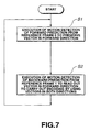
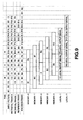
- FIG. 8 The operation of the motion vector detecting circuit shown in these FIGS. 5 and 6 will be described with reference to the flowchart of FIG. 7. In addition, operation timing is shown in FIG. 8.
- reference frame 0 is not encoded frame, and motion vector in forward direction from the reference frame 0 and its residual are preserved (stored) into forward prediction motion vector/residual preservation memory 15 at step S 1. Further, at time to be encoded, at step S2, backward predictive vector from the reference frame 1 is determined and the motion vector in forward direction and its residual which have been preserved at the step S1 are read out to carry out encoding of the reference frame 1. At times subsequent thereto, such operation will be repeated.
- data of frame B7 is further transferred as reference block data, and forward motion vector from the frame B7 to frame P6 and its residual are detected.
- those data are written into bank MV1 of the forward prediction motion vector/residual preservation memory 15.
- the forward motion vector and the residual are read out at time t2, and are used for encoding frame B7.
- retrieval data of one kind (data of frame P6 at time t1) and reference block data of two kinds (data of frame B7 and frame B4 at time t1) are transferred at all times to carry out read/write operation of forward motion vector and its residual with respect to the memory to thereby determine motion vectors in both directions required for bidirectional prediction.
- encoding using bidirectional prediction can be made. Namely, such an approach is employed to shift timing at which motion vector in forward direction and its residual are detected relative to timing of detection of motion vector in backward direction and its residual (thus also relative to encoding timing) to thereby allow retrieval data of one kind to be common to reference block data of two kinds.
- transfer quantity of retrieval data is reduced. It is to be noted that in the case where residual is not required for processing, it is not necessarily required to preserve (store) such residual.
- the number of frame memories used as the reference memory 11 and the retrieval frame memory 12 can be reduced to more degree as compared to the number of conventional frame memories, which has been described with reference to FIG. 4. This reduction of frame memories will be described below with reference to FIG. 9.
- transfer quantity of retrieval data can be reduced. Further, reduction of transfer quantity of data permits reduction of bus width from the memory and low speed of transfer clock. For this reason, realization by hardware becomes easy. As a result, reduced cost of hardware and low power consumption thereof can be realized. In addition, capacity of the memory for storing original picture can be reduced.
Landscapes
- Engineering & Computer Science (AREA)
- Multimedia (AREA)
- Signal Processing (AREA)
- Compression Or Coding Systems Of Tv Signals (AREA)
Claims (8)
- Bildcodierverfahren zum zeitlichen Ausführen von Bewegungsermittlung von Bildern in Vorwärts- und Rückwärtsrichtungen, um Bildcodierung auszuführen,
wobei das Verfahren aufweist:einen Eingabebild-Speicherschritt zum Speichern des zugeführten Bilds, um in einem Speicherabschnitt codiert zu werden, dadurch gekennzeichnet, dasseinen Vorwärtsbewegungs-Ermittlungsschritt zum Ermitteln - von dem abgerufenen Bild, welches in der Vorwärtsrichtung angeordnet ist, zeitlich in Bezug auf das erste Bild, welches im Speicherabschnitt Eingabebild-Speicherschritt gespeichert ist ― des Vorwärtsbewegungsvelctors des ersten Bilds;einen Rückwärtsbewegungs-Ermittlungsschritt zum Ermitteln - von dem abgerufenen Bild ― des Rückwärtsbewegungsvektors des zweiten Bilds, welches im Speicherabschnitt im Eingabebild-Speicherschritt gespeichert wurde und zeitlich vorher in Bezug auf das abgerufene Bild angeordnet ist;eine Bewegungsvektor-Aufrechterhaltungsschritt zum Aufrechterhalten des Vorwärtsbewegungsvektors des ersten Bilds, welches durch den Vorwärtsbewegungs-Ermittlungsschritt ermittelt wurde, in einem Aufrechterhaltungsabschnitt; undeinen Codierschritt zum Lesen, wenn das erste Bild codiert wird, des Vorwärtsbewegungsvektors des ersten Bilds vom Bewegungsvektor-Aufrechterhaltungsschritt, um einen Rückwärtsbewegungsvektor in Bezug auf das erste Bild vom Rückwärtsbewegungs-Vektorermittlungsschritt zu ermitteln, um Codieren unter Verwendung dieser Bewegungsvektoren in den Vorwärts- und Rückwärtsrichtungen auszuführen. - Bildcodierverfahren nach Anspruch 1,
wobei die ersten und zweiten Bilder in mehreren Blockeinheiten, die durch Unterteilen des Eingabebilds erhalten werden, verarbeitet werden. - Bildcodierverfahren nach Anspruch 2,
wobei in den Vorwärts- und Rückwärtsbewegungs-Ermittlungsschritten der Bewegungsvektor unter Verwendung des Blockanpassungsverfahrens ermittelt wird. - Bildcodierverfahren zum Ermitteln - durch Berechnung - von Referenzblock-Bilddaten und Abfrageblock-Bilddaten innerhalb des Abfragebereichs, um einen Bewegungsvektor in der Vorwärtsrichtung und einen Bewegungsvektor in der Rückwärtsrichtung zu ermitteln, dadurch gekennzeichnet, dass, wenn diese Bewegungsvektoren in beiden Richtungen verwendet werden, um Codieren auszuführen, der Ermittlungszeitablauf des Bewegungsvektors in einer Richtung zeitlich nach vorne in Bezug auf den Codierzeitpunkt verschoben wird, um dadurch zuzulassen, dass zumindest ein Bilddatenbereich des abgerufenen Blocks gemeinsam zur Bewegungsvektorermittlung in beiden Richtungen ist.
- Bildcodierverfahren nach Anspruch 4,
wobei der Bewegungsvektor, der vor dem Zeitpunkt in Bezug auf den Codierzeitpunkt ermittelt wird, in einem Aufrechterhaltungsabschnitt aufrechterhalten wird, um diesen gemäß dem Codierzeitpunkt auszulesen. - Bildcodiervorrichtung, die eingerichtet ist, zeitlich Bewegungsermittlung von Bildern in Vorwärts- und Rückwärtsrichtungen auszuführen, um Bildcodierung auszuführen,
wobei die Vorrichtung aufweist:eine Eingabebild-Speichereinrichtung zum Speichern des zugeführten Bilds, welches zu codieren ist, gekennzeichnet durcheine Vorwärtsbewegungs-Ermittlungseinrichtung zum Ermitteln ― aus dem abgerufenen Bild, welches in der Vorwärtsrichtung im Zeitpunkt in Bezug auf das erste Bild angeordnet ist, welches durch die Eingabebild-Speichereinrichtung gespeichert ist, ― des Vorwärtsbewegungsvektors des ersten Bilds;eine Rückwärtsbewegungs-Ermittlungseinrichtung zum Ermitteln - aus dem abgerufenen Bild ― des Rückwärtsbewegungsvektors des zweiten Bilds, welches in der Eingabebild-Speichereinrichtung gespeichert ist und welches zeitlich vorne in Bezug auf das abgerufene Bild angeordnet ist;eine Bewegungsvektor-Aufrechterhaltungseinrichtung zum Aufrechterhalten des Vorwärtsbewegungsvektors des ersten Bilds, welches durch die Vorwärtsbewegungs-Ermittlungseinrichtung ermittelt wird; undeine Codiereinrichtung zum Lesen ― wenn das erste Bild codiert wird ― des Vorwärtsbewegungsvektors des ersten Bilds von der Bewegungsvektor-Aufrechterhaltungseinrichtung, um einen Rückwärtsbewegungsvektor in Bezug auf das erste Bild von der Rückwärtsbewegungs-Vektorermittlungseinrichtung zu ermitteln, um Codieren unter Verwendung dieser Bewegungsvektoren in den Vorwärts- und Rückwärtsrichtungen auszuführen. - Bildcodiervorrichtung nach Anspruch 6,
wobei die ersten und zweiten Bilder in mehreren Blockeinheiten, welche durch Teilen des zugeführten Bilds erhalten werden, verarbeitet werden. - Bildcodiervorrichtung nach Anspruch 7,
wobei die Bewegungsermittlungseinrichtung in den Vorwärts- und Rückwärtsrichtungen einen Bewegungsvektor unter Verwendung des Blockanpassungsverfahrens ermitteln.
Applications Claiming Priority (3)
| Application Number | Priority Date | Filing Date | Title |
|---|---|---|---|
| JP6586897 | 1997-03-19 | ||
| JP65868/97 | 1997-03-19 | ||
| PCT/JP1998/000899 WO1998042136A1 (en) | 1997-03-19 | 1998-03-04 | Image encoding method and device |
Publications (3)
| Publication Number | Publication Date |
|---|---|
| EP0909097A1 EP0909097A1 (de) | 1999-04-14 |
| EP0909097A4 EP0909097A4 (de) | 2001-11-28 |
| EP0909097B1 true EP0909097B1 (de) | 2006-06-07 |
Family
ID=13299410
Family Applications (1)
| Application Number | Title | Priority Date | Filing Date |
|---|---|---|---|
| EP98905764A Expired - Lifetime EP0909097B1 (de) | 1997-03-19 | 1998-03-04 | Verfahren und vorrichtung zur bildkodierung |
Country Status (4)
| Country | Link |
|---|---|
| US (1) | US6005628A (de) |
| EP (1) | EP0909097B1 (de) |
| DE (1) | DE69834788T2 (de) |
| WO (1) | WO1998042136A1 (de) |
Families Citing this family (1)
| Publication number | Priority date | Publication date | Assignee | Title |
|---|---|---|---|---|
| CA2456377C (en) | 2001-11-06 | 2013-01-15 | Matsushita Electric Industrial Co., Ltd. | Moving picture coding method, and moving picture decoding method |
Family Cites Families (13)
| Publication number | Priority date | Publication date | Assignee | Title |
|---|---|---|---|---|
| JPS61200789A (ja) * | 1985-03-04 | 1986-09-05 | Kokusai Denshin Denwa Co Ltd <Kdd> | 画面上の物体の動きベクトル検出方式 |
| US5198901A (en) * | 1991-09-23 | 1993-03-30 | Matsushita Electric Corporation Of America | Derivation and use of motion vectors in a differential pulse code modulation system |
| JPH05137131A (ja) * | 1991-11-13 | 1993-06-01 | Sony Corp | フレーム間動き予測方法 |
| JPH06233285A (ja) * | 1993-01-30 | 1994-08-19 | Victor Co Of Japan Ltd | 動画像圧縮方法 |
| JP3050736B2 (ja) * | 1993-12-13 | 2000-06-12 | シャープ株式会社 | 動画像符号化装置 |
| JP3360942B2 (ja) * | 1994-06-20 | 2003-01-07 | 沖電気工業株式会社 | 動画像符号化装置 |
| KR0126871B1 (ko) * | 1994-07-30 | 1997-12-29 | 심상철 | 양방향 이동벡터 추정을 위한 고속 블럭정합 방식 |
| JPH0865685A (ja) * | 1994-08-23 | 1996-03-08 | Nec Corp | 動きベクトル検出回路 |
| TW311316B (de) * | 1995-01-30 | 1997-07-21 | Hitachi Ltd | |
| KR0171145B1 (ko) * | 1995-03-20 | 1999-03-20 | 배순훈 | 이미지 부호화 시스템용 움직임 보상 장치 |
| US5886744A (en) * | 1995-09-08 | 1999-03-23 | Intel Corporation | Method and apparatus for filtering jitter from motion estimation video data |
| US5682209A (en) * | 1995-11-13 | 1997-10-28 | Tektronix, Inc. | Motion estimation using limited-time early exit with prequalification matrices and a predicted search center |
| JPH09238351A (ja) * | 1996-02-29 | 1997-09-09 | Canon Inc | 画像符号化装置 |
-
1998
- 1998-03-04 DE DE69834788T patent/DE69834788T2/de not_active Expired - Fee Related
- 1998-03-04 EP EP98905764A patent/EP0909097B1/de not_active Expired - Lifetime
- 1998-03-04 WO PCT/JP1998/000899 patent/WO1998042136A1/ja active IP Right Grant
- 1998-11-17 US US09/193,433 patent/US6005628A/en not_active Expired - Fee Related
Also Published As
| Publication number | Publication date |
|---|---|
| EP0909097A4 (de) | 2001-11-28 |
| US6005628A (en) | 1999-12-21 |
| WO1998042136A1 (en) | 1998-09-24 |
| EP0909097A1 (de) | 1999-04-14 |
| DE69834788T2 (de) | 2007-05-16 |
| DE69834788D1 (de) | 2006-07-20 |
Similar Documents
| Publication | Publication Date | Title |
|---|---|---|
| EP0821857B1 (de) | Bilddekodiergerät und methode unter verwendung eines nicht-referenzbildes als zusätzliche vorhersagequelle | |
| EP1065883B1 (de) | Prädiktives Bilddekodierungsverfahren | |
| US5539466A (en) | Efficient coding apparatus for picture signal and decoding apparatus therefor | |
| US6542642B2 (en) | Image coding process and motion detecting process using bidirectional prediction | |
| EP1096800B1 (de) | Bildkodierungsgerät und Bilddekodierungsgerät | |
| US5841475A (en) | Image decoding with dedicated bidirectional picture storage and reduced memory requirements | |
| JP2962012B2 (ja) | 動画像符号化装置及びその復号装置 | |
| EP0542195B1 (de) | Verfahren zum Bild-zu-Bild-Prädiktion und Bildsignal-Kodier/Dekodiervorrichtung | |
| KR0168458B1 (ko) | 움직임 보상을 갖는 프레임간 혼성 부호기에서의 왜곡을 감소시키는 장치 및 방법 그리고 그에 대한 부호화 시스템 | |
| KR100556340B1 (ko) | 영상 부호화 장치 | |
| US6415055B1 (en) | Moving image encoding method and apparatus, and moving image decoding method and apparatus | |
| US5103307A (en) | Interframe predictive coding/decoding system for varying interval between independent frames | |
| US5809173A (en) | Method and apparatus for improved video decompression using previous frame DCT coefficients | |
| EP0598904A1 (de) | Bildsignalkodierungs/dekodierungsvorrichtung mit hoher wirkungsgrad | |
| US5991445A (en) | Image processing apparatus | |
| US6263112B1 (en) | Motion vector searching apparatus and motion picture coding apparatus | |
| US6353683B1 (en) | Method and apparatus of image processing, and data storage media | |
| US6097843A (en) | Compression encoding apparatus, encoding method, decoding apparatus, and decoding method | |
| EP0909097B1 (de) | Verfahren und vorrichtung zur bildkodierung | |
| US5485214A (en) | Dual bus dual bank architecture for motion compensation | |
| JPH0221776A (ja) | 予測性静止画像エンコーダ・デコーダ | |
| JP2776284B2 (ja) | 画像符号化装置 | |
| KR100504416B1 (ko) | 화상부호화방법및장치 | |
| JP3692613B2 (ja) | 情報処理方法及び情報処理装置 | |
| JP3549175B2 (ja) | 動きベクトル検出方法および装置 |
Legal Events
| Date | Code | Title | Description |
|---|---|---|---|
| PUAI | Public reference made under article 153(3) epc to a published international application that has entered the european phase |
Free format text: ORIGINAL CODE: 0009012 |
|
| 17P | Request for examination filed |
Effective date: 19981125 |
|
| AK | Designated contracting states |
Kind code of ref document: A1 Designated state(s): DE FR GB |
|
| A4 | Supplementary search report drawn up and despatched |
Effective date: 20011015 |
|
| AK | Designated contracting states |
Kind code of ref document: A4 Designated state(s): DE FR GB |
|
| RIC1 | Information provided on ipc code assigned before grant |
Free format text: 7H 04N 7/32 A, 7H 04N 7/46 B, 7H 04N 7/50 B |
|
| GRAP | Despatch of communication of intention to grant a patent |
Free format text: ORIGINAL CODE: EPIDOSNIGR1 |
|
| GRAS | Grant fee paid |
Free format text: ORIGINAL CODE: EPIDOSNIGR3 |
|
| GRAA | (expected) grant |
Free format text: ORIGINAL CODE: 0009210 |
|
| AK | Designated contracting states |
Kind code of ref document: B1 Designated state(s): DE FR GB |
|
| REG | Reference to a national code |
Ref country code: GB Ref legal event code: FG4D |
|
| REF | Corresponds to: |
Ref document number: 69834788 Country of ref document: DE Date of ref document: 20060720 Kind code of ref document: P |
|
| ET | Fr: translation filed | ||
| PLBE | No opposition filed within time limit |
Free format text: ORIGINAL CODE: 0009261 |
|
| STAA | Information on the status of an ep patent application or granted ep patent |
Free format text: STATUS: NO OPPOSITION FILED WITHIN TIME LIMIT |
|
| 26N | No opposition filed |
Effective date: 20070308 |
|
| PGFP | Annual fee paid to national office [announced via postgrant information from national office to epo] |
Ref country code: GB Payment date: 20090304 Year of fee payment: 12 |
|
| PGFP | Annual fee paid to national office [announced via postgrant information from national office to epo] |
Ref country code: DE Payment date: 20090226 Year of fee payment: 12 |
|
| PGFP | Annual fee paid to national office [announced via postgrant information from national office to epo] |
Ref country code: FR Payment date: 20090316 Year of fee payment: 12 |
|
| GBPC | Gb: european patent ceased through non-payment of renewal fee |
Effective date: 20100304 |
|
| REG | Reference to a national code |
Ref country code: FR Ref legal event code: ST Effective date: 20101130 |
|
| PG25 | Lapsed in a contracting state [announced via postgrant information from national office to epo] |
Ref country code: FR Free format text: LAPSE BECAUSE OF NON-PAYMENT OF DUE FEES Effective date: 20100331 |
|
| PG25 | Lapsed in a contracting state [announced via postgrant information from national office to epo] |
Ref country code: DE Free format text: LAPSE BECAUSE OF NON-PAYMENT OF DUE FEES Effective date: 20101001 |
|
| PG25 | Lapsed in a contracting state [announced via postgrant information from national office to epo] |
Ref country code: GB Free format text: LAPSE BECAUSE OF NON-PAYMENT OF DUE FEES Effective date: 20100304 |