EP0908928A2 - Baking furnace and control method therefor - Google Patents
Baking furnace and control method therefor Download PDFInfo
- Publication number
- EP0908928A2 EP0908928A2 EP98119051A EP98119051A EP0908928A2 EP 0908928 A2 EP0908928 A2 EP 0908928A2 EP 98119051 A EP98119051 A EP 98119051A EP 98119051 A EP98119051 A EP 98119051A EP 0908928 A2 EP0908928 A2 EP 0908928A2
- Authority
- EP
- European Patent Office
- Prior art keywords
- baking furnace
- disposed
- front chamber
- air
- inlet
- Prior art date
- Legal status (The legal status is an assumption and is not a legal conclusion. Google has not performed a legal analysis and makes no representation as to the accuracy of the status listed.)
- Granted
Links
- 238000000034 method Methods 0.000 title claims description 12
- 238000010438 heat treatment Methods 0.000 claims description 42
- 239000000463 material Substances 0.000 claims description 17
- 238000005259 measurement Methods 0.000 claims description 2
- 238000010276 construction Methods 0.000 description 9
- 239000000567 combustion gas Substances 0.000 description 6
- 239000003989 dielectric material Substances 0.000 description 4
- 238000007599 discharging Methods 0.000 description 4
- 239000011521 glass Substances 0.000 description 4
- 230000000694 effects Effects 0.000 description 3
- 239000004065 semiconductor Substances 0.000 description 3
- 230000007423 decrease Effects 0.000 description 2
- 238000004519 manufacturing process Methods 0.000 description 2
- 239000000919 ceramic Substances 0.000 description 1
- 239000002184 metal Substances 0.000 description 1
- 238000011144 upstream manufacturing Methods 0.000 description 1
Images


Classifications
-
- H—ELECTRICITY
- H01—ELECTRIC ELEMENTS
- H01L—SEMICONDUCTOR DEVICES NOT COVERED BY CLASS H10
- H01L21/00—Processes or apparatus adapted for the manufacture or treatment of semiconductor or solid state devices or of parts thereof
- H01L21/67—Apparatus specially adapted for handling semiconductor or electric solid state devices during manufacture or treatment thereof; Apparatus specially adapted for handling wafers during manufacture or treatment of semiconductor or electric solid state devices or components ; Apparatus not specifically provided for elsewhere
- H01L21/67005—Apparatus not specifically provided for elsewhere
- H01L21/67011—Apparatus for manufacture or treatment
- H01L21/67098—Apparatus for thermal treatment
- H01L21/67109—Apparatus for thermal treatment mainly by convection
-
- F—MECHANICAL ENGINEERING; LIGHTING; HEATING; WEAPONS; BLASTING
- F27—FURNACES; KILNS; OVENS; RETORTS
- F27B—FURNACES, KILNS, OVENS, OR RETORTS IN GENERAL; OPEN SINTERING OR LIKE APPARATUS
- F27B9/00—Furnaces through which the charge is moved mechanically, e.g. of tunnel type; Similar furnaces in which the charge moves by gravity
- F27B9/14—Furnaces through which the charge is moved mechanically, e.g. of tunnel type; Similar furnaces in which the charge moves by gravity characterised by the path of the charge during treatment; characterised by the means by which the charge is moved during treatment
- F27B9/20—Furnaces through which the charge is moved mechanically, e.g. of tunnel type; Similar furnaces in which the charge moves by gravity characterised by the path of the charge during treatment; characterised by the means by which the charge is moved during treatment the charge moving in a substantially straight path tunnel furnace
- F27B9/24—Furnaces through which the charge is moved mechanically, e.g. of tunnel type; Similar furnaces in which the charge moves by gravity characterised by the path of the charge during treatment; characterised by the means by which the charge is moved during treatment the charge moving in a substantially straight path tunnel furnace being carried by a conveyor
- F27B9/2407—Furnaces through which the charge is moved mechanically, e.g. of tunnel type; Similar furnaces in which the charge moves by gravity characterised by the path of the charge during treatment; characterised by the means by which the charge is moved during treatment the charge moving in a substantially straight path tunnel furnace being carried by a conveyor the conveyor being constituted by rollers (roller hearth furnace)
-
- F—MECHANICAL ENGINEERING; LIGHTING; HEATING; WEAPONS; BLASTING
- F27—FURNACES; KILNS; OVENS; RETORTS
- F27B—FURNACES, KILNS, OVENS, OR RETORTS IN GENERAL; OPEN SINTERING OR LIKE APPARATUS
- F27B9/00—Furnaces through which the charge is moved mechanically, e.g. of tunnel type; Similar furnaces in which the charge moves by gravity
- F27B9/30—Details, accessories, or equipment peculiar to furnaces of these types
- F27B9/3005—Details, accessories, or equipment peculiar to furnaces of these types arrangements for circulating gases
-
- F—MECHANICAL ENGINEERING; LIGHTING; HEATING; WEAPONS; BLASTING
- F27—FURNACES; KILNS; OVENS; RETORTS
- F27B—FURNACES, KILNS, OVENS, OR RETORTS IN GENERAL; OPEN SINTERING OR LIKE APPARATUS
- F27B9/00—Furnaces through which the charge is moved mechanically, e.g. of tunnel type; Similar furnaces in which the charge moves by gravity
- F27B9/30—Details, accessories, or equipment peculiar to furnaces of these types
- F27B9/40—Arrangements of controlling or monitoring devices
Definitions
- the present invention relates to a baking furnace and a control method therefor, which are used for the baking of electrodes for plasma displays or semiconductors and the baking of paste for dielectrics.
- a baking furnace is an indispensable device for a process which involves the baking of electrodes of plasma displays or semiconductors or the baking of paste for dielectrics.
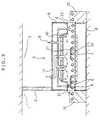
- the construction of a conventional baking furnace will now be described using a sectional view in Fig. 5.
- a conventional baking furnace 4 comprises transfer rollers 5, a muffle 6 made of heat resistant glass, a heater 7, a cover, an air feed pipe system 10, an exhaust pipe 11, and an inlet conveyor 15, an outlet conveyor 20.
- the muffle 6 is in the form of a flat box rectangular in cross section, extending from the inlet 31 to the outlet 32 of the baking furnace 4.
- the heater 7 is disposed on the outer periphery of the muffle 6.
- the air feed pipe system 10 is connected to the muffle 6 to feed air 9 into the latter.
- the exhaust pipe 11 is a pipe for discharging combustion gases in the muffle 6 to the outside of the baking furnace 4.
- the muffle 6 and heater 7 are covered by a cover 8.
- An inlet conveyor 15 is disposed at the inlet 31 of the baking furnace 4 and an outlet conveyor 20 at the outlet 32. Boards 21 supported on support plates 22 enter the baking furnace 4 from the inlet conveyor 15 and are baked as they are transferred in the muffle 6 by the transfer rollers 5 until they are taken out onto the outlet conveyor 20.
- the inlet 31 of the conventional baking furnace 4 is positioned on the side associated with a clean room 1.
- the outlet 32 of the baking furnace 4 is positioned on the side associated with a normal pressure room 2.
- the clean room 1 and the normal pressure room 2 are separated by a wall 3.
- the clean room 1 is about 5 - 10 Pa higher in pressure than the normal pressure room 2.
- the difference in pressure between the inlet 31 and outlet 32 of the baking furnace 4 causes the air in the clean room 1 to flow in the muffle 6 from the inlet 31 to the outlet 32 of the baking furnace 4.
- the difference in pressure between the clean room 1 and the normal pressure room 2 is 10 Pa
- the flow rate of the air flowing in the muffle 6 is 4 m/sec, and in the case of 5 Pa, it is 3 m/sec. Since the cool air in the clean room 1 flows into the baking furnace 4 at said flow rate, the temperature distribution in the muffle 6 varies, presenting a problem that the baking conditions vary to the extent that a baked product of predetermined baking quality cannot be obtained.
- the present invention is intended to solve said problems and provide a baking furnace and a control method therefor, by which a baked product of predetermined baking quality can be obtained.
- a baking furnace comprises a heating chamber having an inlet disposed in a first space and an outlet disposed in a second space whose pressure is lower than that of the first space, said inlet and outlet being for a material to be heated, transfer means disposed in said heating chamber for transferring the material to be heated which has been transferred to said heating chamber, heating means disposed in the vicinity of said heating chamber, air discharge means connected to a place in the vicinity of the inlet of said heating chamber, differential pressure detecting means installed outside said heating chamber for detecting the difference in pressure between said first and second spaces, and discharge control means for controlling the operation of said air discharge means on the basis of information from said differential pressure detecting means.
- the air flowing from the inlet into a space in the vicinity of the inlet of the heating chamber can be discharged to the outside of the baking furnace by using the air discharge means installed in the vicinity of the inlet, thus making it possible to prevent the air from flowing into the innermost region of the heating chamber. Therefore, the temperature distribution in the baking furnace can be maintained constant, whereby a baked product of predetermined baking quality can be obtained.
- the baking furnace comprises a front chamber whose inlet disposed in a first space is provided with opening and closing means, a heating chamber connected to said front chamber through an opening and having an outlet disposed in a second space whose pressure is lower than that of said first space, heating means disposed in the vicinity of said heating chamber, first transfer means installed in said front chamber for transferring a material to be heated by switching the transfer speed between high and low, and second transfer means installed in said heating chamber for transferring said material at low speed.
- the opening and closing means is closed except when the material is transferred to the front chamber and since the material can be transferred at high seed to the front chamber, the time during which the opening and closing means is opened can be shortened.
- the amount of air flowing through the inlet into the front chamber can be minimized and the air can be substantially prevented from flowing into the heating chamber.
- the temperature distribution in the baking furnace can be maintained constant and a baked product of predetermined baking quality can be obtained.
- this baking furnace is simpler in construction, making it possible to reduce the production costs thereof.
- a baking furnace comprises a front chamber having an inlet disposed in a first space, a heating chamber connected to said front chamber through an opening and having an outlet disposed in a second space whose pressure is lower than that of said first space, transfer means disposed in said front chamber and heating chamber for transferring a material to be heated, heating means disposed in the vicinity of the heating chamber, and an air discharge pipe having a suction port at one end thereof connected to the front chamber and an exhaust port at the other end disposed in the second space.
- the cross sectional area of the air discharge pipe can be made greater than that of the opening in the baking furnace inlet, and the air flowed into the front chamber flows only little in the direction of the baking furnace, most of the air being discharged through the air discharge pipe. Further, the construction can be made simpler.
- a baking furnace according to the invention is provided with discharge assisting means for facilitating air flowed into said front chamber through said inlet to flow toward said air discharge pipe.
- the air flowed into the front chamber can be guided in the direction of the air discharge pipe by the discharge assisting means, so that the air can be discharged mostly through the air discharge pipe.
- a control method for controlling a baking furnace described in Claim 1 or 2 of the invention comprises the steps of measuring the difference in pressure between said first and second spaces by said differential pressure detecting means, and controlling the amount of air being discharged by said air discharge means by said discharge control means according to the results of the measurement.
- the amount of air being discharged by said air discharge means can be changed according to the differential pressure detected by the differential pressure detecting means, so that the air can be discharged only by an amount equal to the amount of the air which has been flowed in, thus preventing the air from flowing into the heating chamber.
- a control method for controlling a baking furnace described in Claim 4 of the invention comprises the steps of closing said opening and closing means except when said material to be heated is transferred to said front chamber, and transferring said material at high speed to said front chamber by said first transfer means, thereby restricting the air from flowing into said baking furnace.
- the amount of air flowing into the front chamber is restricted to being very small, so that the air flowed into the front chamber can be prevented from flowing directly into the heating chamber.
- FIG. 1 is a sectional view
- Fig. 2 is a sectional view taken along the line Z-Z in Fig. 1.
- arrangements which are the same as in the prior example described above are denoted by the same reference characters.
- a baking furnace 4 lies across the boundary between a clean room 1 and a normal pressure room 2.
- the clean room 1 and the normal pressure room 2 are separated by a wall 3.
- the pressure in the clean room 1 is controlled so that it is 5-10 Pa higher than that of the normal pressure room 2.
- the baking furnace 4 comprises a muffle 6 forming a heating chamber, transfer rollers 5 disposed to extend from the inlet to the outlet of the muffle 6, a heater 7 disposed on the outer periphery of the muffle 6 for heating boards 21 to be baked, a cover 8 which covers the muffle 6 and heater 7, an air feed pipe system 10 having a plurality of spouts for feeding air into the muffle 6, an exhaust pipe 11 having suction ports disposed in the upper region of the muffle 6 for discharging combustion gases in the muffle 6, a front chamber 24 composed of a hood 12 and an airtight cover 13, a control plate 14 for controlling the opening of the inlet 31 of the front chamber 24, an inlet conveyor 15 disposed in the inlet of the muffle 6, a differential pressure gauge (differential pressure detecting means) 16 for measuring the difference in pressure between the clean room 1 and the normal pressure room 2, a controller 17 for producing a control signal from the results of the differential pressure gauge 16, a frequency-variable inverter 18, an exhaust fan 19 for discharging
- the transfer rollers 5 are driven by a driving source (not shown).
- the muffle 6 is in the form of a flat box rectangular in cross section, extending from the inlet of the baking furnace 4, i.e., an opening 33 in the latter, to the outlet 32.
- the heater 7 is disposed on the outer periphery of the muffle 6.
- the air feed pipe system 10 is used to feed air 9 into the muffle 6, having spouts for air 9 disposed respectively in the vicinity of the inlet of the baking furnace 4, in the muffle 6, and in the vicinity of the outlet of the barking furnace 4.
- the suction ports of the exhaust pipe 11 are attached in the muffle 6 for discharging combustion gases in the muffle 6 into the outside of the baking furnace 4.
- the hood 12 is installed at the inlet of the baking furnace 4 and has an exhaust port disposed in the upper portion thereof.
- the airtight cover 13 is disposed in a lower surface for the transfer rollers 5 within the hood 12, whereby the air flowed into the front chamber 24 from the clean room 1 is prevented from leaking through the lower surface for the transfer rollers 5.
- the hood 12 and airtight cover 13 are integrally combined to constitute the front chamber 24 of the baking furnace 4.
- the front chamber 24 is formed with the inlet 31 for transfer.
- the control plate 14 is disposed at the inlet 31 of the front chamber 24 and controls the amount of air flowing from the clean room 1 into the front chamber 24.
- the inlet conveyor 15 is disposed at the inlet 31 of the front chamber 24, while the outlet conveyor 20 is disposed at the outlet 32 of the baking furnace 4.
- the differential pressure gauge 16 comprises a first measuring port 16a having an end disposed in the normal pressure room 2, and a second measuring port 16b having an end disposed in the clean room 1.
- the controller 17 changes the frequency of the inverter 18 according to the output from the differential pressure gauge 16 so as to control the rpm of the exhaust fan 19 and control the amount of discharge of air.
- the exhaust from the exhaust fan 19 is disposed in a return duct 23 leading to the clean room 1; thus, it is arranged that the exhaust is returned to the clean room 1.
- the support plates 22 are moved by the transfer rollers 5, traveling through the inlet 31 of the front chamber 24 and the opening 33 in the baking furnace 4 to the outlet 33 of the baking furnace 4.
- the support plates 22 are heat resistant boards whose size is, for example, 850 mm long, 1300 mm wide and 5 mm thick.
- the boards 21 to be baked are, for example, glass plates coated with paste, being 554 mm long, 980 mm wide and 2.8 mm thick.
- the boards 21 supported on the support plates 22 are conveyed into the front chamber 24 by the inlet conveyor 15 and transferred through the front chamber 24 to the baking furnace 4 by the transfer rollers 5.
- the boards 21 are passed through the muffle 6 heated by the heater 7.
- the baking furnace 4 has been controlled to have a predetermined temperature distribution established therein.
- Fresh air 9 is fed into the muffle 6 through the air feed pipe system 10.
- Combustion gases are exhausted into the outside of the baking furnace 4 through the exhaust pipe 11.
- An adjustment has been made so that the feeding of air 9 into the baking furnace 4 and the exhaust of combustion gases are substantially balanced.
- the front chamber 24 is located upstream of the baking furnace 4, the control plate 14 is installed at the inlet of the front chamber 4, and the position of the control plate 14 is controlled to decrease the area of the opening.
- the opening 33 As an example of the opening 33, suppose that the width of the opening is 1500 mm and its height is 20 mm. Then, the area of the opening is 0.03 m 2 . With a differential pressure of 10 Pa, the air speed is 4 m 2 /sec; thus, it follows that 0.12 m 2 /sec of air flows into the baking furnace 4 through the inlet.
- the exhaust fan 19 is driven to discharge substantially the same amount of air into the clean room 1 as the amount of air flowed into the front chamber 24, thereby reducing to zero the air inflow from the clean room 1 into the baking furnace 4.
- the exhaust fan 19 is driven to discharge substantially the same amount of air into the clean room 1 as the amount of air flowed into the front chamber 24, thereby reducing to zero the air inflow from the clean room 1 into the baking furnace 4.
- the baking furnace 4 is operated in such a manner as to ensure that the difference in pressure between the clean room 1 and the normal pressure room 2 is constant at all times, in reality there is a variation of 5 - 10 Pa in pressure difference.
- the pressure difference is detected by the differential pressure gauge 16 and the frequency of the inverter 18 is changed by the controller 17 to change the rpm of the exhaust fan, thereby controlling the rate of discharge of air into the clean room 1.
- the hood 12 and airtight cover 13 are integrally formed to provide the front chamber 24 for the baking furnace 4 and the exhaust port is disposed in the top of the hood 12.
- a baking furnace having no front chamber 24 may be formed wherein said exhaust port is disposed directly in a place in the muffle close to the inlet of the baking furnace 4, and the air discharge means (inverter 18, exhaust fan 19, and return duct 23) and the discharge control means (differential pressure gauge 16 and controller 17) are installed, with the hood 12 and airtight cover 13 removed.
- a baking furnace 4 is installed across the boundary between a clean room 1 and a normal pressure room 2.
- the clean room 1 and the normal pressure room 2 are separated by a wall 3.
- the pressure in the clean room 1 is controlled so that it is 5 - 10 Pa higher than that of the normal pressure room 2.
- the baking furnace 4 comprises transfer rollers 5, a muffle 6, a heater 7, a cover 8, an air feed pipe system 10, an exhaust pipe 11, an inlet cover 25 constituting a front chamber 241, a shutter 26 disposed at the inlet 31 of the front chamber 241, a cylinder 30 for opening and closing the shutter 26, an inlet conveyor 15, a first motor 27, a second motor 28 and a third motor 29 for driving the transfer rollers 5, an outlet conveyor 20, and support plates 22.
- the muffle 6 is in the form of flat box rectangular in cross section, extending from the inlet of the baking furnace 4, i.e., an opening 33 in the latter, to the outlet 32.
- the heater 7 is disposed on the outer periphery of the muffle 6.
- the cover 8 covers the muffle 6 and heater 7.
- the air feed pipe system 10 serves to feed air 9 into the muffle 6, having spouts for air 9 respectively disposed in the vicinity of the inlet of the baking furnace 4, within the muffle 6, and in the vicinity of the outlet of the baking furnace 4.
- the suction ports of the exhaust pipe 11 are positioned in the muffle 6 to exhaust the combustion gases in the baking furnace 4 into the outside of the muffle 6.
- the place where the inlet cover 25 is installed is in the front chamber 241 of the baking furnace 4.
- the first motor 27 is a motor for driving the inlet conveyor 15, and the second motor 28 is a motor for driving the transfer rollers 5 in the front chamber 241 and adapted for switching between high and low driving speeds.
- the high driving speed is about 50 times the low driving speed.
- the third motor 29 is a motor for driving the transfer rollers 5 in the muffle 6, said motor being for low speed drive.
- the shutter 26 When the board 21 is completely in the front chamber 241, the shutter 26 is closed. When the board 21 has moved from the front chamber 241 completely into the baking furnace 4, the shutter 26 is opened and another board 21 is transferred at high driving speed from the conveyor 15 to the front chamber 241. The board 21 transferred to the front chamber 241 is transferred by the low speed driving of the transfer rollers 5 through the front chamber 241 to the muffle 6 while it is baked. When the shutter 26 is opened, the air in the clean room 1 flows at a speed corresponding to the differential pressure into the front chamber 241; however, since the board 21 is transferred at high driving speed, it is for only a few seconds that the shutter 26 is opened.
- the area of the opening is reduced by an amount equal to the sum of the thicknesses of the support plate 22 and the board 21, thus reducing the rate of air inflow.
- the time during which the shutter 26 is opened is very short, the amount of air flowing from the clean room 1 into the baking surface 4 can be minimized.
- the provision of the front chamber 241 provides an effect which ensures that the flow of air from the clean room 1 into the muffle 6 is buffered in the front chamber 241. Therefore, it is possible to prevent variation of the temperature distribution in the baking furnace 4. Further, in this construction, there is no need to provide discharge control means for controlling the air discharge means shown in the first embodiment, so that the construction of the entire baking furnace 4 is simple and the production costs of the baking furnace 4 can be lowered.
- FIG. 4 is a sectional view.
- the duct 34 is installed such that its suction port at one end thereof is connected to the front chamber 24 and its exhaust port at the other end is positioned within the normal pressure room 2.
- the cross sectional area of the duct 34 is larger than the area of the region which connects the front chamber 24 and the baking furnace 4. Thereby, most of the air flowing from the inlet 31 into the front chamber 24 can be discharged from the duct 34.
- the front chamber 24 may be internally provided with a plurality of valves 35 (discharge assisting means) so that the air flowing from the inlet 31 into the front chamber 24 may be guided to the duct 34. Thereby, the air flowing into the front chamber 24 can be discharged from the duct 34.
- the boards 21 have been shown as electrodes for plasma displays or glass boards coated with a dielectric paste; however, they may be simply glass boards, semiconductor boards, ceramics, metal or the like to be baked, there being no limitation to their uses.
- the muffle 6 has been described as a flat box rectangular in cross section; however, it may be of any shape so long as it is opened at its inlet and outlet.
- it may be a sleeve which is circular or elliptic in cross section.
- the inlet of the front chamber 24, 241 has been located in the clean room 1 and the outlet 32 of the baking furnace 4 has been located in the normal pressure room 2 which is lower in pressure than the clean room 1; however, the baking furnace 4 may be installed in any place so long as the pressure in the inlet 31 of the front chamber is higher than that in the outlet 32.
Landscapes
- Engineering & Computer Science (AREA)
- Mechanical Engineering (AREA)
- General Engineering & Computer Science (AREA)
- Manufacturing & Machinery (AREA)
- Condensed Matter Physics & Semiconductors (AREA)
- General Physics & Mathematics (AREA)
- Physics & Mathematics (AREA)
- Computer Hardware Design (AREA)
- Microelectronics & Electronic Packaging (AREA)
- Power Engineering (AREA)
- Furnace Details (AREA)
- Waste-Gas Treatment And Other Accessory Devices For Furnaces (AREA)
- Tunnel Furnaces (AREA)
- Muffle Furnaces And Rotary Kilns (AREA)
Abstract
Description
- The present invention relates to a baking furnace and a control method therefor, which are used for the baking of electrodes for plasma displays or semiconductors and the baking of paste for dielectrics.
- A baking furnace is an indispensable device for a process which involves the baking of electrodes of plasma displays or semiconductors or the baking of paste for dielectrics. The construction of a conventional baking furnace will now be described using a sectional view in Fig. 5.
- A
conventional baking furnace 4 comprisestransfer rollers 5, amuffle 6 made of heat resistant glass, aheater 7, a cover, an airfeed pipe system 10, anexhaust pipe 11, and aninlet conveyor 15, anoutlet conveyor 20. - The
muffle 6 is in the form of a flat box rectangular in cross section, extending from theinlet 31 to theoutlet 32 of thebaking furnace 4. Theheater 7 is disposed on the outer periphery of themuffle 6. The airfeed pipe system 10 is connected to themuffle 6 to feedair 9 into the latter. Theexhaust pipe 11 is a pipe for discharging combustion gases in themuffle 6 to the outside of thebaking furnace 4. Themuffle 6 andheater 7 are covered by acover 8. Aninlet conveyor 15 is disposed at theinlet 31 of thebaking furnace 4 and anoutlet conveyor 20 at theoutlet 32.Boards 21 supported onsupport plates 22 enter thebaking furnace 4 from theinlet conveyor 15 and are baked as they are transferred in themuffle 6 by thetransfer rollers 5 until they are taken out onto theoutlet conveyor 20. - The
inlet 31 of theconventional baking furnace 4 is positioned on the side associated with a clean room 1. Theoutlet 32 of thebaking furnace 4 is positioned on the side associated with anormal pressure room 2. The clean room 1 and thenormal pressure room 2 are separated by awall 3. The clean room 1 is about 5 - 10 Pa higher in pressure than thenormal pressure room 2. - In such
conventional baking furnace 4, since theinlet 31 is disposed on the side associated with the clean room 1 which is higher in pressure than theoutlet 32, the difference in pressure between theinlet 31 andoutlet 32 of thebaking furnace 4 causes the air in the clean room 1 to flow in themuffle 6 from theinlet 31 to theoutlet 32 of thebaking furnace 4. In the case where the difference in pressure between the clean room 1 and thenormal pressure room 2 is 10 Pa, the flow rate of the air flowing in themuffle 6 is 4 m/sec, and in the case of 5 Pa, it is 3 m/sec. Since the cool air in the clean room 1 flows into thebaking furnace 4 at said flow rate, the temperature distribution in themuffle 6 varies, presenting a problem that the baking conditions vary to the extent that a baked product of predetermined baking quality cannot be obtained. - For example, in the baking of electrodes for plasma displays or the baking of paste for dielectrics, there arises a problem that the yield of electrodes or dielectrics themselves decreases owing to temperature variations in the
muffle 6. - The present invention is intended to solve said problems and provide a baking furnace and a control method therefor, by which a baked product of predetermined baking quality can be obtained.
- A baking furnace according to the invention comprises a heating chamber having an inlet disposed in a first space and an outlet disposed in a second space whose pressure is lower than that of the first space, said inlet and outlet being for a material to be heated, transfer means disposed in said heating chamber for transferring the material to be heated which has been transferred to said heating chamber, heating means disposed in the vicinity of said heating chamber, air discharge means connected to a place in the vicinity of the inlet of said heating chamber, differential pressure detecting means installed outside said heating chamber for detecting the difference in pressure between said first and second spaces, and discharge control means for controlling the operation of said air discharge means on the basis of information from said differential pressure detecting means.
- Thereby, the air flowing from the inlet into a space in the vicinity of the inlet of the heating chamber can be discharged to the outside of the baking furnace by using the air discharge means installed in the vicinity of the inlet, thus making it possible to prevent the air from flowing into the innermost region of the heating chamber. Therefore, the temperature distribution in the baking furnace can be maintained constant, whereby a baked product of predetermined baking quality can be obtained.
- The baking furnace according to the invention comprises a front chamber whose inlet disposed in a first space is provided with opening and closing means, a heating chamber connected to said front chamber through an opening and having an outlet disposed in a second space whose pressure is lower than that of said first space, heating means disposed in the vicinity of said heating chamber, first transfer means installed in said front chamber for transferring a material to be heated by switching the transfer speed between high and low, and second transfer means installed in said heating chamber for transferring said material at low speed.
- Thereby, since the opening and closing means is closed except when the material is transferred to the front chamber and since the material can be transferred at high seed to the front chamber, the time during which the opening and closing means is opened can be shortened. Thus, the amount of air flowing through the inlet into the front chamber can be minimized and the air can be substantially prevented from flowing into the heating chamber. Thereby, the temperature distribution in the baking furnace can be maintained constant and a baked product of predetermined baking quality can be obtained. Furthermore, as compared with a baking furnace having air discharge means and differential pressure detecting means, this baking furnace is simpler in construction, making it possible to reduce the production costs thereof.
- A baking furnace according to the present invention comprises a front chamber having an inlet disposed in a first space, a heating chamber connected to said front chamber through an opening and having an outlet disposed in a second space whose pressure is lower than that of said first space, transfer means disposed in said front chamber and heating chamber for transferring a material to be heated, heating means disposed in the vicinity of the heating chamber, and an air discharge pipe having a suction port at one end thereof connected to the front chamber and an exhaust port at the other end disposed in the second space.
- Thereby, the cross sectional area of the air discharge pipe can be made greater than that of the opening in the baking furnace inlet, and the air flowed into the front chamber flows only little in the direction of the baking furnace, most of the air being discharged through the air discharge pipe. Further, the construction can be made simpler.
- A baking furnace according to the invention is provided with discharge assisting means for facilitating air flowed into said front chamber through said inlet to flow toward said air discharge pipe.
- Thereby, the air flowed into the front chamber can be guided in the direction of the air discharge pipe by the discharge assisting means, so that the air can be discharged mostly through the air discharge pipe.
- A control method for controlling a baking furnace described in
Claim 1 or 2 of the invention, comprises the steps of measuring the difference in pressure between said first and second spaces by said differential pressure detecting means, and controlling the amount of air being discharged by said air discharge means by said discharge control means according to the results of the measurement. - By this method, the amount of air being discharged by said air discharge means can be changed according to the differential pressure detected by the differential pressure detecting means, so that the air can be discharged only by an amount equal to the amount of the air which has been flowed in, thus preventing the air from flowing into the heating chamber.
- A control method for controlling a baking furnace described in
Claim 4 of the invention comprises the steps of closing said opening and closing means except when said material to be heated is transferred to said front chamber, and transferring said material at high speed to said front chamber by said first transfer means, thereby restricting the air from flowing into said baking furnace. - By this method, the amount of air flowing into the front chamber is restricted to being very small, so that the air flowed into the front chamber can be prevented from flowing directly into the heating chamber.
-
- Fig. 1 is a longitudinal section of a baking furnace according to a first embodiment of the present invention;
- Fig. 2 is a sectional view taken along the line Z-Z in Fig. 1;
- Fig. 3 is a longitudinal section of a baking furnace according to a second embodiment of the present invention;
- Fig. 4 is a longitudinal section of a baking furnace according to a third embodiment of the present invention; and
- Fig. 5 is a longitudinal section of a conventional baking furnace.
-
- Embodiments of the invention will now be described with reference to the drawings.
- A first embodiment of the invention will be described with reference to Fig. 1 which is a sectional view and Fig. 2 which is a sectional view taken along the line Z-Z in Fig. 1. In addition, arrangements which are the same as in the prior example described above are denoted by the same reference characters.
- In Fig. 1, a
baking furnace 4 lies across the boundary between a clean room 1 and anormal pressure room 2. The clean room 1 and thenormal pressure room 2 are separated by awall 3. The pressure in the clean room 1 is controlled so that it is 5-10 Pa higher than that of thenormal pressure room 2. - The
baking furnace 4 comprises amuffle 6 forming a heating chamber,transfer rollers 5 disposed to extend from the inlet to the outlet of themuffle 6, aheater 7 disposed on the outer periphery of themuffle 6 forheating boards 21 to be baked, acover 8 which covers themuffle 6 andheater 7, an airfeed pipe system 10 having a plurality of spouts for feeding air into themuffle 6, anexhaust pipe 11 having suction ports disposed in the upper region of themuffle 6 for discharging combustion gases in themuffle 6, afront chamber 24 composed of ahood 12 and anairtight cover 13, acontrol plate 14 for controlling the opening of theinlet 31 of thefront chamber 24, aninlet conveyor 15 disposed in the inlet of themuffle 6, a differential pressure gauge (differential pressure detecting means) 16 for measuring the difference in pressure between the clean room 1 and thenormal pressure room 2, acontroller 17 for producing a control signal from the results of thedifferential pressure gauge 16, a frequency-variable inverter 18, anexhaust fan 19 for discharging the air in thefront chamber 24, anoutlet conveyor 20 disposed in the outlet of themuffle 6, andsupport plates 22 adapted to be transferred withboards 21 placed thereon by thetransfer rollers 5. - The
transfer rollers 5 are driven by a driving source (not shown). As shown in Figs. 1 and 2, themuffle 6 is in the form of a flat box rectangular in cross section, extending from the inlet of thebaking furnace 4, i.e., anopening 33 in the latter, to theoutlet 32. Theheater 7 is disposed on the outer periphery of themuffle 6. The airfeed pipe system 10 is used to feedair 9 into themuffle 6, having spouts forair 9 disposed respectively in the vicinity of the inlet of thebaking furnace 4, in themuffle 6, and in the vicinity of the outlet of thebarking furnace 4. The suction ports of theexhaust pipe 11 are attached in themuffle 6 for discharging combustion gases in themuffle 6 into the outside of thebaking furnace 4. Thehood 12 is installed at the inlet of thebaking furnace 4 and has an exhaust port disposed in the upper portion thereof. Theairtight cover 13 is disposed in a lower surface for thetransfer rollers 5 within thehood 12, whereby the air flowed into thefront chamber 24 from the clean room 1 is prevented from leaking through the lower surface for thetransfer rollers 5. Thehood 12 andairtight cover 13 are integrally combined to constitute thefront chamber 24 of thebaking furnace 4. Thefront chamber 24 is formed with theinlet 31 for transfer. Thecontrol plate 14 is disposed at theinlet 31 of thefront chamber 24 and controls the amount of air flowing from the clean room 1 into thefront chamber 24. Theinlet conveyor 15 is disposed at theinlet 31 of thefront chamber 24, while theoutlet conveyor 20 is disposed at theoutlet 32 of thebaking furnace 4. Thedifferential pressure gauge 16 comprises a first measuringport 16a having an end disposed in thenormal pressure room 2, and a second measuringport 16b having an end disposed in the clean room 1. Thecontroller 17 changes the frequency of theinverter 18 according to the output from thedifferential pressure gauge 16 so as to control the rpm of theexhaust fan 19 and control the amount of discharge of air. In addition, the exhaust from theexhaust fan 19 is disposed in areturn duct 23 leading to the clean room 1; thus, it is arranged that the exhaust is returned to the clean room 1. - The
support plates 22 are moved by thetransfer rollers 5, traveling through theinlet 31 of thefront chamber 24 and theopening 33 in thebaking furnace 4 to theoutlet 33 of thebaking furnace 4. Thesupport plates 22 are heat resistant boards whose size is, for example, 850 mm long, 1300 mm wide and 5 mm thick. Theboards 21 to be baked are, for example, glass plates coated with paste, being 554 mm long, 980 mm wide and 2.8 mm thick. - A control method for baking furnaces according to the first embodiment of the invention will now be described.
- First, the
boards 21 supported on thesupport plates 22 are conveyed into thefront chamber 24 by theinlet conveyor 15 and transferred through thefront chamber 24 to thebaking furnace 4 by thetransfer rollers 5. Theboards 21 are passed through themuffle 6 heated by theheater 7. Thebaking furnace 4 has been controlled to have a predetermined temperature distribution established therein.Fresh air 9 is fed into themuffle 6 through the airfeed pipe system 10. Combustion gases are exhausted into the outside of thebaking furnace 4 through theexhaust pipe 11. An adjustment has been made so that the feeding ofair 9 into thebaking furnace 4 and the exhaust of combustion gases are substantially balanced. - In this connection, in the case of the conventional construction shown in Fig. 5, if the
inlet 31 of thebaking furnace 4 is disposed in the clean room 1 which is higher in pressure than thenormal pressure room 2, the air in the clean room 1 will flow into thebaking furnace 4. The rate of flow of air into the clean room 1 is equal to the product of the area of the opening in the inlet of thebaking furnace 4 and the air speed which is determined by the differential pressure. - Therefore, in the first embodiment of the invention, the
front chamber 24 is located upstream of thebaking furnace 4, thecontrol plate 14 is installed at the inlet of thefront chamber 4, and the position of thecontrol plate 14 is controlled to decrease the area of the opening. - As an example of the
opening 33, suppose that the width of the opening is 1500 mm and its height is 20 mm. Then, the area of the opening is 0.03 m2. With a differential pressure of 10 Pa, the air speed is 4 m2/sec; thus, it follows that 0.12 m2/sec of air flows into thebaking furnace 4 through the inlet. - Accordingly, in the first embodiment of the invention, the
exhaust fan 19 is driven to discharge substantially the same amount of air into the clean room 1 as the amount of air flowed into thefront chamber 24, thereby reducing to zero the air inflow from the clean room 1 into thebaking furnace 4. As a result, with the absence of inflow of air into thebaking furnace 4, it is possible to maintain a stabilized temperature distribution in thebaking furnace 4. - Although the
baking furnace 4 is operated in such a manner as to ensure that the difference in pressure between the clean room 1 and thenormal pressure room 2 is constant at all times, in reality there is a variation of 5 - 10 Pa in pressure difference. Thus, the pressure difference is detected by thedifferential pressure gauge 16 and the frequency of theinverter 18 is changed by thecontroller 17 to change the rpm of the exhaust fan, thereby controlling the rate of discharge of air into the clean room 1. Thereby, even if a difference in pressure between the clean room 1 and thenormal pressure room 2 arises, it is possible to prevent the air from flowing from the clean room 1 into thebaking furnace 4 since the same amount of air can be discharged into the clean room 1 as the air flowed into thefront chamber 24. Since there is no possibility of inflow of the air at room temperature, the temperature distribution in thebaking furnace 4 can be maintained stable at all times. - In addition, in the first embodiment of the invention, to effect exhaust by the
exhaust fan 19 there has been used a mechanism wherein the air is returned to the clean room 1 through thereturn duct 23; however, the same effect may be obtained by replacing thereturn duct 23 by a duct which leads to thenormal pressure room 2 and using a mechanism wherein the exhaust from theexhaust fan 19 is flowed into thenormal pressure room 2. - Further, in the first embodiment of the present invention, there has been used a construction wherein the
hood 12 andairtight cover 13 are integrally formed to provide thefront chamber 24 for thebaking furnace 4 and the exhaust port is disposed in the top of thehood 12. However, if themuffle 6 has a large volume, a baking furnace having nofront chamber 24 may be formed wherein said exhaust port is disposed directly in a place in the muffle close to the inlet of thebaking furnace 4, and the air discharge means (inverter 18,exhaust fan 19, and return duct 23) and the discharge control means (differential pressure gauge 16 and controller 17) are installed, with thehood 12 andairtight cover 13 removed. - A second embodiment of the invention will now be described with reference to a sectional view shown in Fig. 3.
- In Fig. 3, a
baking furnace 4 is installed across the boundary between a clean room 1 and anormal pressure room 2. The clean room 1 and thenormal pressure room 2 are separated by awall 3. The pressure in the clean room 1 is controlled so that it is 5 - 10 Pa higher than that of thenormal pressure room 2. - The
baking furnace 4 comprisestransfer rollers 5, amuffle 6, aheater 7, acover 8, an airfeed pipe system 10, anexhaust pipe 11, aninlet cover 25 constituting afront chamber 241, ashutter 26 disposed at theinlet 31 of thefront chamber 241, acylinder 30 for opening and closing theshutter 26, aninlet conveyor 15, afirst motor 27, asecond motor 28 and athird motor 29 for driving thetransfer rollers 5, anoutlet conveyor 20, andsupport plates 22. - The
muffle 6 is in the form of flat box rectangular in cross section, extending from the inlet of thebaking furnace 4, i.e., anopening 33 in the latter, to theoutlet 32. Theheater 7 is disposed on the outer periphery of themuffle 6. Thecover 8 covers themuffle 6 andheater 7. The airfeed pipe system 10 serves to feedair 9 into themuffle 6, having spouts forair 9 respectively disposed in the vicinity of the inlet of thebaking furnace 4, within themuffle 6, and in the vicinity of the outlet of thebaking furnace 4. The suction ports of theexhaust pipe 11 are positioned in themuffle 6 to exhaust the combustion gases in thebaking furnace 4 into the outside of themuffle 6. The place where theinlet cover 25 is installed is in thefront chamber 241 of thebaking furnace 4. Thefirst motor 27 is a motor for driving theinlet conveyor 15, and thesecond motor 28 is a motor for driving thetransfer rollers 5 in thefront chamber 241 and adapted for switching between high and low driving speeds. The high driving speed is about 50 times the low driving speed. Thethird motor 29 is a motor for driving thetransfer rollers 5 in themuffle 6, said motor being for low speed drive. - A control method for baking furnaces according to the second embodiment of the invention will now be described.
- When the
board 21 is completely in thefront chamber 241, theshutter 26 is closed. When theboard 21 has moved from thefront chamber 241 completely into thebaking furnace 4, theshutter 26 is opened and anotherboard 21 is transferred at high driving speed from theconveyor 15 to thefront chamber 241. Theboard 21 transferred to thefront chamber 241 is transferred by the low speed driving of thetransfer rollers 5 through thefront chamber 241 to themuffle 6 while it is baked. When theshutter 26 is opened, the air in the clean room 1 flows at a speed corresponding to the differential pressure into thefront chamber 241; however, since theboard 21 is transferred at high driving speed, it is for only a few seconds that theshutter 26 is opened. Further, when theboard 21 placed on thesupport plate 22 passes through theopening 33 in the connecting portion between thefront chamber 241 and thebaking furnace 4, the area of the opening is reduced by an amount equal to the sum of the thicknesses of thesupport plate 22 and theboard 21, thus reducing the rate of air inflow. In this arrangement, since the time during which theshutter 26 is opened is very short, the amount of air flowing from the clean room 1 into thebaking surface 4 can be minimized. Further, the provision of thefront chamber 241 provides an effect which ensures that the flow of air from the clean room 1 into themuffle 6 is buffered in thefront chamber 241. Therefore, it is possible to prevent variation of the temperature distribution in thebaking furnace 4. Further, in this construction, there is no need to provide discharge control means for controlling the air discharge means shown in the first embodiment, so that the construction of theentire baking furnace 4 is simple and the production costs of thebaking furnace 4 can be lowered. - A third embodiment of the invention will now be described with reference to Fig. 4 which is a sectional view.
- What differs from the first embodiment of the invention shown in Fig. 1 is that there is no discharge control means comprising the
differential pressure gauge 16 andcontroller 17 and that the air discharge means comprising theinverter 18,exhaust fan 19 and returnduct 23 is replaced by aduct 34 alone. - The rest of the construction is the same as in Fig. 1 and a description thereof is omitted.
- The
duct 34 is installed such that its suction port at one end thereof is connected to thefront chamber 24 and its exhaust port at the other end is positioned within thenormal pressure room 2. - Further, the cross sectional area of the
duct 34 is larger than the area of the region which connects thefront chamber 24 and thebaking furnace 4. Thereby, most of the air flowing from theinlet 31 into thefront chamber 24 can be discharged from theduct 34. - Although air will more or less flow into the
baking furnace 4 through theopening 33, the amount of this air is so small that there is no influence on the temperature distribution in thebaking furnace 4. - This construction is simpler than in the second embodiment of the invention.
- In addition, the
front chamber 24 may be internally provided with a plurality of valves 35 (discharge assisting means) so that the air flowing from theinlet 31 into thefront chamber 24 may be guided to theduct 34. Thereby, the air flowing into thefront chamber 24 can be discharged from theduct 34. - In addition, in said first and second embodiments, the
boards 21 have been shown as electrodes for plasma displays or glass boards coated with a dielectric paste; however, they may be simply glass boards, semiconductor boards, ceramics, metal or the like to be baked, there being no limitation to their uses. - Further, in said first and second embodiments, the
muffle 6 has been described as a flat box rectangular in cross section; however, it may be of any shape so long as it is opened at its inlet and outlet. For example, it may be a sleeve which is circular or elliptic in cross section. - In said first and second embodiments, the inlet of the
front chamber outlet 32 of thebaking furnace 4 has been located in thenormal pressure room 2 which is lower in pressure than the clean room 1; however, thebaking furnace 4 may be installed in any place so long as the pressure in theinlet 31 of the front chamber is higher than that in theoutlet 32.
Claims (7)
- A baking furnace comprising;a heating chamber having an inlet disposed in a first space and an outlet disposed in a second space whose pressure is lower than that of the first space, said inlet and outlet being for a material to be heated,transfer means disposed in said heating chamber for transferring the material to be heated which has been transferred to said heating chamber,heating means disposed in the vicinity of said heating chamber,air discharge means connected to a place in the vicinity of the inlet of said heating chamber,differential pressure detecting means disposed outside said heating chamber for detecting the difference in pressure between said first and second spaces, anddischarge control means for controlling the operation of said air discharge means on the basis of information from said differential pressure detecting means.
- A baking furnace comprising;a front chamber having an inlet disposed in a first space,a heating chamber connected to said front chamber through an opening and having an outlet disposed in a second space whose pressure is lower than that of the first space,transfer means disposed in said front chamber and said heating chamber for transferring a material to be heated,heating means disposed in the vicinity of said heating chamber,air discharge means connected to said front chamber,differential pressure detecting means disposed outside said heating chamber for detecting the difference in pressure between said first and second spaces, anddischarge control means for controlling the operation of said air discharge means on the basis of information from said differential pressure detecting means.
- A baking furnace comprising;a front chamber whose inlet disposed in a first space is provided with opening and closing means,a heating chamber connected to said front chamber through an opening and having an outlet disposed in a second space whose pressure is lower than that of the first space,heating means disposed in the vicinity of said heating chamber,first transfer means disposed in said front chamber for transferring a material to be heated by switching the speed between high and low,second transfer means disposed in said heating chamber for transferring the material at low speed.
- A baking furnace comprising;a front chamber having an inlet disposed in a first space,a heating chamber connected to said front chamber through an opening and having an outlet disposed in a second space whose pressure is lower than that of the first space,transfer means disposed in said front chamber and said heating chamber for transferring a material to be heated,heating means disposed in the vicinity of said heating chamber,an air discharge pipe having a suction port at one end thereof connected to said front chamber and a exhaust port at the other end disposed in the second space.
- A baking furnace as set forth in Claim 4, including discharge assisting means for facilitating air flowed into said front chamber through said inlet to flow toward said air discharge pipe.
- A control method for controlling the baking furnace described in Claim 1 or 2, comprising the steps of;measuring the difference in pressure between said first and second spaces by said differential pressure detecting means, andcontrolling the amount of air being discharged by said air discharge means by said discharge control means according to the result of the measurement.
- A control method for controlling the baking furnace described in Claim 4, comprising the steps of;closing said opening and closing means except when a material to be heated is transferred to said front chamber, andtransferring the material at high speed to said front chamber by said first transfer means, thereby restricting air from flowing into said baking furnace.
Applications Claiming Priority (3)
| Application Number | Priority Date | Filing Date | Title |
|---|---|---|---|
| JP27683297A JP3783366B2 (en) | 1997-10-09 | 1997-10-09 | Firing furnace |
| JP276832/97 | 1997-10-09 | ||
| JP27683297 | 1997-10-09 |
Publications (3)
| Publication Number | Publication Date |
|---|---|
| EP0908928A2 true EP0908928A2 (en) | 1999-04-14 |
| EP0908928A3 EP0908928A3 (en) | 2004-01-21 |
| EP0908928B1 EP0908928B1 (en) | 2008-05-14 |
Family
ID=17575032
Family Applications (1)
| Application Number | Title | Priority Date | Filing Date |
|---|---|---|---|
| EP98119051A Expired - Lifetime EP0908928B1 (en) | 1997-10-09 | 1998-10-08 | Baking furnace and control method therefor |
Country Status (6)
| Country | Link |
|---|---|
| US (1) | US5993202A (en) |
| EP (1) | EP0908928B1 (en) |
| JP (1) | JP3783366B2 (en) |
| KR (3) | KR100609296B1 (en) |
| DE (1) | DE69839468D1 (en) |
| TW (1) | TW432262B (en) |
Cited By (6)
| Publication number | Priority date | Publication date | Assignee | Title |
|---|---|---|---|---|
| EP1106947A1 (en) * | 1999-12-09 | 2001-06-13 | Rehm Anlagenbau GmbH + Co. KG | Heating device |
| EP1300373A1 (en) * | 2001-07-10 | 2003-04-09 | Nec Corporation | Method for forming a dielectric film |
| WO2003054975A2 (en) * | 2001-12-13 | 2003-07-03 | Enitecnologie S.P.A. | Baking oven for photovoltaic devices |
| CN1331181C (en) * | 2001-05-30 | 2007-08-08 | 松下电器产业株式会社 | Method of manufacturing gas discharge display panel, support table, and method of manufacturing support table |
| CN102818451A (en) * | 2012-09-10 | 2012-12-12 | 常德市科辉墙材有限责任公司 | Full-automatic tunnel kiln assembly line and control method thereof |
| WO2013062414A1 (en) * | 2011-10-26 | 2013-05-02 | Smit Ovens B.V. | Device for heating a substrate |
Families Citing this family (30)
| Publication number | Priority date | Publication date | Assignee | Title |
|---|---|---|---|---|
| KR100592257B1 (en) | 2003-11-27 | 2006-06-22 | 삼성에스디아이 주식회사 | Firing Furnace for Plasma Display Panel |
| KR101130780B1 (en) * | 2004-12-22 | 2012-03-28 | 재단법인 포항산업과학연구원 | a conbustion furnace with shielding facility from air rush-in |
| JP4936567B2 (en) * | 2009-09-18 | 2012-05-23 | 東京エレクトロン株式会社 | Heat treatment equipment |
| JP5400751B2 (en) * | 2010-12-09 | 2014-01-29 | 東京エレクトロン株式会社 | Heat treatment apparatus and coating and developing apparatus provided with the same |
| JP6240371B2 (en) | 2011-09-05 | 2017-11-29 | 株式会社Ihi | Heating furnace and continuous heating furnace |
| JP5849542B2 (en) * | 2011-09-05 | 2016-01-27 | 株式会社Ihi | Continuous heating furnace |
| US10538381B2 (en) | 2011-09-23 | 2020-01-21 | Sandbox Logistics, Llc | Systems and methods for bulk material storage and/or transport |
| US9809381B2 (en) | 2012-07-23 | 2017-11-07 | Oren Technologies, Llc | Apparatus for the transport and storage of proppant |
| US9718610B2 (en) | 2012-07-23 | 2017-08-01 | Oren Technologies, Llc | Proppant discharge system having a container and the process for providing proppant to a well site |
| US8622251B2 (en) | 2011-12-21 | 2014-01-07 | John OREN | System of delivering and storing proppant for use at a well site and container for such proppant |
| US10464741B2 (en) | 2012-07-23 | 2019-11-05 | Oren Technologies, Llc | Proppant discharge system and a container for use in such a proppant discharge system |
| US20190135535A9 (en) | 2012-07-23 | 2019-05-09 | Oren Technologies, Llc | Cradle for proppant container having tapered box guides |
| US9421899B2 (en) | 2014-02-07 | 2016-08-23 | Oren Technologies, Llc | Trailer-mounted proppant delivery system |
| US9340353B2 (en) | 2012-09-27 | 2016-05-17 | Oren Technologies, Llc | Methods and systems to transfer proppant for fracking with reduced risk of production and release of silica dust at a well site |
| USD688349S1 (en) | 2012-11-02 | 2013-08-20 | John OREN | Proppant vessel base |
| USD688351S1 (en) | 2012-11-02 | 2013-08-20 | John OREN | Proppant vessel |
| USD688350S1 (en) | 2012-11-02 | 2013-08-20 | John OREN | Proppant vessel |
| US9446801B1 (en) | 2013-04-01 | 2016-09-20 | Oren Technologies, Llc | Trailer assembly for transport of containers of proppant material |
| USD688597S1 (en) | 2013-04-05 | 2013-08-27 | Joshua Oren | Trailer for proppant containers |
| USD694670S1 (en) | 2013-05-17 | 2013-12-03 | Joshua Oren | Trailer for proppant containers |
| CN104251605A (en) * | 2013-06-26 | 2014-12-31 | 董昊南 | Refractory brick drying kiln |
| KR101579128B1 (en) * | 2014-06-25 | 2015-12-21 | (주)에이큐에스 | Suction Pressure Managing Device |
| US11873160B1 (en) | 2014-07-24 | 2024-01-16 | Sandbox Enterprises, Llc | Systems and methods for remotely controlling proppant discharge system |
| US9676554B2 (en) | 2014-09-15 | 2017-06-13 | Oren Technologies, Llc | System and method for delivering proppant to a blender |
| WO2017120292A1 (en) | 2016-01-06 | 2017-07-13 | Oren Technologies, Llc | Conveyor with integrated dust collector system |
| US10518828B2 (en) | 2016-06-03 | 2019-12-31 | Oren Technologies, Llc | Trailer assembly for transport of containers of proppant material |
| CN106052382B (en) * | 2016-06-20 | 2018-08-21 | 北京机电研究所有限公司 | Aluminum alloy control arm high-precision heating furnace |
| JP7066525B2 (en) * | 2018-05-30 | 2022-05-13 | 東京エレクトロン株式会社 | Board processing equipment and board processing method |
| KR102112856B1 (en) | 2019-11-05 | 2020-05-19 | 주식회사 성조파인세라믹 | Bio-ceramic sintering equipment for medical devices with quality stability |
| CN112284142B (en) * | 2020-08-21 | 2021-07-27 | 中国测试技术研究院电子研究所 | System and method for adaptively controlling smoke exhaust fan of low-temperature kiln |
Citations (3)
| Publication number | Priority date | Publication date | Assignee | Title |
|---|---|---|---|---|
| US3982887A (en) * | 1972-11-09 | 1976-09-28 | Vereinigte Aluminium-Werke Aktiengesellschaft | Flux-free soldering of aluminum-containing workpieces in a controlled atmosphere |
| US5044944A (en) * | 1989-10-12 | 1991-09-03 | Yugen Kaisha R.I. Electronic Industry | Furnace of decreasing oxygen concentration to ultra low amount |
| EP0582039A1 (en) * | 1992-08-07 | 1994-02-09 | Mitsubishi Materials Corporation | Continuous heat treatment system of semiconductor wafers for eliminating thermal donor |
Family Cites Families (7)
| Publication number | Priority date | Publication date | Assignee | Title |
|---|---|---|---|---|
| US4397451A (en) * | 1981-06-10 | 1983-08-09 | Chugai Ro Kogyo Co., Ltd. | Furnace for the heat treatment of scale-covered steel |
| JPS6127485A (en) * | 1984-07-17 | 1986-02-06 | 中外炉工業株式会社 | Continuous type atmosphere heat treatment furnace |
| JPH0714353Y2 (en) * | 1988-07-08 | 1995-04-05 | 中外炉工業株式会社 | Roller hearth type heat treatment furnace |
| JPH03255807A (en) * | 1990-03-02 | 1991-11-14 | Inax Corp | Burner for surface reduction of burned item |
| US5172849A (en) * | 1991-09-25 | 1992-12-22 | General Motors Corporation | Method and apparatus for convection brazing of aluminum heat exchangers |
| US5266027A (en) * | 1992-08-12 | 1993-11-30 | Ngk Insulators, Ltd. | Roller-hearth continuous furnace |
| KR0170050B1 (en) * | 1995-07-26 | 1999-02-18 | 다쯔 지사끼 | Vertical furnace |
-
1997
- 1997-10-09 JP JP27683297A patent/JP3783366B2/en not_active Expired - Fee Related
-
1998
- 1998-10-05 US US09/166,169 patent/US5993202A/en not_active Expired - Lifetime
- 1998-10-08 EP EP98119051A patent/EP0908928B1/en not_active Expired - Lifetime
- 1998-10-08 TW TW087116715A patent/TW432262B/en not_active IP Right Cessation
- 1998-10-08 DE DE69839468T patent/DE69839468D1/en not_active Expired - Lifetime
- 1998-10-09 KR KR1019980042199A patent/KR100609296B1/en not_active IP Right Cessation
-
2005
- 2005-11-30 KR KR1020050115400A patent/KR100580295B1/en not_active IP Right Cessation
- 2005-11-30 KR KR1020050115395A patent/KR100628343B1/en not_active IP Right Cessation
Patent Citations (3)
| Publication number | Priority date | Publication date | Assignee | Title |
|---|---|---|---|---|
| US3982887A (en) * | 1972-11-09 | 1976-09-28 | Vereinigte Aluminium-Werke Aktiengesellschaft | Flux-free soldering of aluminum-containing workpieces in a controlled atmosphere |
| US5044944A (en) * | 1989-10-12 | 1991-09-03 | Yugen Kaisha R.I. Electronic Industry | Furnace of decreasing oxygen concentration to ultra low amount |
| EP0582039A1 (en) * | 1992-08-07 | 1994-02-09 | Mitsubishi Materials Corporation | Continuous heat treatment system of semiconductor wafers for eliminating thermal donor |
Cited By (14)
| Publication number | Priority date | Publication date | Assignee | Title |
|---|---|---|---|---|
| EP1106947A1 (en) * | 1999-12-09 | 2001-06-13 | Rehm Anlagenbau GmbH + Co. KG | Heating device |
| CN1331181C (en) * | 2001-05-30 | 2007-08-08 | 松下电器产业株式会社 | Method of manufacturing gas discharge display panel, support table, and method of manufacturing support table |
| US6852646B2 (en) | 2001-07-10 | 2005-02-08 | Nec Corporation | Method for forming a dielectric film |
| EP1300373A1 (en) * | 2001-07-10 | 2003-04-09 | Nec Corporation | Method for forming a dielectric film |
| AU2002358050B2 (en) * | 2001-12-13 | 2007-10-11 | Enitecnologie S.P.A. | Baking oven for photovoltaic devices |
| WO2003054975A3 (en) * | 2001-12-13 | 2004-01-08 | Eurosolare Spa | Baking oven for photovoltaic devices |
| WO2003054975A2 (en) * | 2001-12-13 | 2003-07-03 | Enitecnologie S.P.A. | Baking oven for photovoltaic devices |
| CN100356589C (en) * | 2001-12-13 | 2007-12-19 | 埃尼里塞奇公司 | Baking oven for photovoltaic devices |
| WO2013062414A1 (en) * | 2011-10-26 | 2013-05-02 | Smit Ovens B.V. | Device for heating a substrate |
| KR20140085553A (en) * | 2011-10-26 | 2014-07-07 | 스미트 오븐스 비.브이. | Device for heating a substrate |
| CN104011844A (en) * | 2011-10-26 | 2014-08-27 | 斯密特欧文斯私人有限公司 | Device for heating substrate |
| CN104011844B (en) * | 2011-10-26 | 2016-08-24 | 斯密特热能解决私人有限公司 | For heating the device of substrate |
| US10014433B2 (en) | 2011-10-26 | 2018-07-03 | Smit Thermal Solutions B.V. | Device for heating a substrate |
| CN102818451A (en) * | 2012-09-10 | 2012-12-12 | 常德市科辉墙材有限责任公司 | Full-automatic tunnel kiln assembly line and control method thereof |
Also Published As
| Publication number | Publication date |
|---|---|
| KR100628343B1 (en) | 2006-09-27 |
| EP0908928A3 (en) | 2004-01-21 |
| KR19990036976A (en) | 1999-05-25 |
| JPH11108559A (en) | 1999-04-23 |
| KR20060006875A (en) | 2006-01-20 |
| EP0908928B1 (en) | 2008-05-14 |
| KR100580295B1 (en) | 2006-05-16 |
| JP3783366B2 (en) | 2006-06-07 |
| DE69839468D1 (en) | 2008-06-26 |
| KR20050119095A (en) | 2005-12-20 |
| US5993202A (en) | 1999-11-30 |
| KR100609296B1 (en) | 2006-12-04 |
| TW432262B (en) | 2001-05-01 |
Similar Documents
| Publication | Publication Date | Title |
|---|---|---|
| US5993202A (en) | Baking furnace and control method therefor | |
| GB2101726A (en) | Recirculating air heater | |
| US5266027A (en) | Roller-hearth continuous furnace | |
| US2110352A (en) | Vertical conveyer oven | |
| JPH07234070A (en) | Apparatus for heat-treating web | |
| JPH10141868A (en) | Heat treatment device provided with sublimate measures | |
| JP2000055564A (en) | Roller hearth kiln | |
| JP4186975B2 (en) | Firing furnace | |
| KR102159270B1 (en) | An EFEM Having Improved Pollution Prevention | |
| JP3642722B2 (en) | Paint drying equipment | |
| KR100276816B1 (en) | Circulating Grain Dryer with Improved Drying Hot Air Supply and Discharge Paths | |
| JP4796352B2 (en) | Heat treatment equipment | |
| SU1689744A1 (en) | Continuous muffle furnace | |
| CN109675772A (en) | A kind of automatic constant-temperature gluing drying tunnel | |
| JP4186974B2 (en) | Firing furnace | |
| SU1003762A3 (en) | Apparatus for drying pressed sugar | |
| JPH0261490A (en) | Hot air circulation type tunnel furnace | |
| JPH06323738A (en) | Roller hearth kiln | |
| JPS62190380A (en) | Cereal grain drier | |
| JP2946076B2 (en) | Hot air circulation furnace | |
| JPH06183771A (en) | Method and device for supply and discharge of optical fiber preform deposition chamber | |
| JPS6012551B2 (en) | Tunnel furnace pressure control method | |
| JPH083652A (en) | Method for sealing inlet of preheating furnace for directly firing furnace and device therefor | |
| JPH0418706Y2 (en) | ||
| WO2023224472A1 (en) | Tunnel oven and method for the preparation of food products |
Legal Events
| Date | Code | Title | Description |
|---|---|---|---|
| PUAI | Public reference made under article 153(3) epc to a published international application that has entered the european phase |
Free format text: ORIGINAL CODE: 0009012 |
|
| AK | Designated contracting states |
Kind code of ref document: A2 Designated state(s): AT BE CH CY DE DK ES FI FR GB GR IE IT LI LU MC NL PT SE |
|
| AX | Request for extension of the european patent |
Free format text: AL;LT;LV;MK;RO;SI |
|
| PUAL | Search report despatched |
Free format text: ORIGINAL CODE: 0009013 |
|
| AK | Designated contracting states |
Kind code of ref document: A3 Designated state(s): AT BE CH CY DE DK ES FI FR GB GR IE IT LI LU MC NL PT SE |
|
| AX | Request for extension of the european patent |
Extension state: AL LT LV MK RO SI |
|
| RIC1 | Information provided on ipc code assigned before grant |
Ipc: 7F 27B 9/30 B Ipc: 7F 27B 9/40 B Ipc: 7F 27B 9/24 B Ipc: 7H 01L 21/00 A |
|
| 17P | Request for examination filed |
Effective date: 20040701 |
|
| AKX | Designation fees paid |
Designated state(s): DE FR GB |
|
| 17Q | First examination report despatched |
Effective date: 20051208 |
|
| GRAP | Despatch of communication of intention to grant a patent |
Free format text: ORIGINAL CODE: EPIDOSNIGR1 |
|
| RIN1 | Information on inventor provided before grant (corrected) |
Inventor name: ASANUMA, HIROSHI,MATSUSHITA ELECTRIC IND.CO., LTD. Inventor name: YAMAZAKI, FUMIO,MATSUSHITA ELECTRIC IND. CO., LTD. |
|
| GRAS | Grant fee paid |
Free format text: ORIGINAL CODE: EPIDOSNIGR3 |
|
| GRAA | (expected) grant |
Free format text: ORIGINAL CODE: 0009210 |
|
| AK | Designated contracting states |
Kind code of ref document: B1 Designated state(s): DE FR GB |
|
| REG | Reference to a national code |
Ref country code: GB Ref legal event code: FG4D |
|
| REF | Corresponds to: |
Ref document number: 69839468 Country of ref document: DE Date of ref document: 20080626 Kind code of ref document: P |
|
| RAP2 | Party data changed (patent owner data changed or rights of a patent transferred) |
Owner name: PANASONIC CORPORATION |
|
| PLBE | No opposition filed within time limit |
Free format text: ORIGINAL CODE: 0009261 |
|
| STAA | Information on the status of an ep patent application or granted ep patent |
Free format text: STATUS: NO OPPOSITION FILED WITHIN TIME LIMIT |
|
| 26N | No opposition filed |
Effective date: 20090217 |
|
| REG | Reference to a national code |
Ref country code: GB Ref legal event code: 746 Effective date: 20100127 |
|
| PGFP | Annual fee paid to national office [announced via postgrant information from national office to epo] |
Ref country code: DE Payment date: 20101006 Year of fee payment: 13 |
|
| PGFP | Annual fee paid to national office [announced via postgrant information from national office to epo] |
Ref country code: GB Payment date: 20101006 Year of fee payment: 13 |
|
| PGFP | Annual fee paid to national office [announced via postgrant information from national office to epo] |
Ref country code: FR Payment date: 20111103 Year of fee payment: 14 |
|
| GBPC | Gb: european patent ceased through non-payment of renewal fee |
Effective date: 20121008 |
|
| REG | Reference to a national code |
Ref country code: FR Ref legal event code: ST Effective date: 20130628 |
|
| PG25 | Lapsed in a contracting state [announced via postgrant information from national office to epo] |
Ref country code: DE Free format text: LAPSE BECAUSE OF NON-PAYMENT OF DUE FEES Effective date: 20130501 Ref country code: GB Free format text: LAPSE BECAUSE OF NON-PAYMENT OF DUE FEES Effective date: 20121008 |
|
| REG | Reference to a national code |
Ref country code: DE Ref legal event code: R119 Ref document number: 69839468 Country of ref document: DE Effective date: 20130501 |
|
| PG25 | Lapsed in a contracting state [announced via postgrant information from national office to epo] |
Ref country code: FR Free format text: LAPSE BECAUSE OF NON-PAYMENT OF DUE FEES Effective date: 20121031 |