EP0908772A2 - Behandlungsbehälter mit einer verstellbare Behandlungsweglänge und Verfahren dazu - Google Patents
Behandlungsbehälter mit einer verstellbare Behandlungsweglänge und Verfahren dazu Download PDFInfo
- Publication number
- EP0908772A2 EP0908772A2 EP98203253A EP98203253A EP0908772A2 EP 0908772 A2 EP0908772 A2 EP 0908772A2 EP 98203253 A EP98203253 A EP 98203253A EP 98203253 A EP98203253 A EP 98203253A EP 0908772 A2 EP0908772 A2 EP 0908772A2
- Authority
- EP
- European Patent Office
- Prior art keywords
- processing
- processing path
- tank
- length
- path length
- Prior art date
- Legal status (The legal status is an assumption and is not a legal conclusion. Google has not performed a legal analysis and makes no representation as to the accuracy of the status listed.)
- Withdrawn
Links
Images


Classifications
-
- G—PHYSICS
- G03—PHOTOGRAPHY; CINEMATOGRAPHY; ANALOGOUS TECHNIQUES USING WAVES OTHER THAN OPTICAL WAVES; ELECTROGRAPHY; HOLOGRAPHY
- G03D—APPARATUS FOR PROCESSING EXPOSED PHOTOGRAPHIC MATERIALS; ACCESSORIES THEREFOR
- G03D3/00—Liquid processing apparatus involving immersion; Washing apparatus involving immersion
- G03D3/08—Liquid processing apparatus involving immersion; Washing apparatus involving immersion having progressive mechanical movement of exposed material
- G03D3/13—Liquid processing apparatus involving immersion; Washing apparatus involving immersion having progressive mechanical movement of exposed material for long films or prints in the shape of strips, e.g. fed by roller assembly
- G03D3/132—Liquid processing apparatus involving immersion; Washing apparatus involving immersion having progressive mechanical movement of exposed material for long films or prints in the shape of strips, e.g. fed by roller assembly fed by roller assembly
Definitions
- the present invention relates to the field of photography, and particularly to a photosensitive material processing apparatus that includes a processing tank with an adjustable processing path length.
- the processing of photographic material involves a series of steps such as developing, bleaching, fixing, washing and drying. These steps involve the conveyance of a continuous web of film or cut sheets of film or photographic paper sequentially through a series of stations or tanks, with each one containing a different processing liquid appropriate to the processing step at that station.
- Conventional processing tanks are of a fixed size and therefore have a fixed processing path length. In some cases, a shorter processing path length or less chemicals are adequate to process photosensitive material.
- the use of conventional processing tanks having fixed processing path lengths to process photosensitive material in a process in which a shorter processing path length is adequate results in a waste of processing solution, as well as an increased processing time.
- the present invention provides for a processing tank of a processing assembly for processing photosensitive material, in which the processing tank has an adjustable processing path length.
- the present invention also relates to an apparatus for changing the length of the processing path in a processing tank of a processing assembly, as well as a method of adjusting the length of the processing path for photosensitive material within a processing tank.
- a processing path within a processing tank is adjustable so as to permit a single processing tank to provide different processing path lengths and variable speeds.
- the present invention relates to a processing tank of a processor for processing photosensitive material.
- the processing tank comprises a processing path through which a photosensitive material to be processed travels; and a processing path length adjusting mechanism which forms a part of the processing path and adjusts a length of the processing path between at least a first predetermined length and a second predetermined length which is different than the first predetermined length.
- the present invention also relates to a processing apparatus which comprises a processing section for processing a photosensitive material, with the processing section comprising at least one processing tank containing processing solution therein and a processing path through which the photosensitive material passes; and an adjustment mechanism for controllably changing a length of the processing path so as to selectively provide for a plurality of different predetermined lengths.
- the present invention also relates to an apparatus for changing a length of a processing path in a processing tank of a processor which processes photosensitive material.
- the apparatus comprises a flexible member mounted in a processing tank which forms a part of the processing path, with the flexible member being selectively adjustable to a plurality of positions within the processing tank that each define a different length of the processing path; and an actuating mechanism for moving the flexible member between the plurality of positions.
- the present invention also relates to a method of adjusting a length of a processing path for photosensitive material within a processing tank.
- the method comprises the steps of positioning a flexible member in a processing tank so as to form a part of the processing path; and moving the flexible member to one of a plurality of different predetermined positions along the processing tank so as to change a length of the processing path, wherein each of the pluralities of different predetermined positions defines a different length for the processing path.
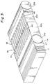
- FIG. 1A shows a processing tank 9 having a processing path length adjusting mechanism 11.
- Processing tank 9 can be for any of the processing steps of a processor as previously discussed.
- processing tank 9 can be of a rack and tank arrangement as described in, for example, GB Patent No. 559027, the subject matter of which is herein incorporated by reference.
- path length adjusting mechanism 11 can also be applied to a variety of other types of processing tanks.
- a rack 15 can be easily inserted and removed from a tank 17, to form a low volume photosensitive material processing vessel.
- Processing path 21 includes a downward portion 21', a turnaround portion 21'' and an upward portion 21'''.
- Rack 15 includes a plurality of rollers 23a-23d as illustrated in the figure, while tank 17 includes nozzle openings 25a-25g and 25a'-25g' which supply processing solution to tank 17.
- the number of drive rollers and nozzle openings are illustrated as an example, and it recognized that the number of drive rollers and nozzles used are based on design considerations.
- rack 15 in addition to drive rollers 23a-23d, rack 15 includes processing path length adjusting mechanism 11 which is operationally connected to and provided adjacent to lowermost drive roller 23a so as to define a space 21a. Space 21a forms a part of the processing path 21 therebetween which is turnaround portion 21''. As shown in Figure 1A, an upper surface 11a of processing path length adjustment mechanism 11 is curved to match the curvature of lowermost drive roller 23a to form the path of turnaround portion 21''.
- Tank 17 with rack 15 inserted therein includes an entrance 25 where the photosensitive material enters tank 17 and is conveyed by the drive rollers 23a-23d along downward portion 21' of path 21. While the photosensitive material is being conveyed, processing solution is supplied to the photosensitive material by way of nozzle openings 25a-25g and 25a'-25g'. As the photosensitive material is conveyed to the lowermost drive roller 23a, it is transported along turnaround portion 21'' between lowermost drive roller 23a and upper surface 11a of processing path length adjusting mechanism 11 to the upward portion 21''' of processing path 21, and finally to an exit 27.
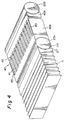
- processing path length adjusting mechanism 11 forms a normal processing path length. If a photoprocessing operation in which a shortened processing path length is sufficient, then processing path length adjusting mechanism 11 can be moved or expanded to the position shown in Figure 2A. As illustrated in the embodiment of Figures 1A and 2A, processing path length adjusting mechanism 11 can be a flexible member or bellows which is moved or expanded so as to block at least the lower nozzle openings 25f, 25g, 25f', 25g' and move turnaround portion 21'' upward. This provides for a shortened processing path length as illustrated in Figure 2A. With the shortened processing path length, during processing, the photosensitive material enters and exits processing tank 17 in the same manner as described with reference to Figure 1A, however, since the path length adjusting mechanism 11 has been moved or expanded, the processing path length is shortened.
- Figure 2A illustrates the positioning of path length adjusting mechanism 11 to one point in which the lower nozzle openings 25f,25g,25f',25g' are blocked. It is recognized that processing path length adjusting mechanism 11 can be moved or expanded to a plurality of positions depending on the length of the desired processing path. For example, it is recognized that processing path length adjusting mechanism 11 could be moved or expanded upwardly so as to block further nozzle openings and provide for an even shorter processing path length. It is further recognized that processing path length adjusting mechanism 11 can be moved or expanded an amount which is less than what is illustrated in Figure 2A so as to keep the lower nozzle openings open but at the same time provide for a shorter processing path length.
- the present invention can include an intermediate spacer member 40 in the spacing between rollers 23a and 23b.
- Intermediate spacer member 40 is illustrated in detail in Figures 3 and 4 and comprises a first member 40a having a plurality of spaced teeth-like members 41 and a second member 40b having a plurality of spaced teeth-like members 43.
- path length adjusting mechanism 11 can be in the form of an expandable flexible member or bellows.
- Path length adjusting mechanism 11 can be operationally connected to the lowermost drive roller 23a, such that a movement or expansion of path length adjusting mechanism 11 from the position illustrated in Figure 1A to the position illustrated in Figure 2A will cause a corresponding movement of drive roller 23a; while maintaining spacing 21a between drive roller 23a and surface 11a of path length adjusting mechanism 11 which defines turnaround portion 21''.
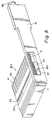
- Figure 1B illustrates the position of path length adjusting mechanism 11 which corresponds to the position illustrated in Figure 1A.
- the apparatus of the present invention can include a gearing arrangement which comprises at least one screw or worm gear 31 positioned at a side of tank 17.
- screw gear 31 can be inserted next to a drive gear arrangement 100 which is utilized to drive rollers 23a-23d.
- screw gear 31 can engage with a rack gear 33 having a hole 33'.
- a shaft 33a onto which the roller 23a is mounted extends through hole 33' of rack gear 33.
- Screw gear 31 includes an extension part 37 which extends above rack 15 and ends in a handle 15a.
- the rack gear 33 is operationally associated with the shaft of the drive roller 23a, path length adjusting mechanism 11 and first member 40a such that a turning of handle 15a will cause a rotation of screw gear 31 engaged with rack gear 33 so as to move drive roller 33a and correspondingly move first member 40a and path length adjusting mechanism 11 to the position illustrated in Figures 2A and 2B and vice versa.
- alternative arrangements such as a pneumatic assembly or a different type of gear arrangement can be used instead of the disclosed screw and rack gear to achieve the described movement.
- each of teeth-like members 41 and 43 are insertable into corresponding spaces 45 created by the teeth-like members 41 and 43 of each of the first and second members 40a and 40b. In the position illustrated in Figures 1A and 1B, teeth-like members 41 and 43 are not deeply inserted into spaces 45.
- first member 40a and drive roller 23a are moved to the position illustrated in Figures 2A and 2B, the bellows are expanded and the teeth-like members 41,43 are inserted into corresponding spaces 45.
- intermediate spacing member 40 maintains the proper spacing for processing path 21 and at the same time, minimizes the internal volume of tank 17 so as to require less processing solution.
- intermediate spacing member 40 is not limited to the disclosed configuration. It is noted that a collapsible flexible member which collapses upon the upward movement of path length adjusting member 11 can be used as an intermediate spacing member.
- processing path length adjusting mechanism 11 is shown as an expandable bellows. This is only one example and it is recognized that any movable, flexible or expandable member can be utilized as processing path length adjusting mechanism 11.
- a piston and cylinder arrangement can be provided such that the piston is operationally connected to roller 23a and intermediate spacer member 40 and includes a curvature to define turnaround portion 21''. Movement of the piston can be achieved in a known manner by using a pneumatic cylinder which can be, for example, mounted on the tank.
- Figures 6A and 6B are perspective drawings of textured fluid-bearing surfaces 200 and 205 which can be located on one or both surfaces of processing path 21.
- Textured surfaces 200 and 205 are textured by any known process, e.g., knurling, molded, EDM electro-discharged machined or applied.
- Knurls 202 or 206 are respectively shown on surfaces 200 and 205.
- the texturing ( Figures 6A,6B) and cantering ( Figure 6A) improve the flow of processing solution between the photosensitive material and the one or both surfaces of processing path 21, and prevent the photosensitive material from sticking on the surfaces.
- control mechanism 50 can include a computer or a central processing unit which is operationally connected to screw drive gear 31 by way of line 53.
- a plurality of desired predetermined lengths of the processing path can be inputted into the control mechanism 50. Therefore, if the user knows of the specific type of processing to be performed, he could input the desired processing path length into control mechanism 50 which is used for that particular type of photoprocessing.
- Control mechanism 50 can automatically actuate screw drive gear 31 to move path length adjusting mechanism 11 to the designated position along tank 17 so as to provide for the particular predetermined length of the processing path.
Landscapes
- Physics & Mathematics (AREA)
- General Physics & Mathematics (AREA)
- Photographic Processing Devices Using Wet Methods (AREA)
Applications Claiming Priority (2)
| Application Number | Priority Date | Filing Date | Title |
|---|---|---|---|
| US947687 | 1997-10-09 | ||
| US08/947,687 US5864729A (en) | 1997-10-09 | 1997-10-09 | Process tank having an adjustable processing path length and method of adjusting the same |
Publications (2)
| Publication Number | Publication Date |
|---|---|
| EP0908772A2 true EP0908772A2 (de) | 1999-04-14 |
| EP0908772A3 EP0908772A3 (de) | 1999-08-18 |
Family
ID=25486582
Family Applications (1)
| Application Number | Title | Priority Date | Filing Date |
|---|---|---|---|
| EP98203253A Withdrawn EP0908772A3 (de) | 1997-10-09 | 1998-09-28 | Behandlungsbehälter mit einer verstellbare Behandlungsweglänge und Verfahren dazu |
Country Status (4)
| Country | Link |
|---|---|
| US (1) | US5864729A (de) |
| EP (1) | EP0908772A3 (de) |
| JP (1) | JPH11194470A (de) |
| CN (1) | CN1214463A (de) |
Families Citing this family (3)
| Publication number | Priority date | Publication date | Assignee | Title |
|---|---|---|---|---|
| US6520694B1 (en) | 2002-01-18 | 2003-02-18 | Eastman Kodak Company | System and method for processing photographic film images |
| US6666592B1 (en) | 2002-09-20 | 2003-12-23 | Eastman Kodak Company | Photographic processing system |
| US6761491B2 (en) * | 2002-12-09 | 2004-07-13 | Eastman Kodak Company | Photographic processor and supply cartridge with an information exchange arrangement |
Family Cites Families (10)
| Publication number | Priority date | Publication date | Assignee | Title |
|---|---|---|---|---|
| US2133109A (en) * | 1936-07-28 | 1938-10-11 | Warner Bros | Motion picture film guiding apparatus |
| US2169061A (en) * | 1938-05-02 | 1939-08-08 | Warner Bros | Continuous-film-treating apparatus |
| DE1066093B (de) * | 1956-12-27 | 1959-09-24 | Williamson Manufacturing Company Limited, London | Gerät zum Behandeln von band- oder fadenförmigem Gut, insbesondere von Filmbändern in fortlaufendem Betrieb |
| IT1007072B (it) * | 1974-01-24 | 1976-10-30 | Falomo Lodovico | Apparecchiatura per il trasporto di materiale in foglio entro vasche di trattamento |
| DE3717910A1 (de) * | 1986-05-29 | 1987-12-03 | Noritsu Kenkyu Center Co | Filmtransporteinheit zur verwendung bei einer automatischen filmentwicklungsmaschine |
| DE3833733A1 (de) * | 1988-10-04 | 1990-04-05 | Agfa Gevaert Ag | Verfahren und vorrichtung zur koppelung von verschiedenartigen maschinen zur verarbeitung von bandfoermigen, lichtempfindlichen fotografischen materialien |
| US4975723A (en) * | 1990-02-02 | 1990-12-04 | Gretag Systems, Inc. | Paper-processing control apparatus |
| US5311235A (en) * | 1992-03-02 | 1994-05-10 | Eastman Kodak Company | Driving mechanism for a photographic processing apparatus |
| JP2845151B2 (ja) * | 1995-02-16 | 1999-01-13 | ノーリツ鋼機株式会社 | 写真感光材料現像装置 |
| GB9603679D0 (en) * | 1996-02-21 | 1996-04-17 | Kodak Ltd | Improvements in or relating to photographic processing apparatus |
-
1997
- 1997-10-09 US US08/947,687 patent/US5864729A/en not_active Expired - Fee Related
-
1998
- 1998-09-28 EP EP98203253A patent/EP0908772A3/de not_active Withdrawn
- 1998-10-08 JP JP10286787A patent/JPH11194470A/ja active Pending
- 1998-10-09 CN CN98120907A patent/CN1214463A/zh active Pending
Also Published As
| Publication number | Publication date |
|---|---|
| JPH11194470A (ja) | 1999-07-21 |
| US5864729A (en) | 1999-01-26 |
| CN1214463A (zh) | 1999-04-21 |
| EP0908772A3 (de) | 1999-08-18 |
Similar Documents
| Publication | Publication Date | Title |
|---|---|---|
| JP2587354B2 (ja) | 露光済かつ現像済写真フィルムの写真印画作成装置 | |
| JPH0138589Y2 (de) | ||
| KR100204426B1 (ko) | 가이드 폭 변경 방법 및 가이드 폭 변경 장치 | |
| US5864729A (en) | Process tank having an adjustable processing path length and method of adjusting the same | |
| US4837601A (en) | Automatic photographic paper processing apparatus | |
| DE69806877T2 (de) | Verfahren und Vorrichtung zur Positionierung eines Blattes von photoempfindlichen Material in einem photographischen Printer | |
| US5452043A (en) | Rack and a tank for a photographic low volume thin tank insert for a rack and a tank photographic processing apparatus | |
| JP3170954B2 (ja) | 感光材料の現像処理方法及び装置 | |
| US4583838A (en) | Printing apparatus | |
| EP0909984B1 (de) | Verarbeitung von photographischem Material | |
| JP2700472B2 (ja) | 写真感光材料の処理機 | |
| US5761563A (en) | Photographic processing apparatus | |
| EP0649058A1 (de) | Fotografischer Flüssigkeitsbehandlungsapparat | |
| US5606720A (en) | Photographic processing apparatus | |
| US5461449A (en) | Method and means for separating leader from film in photographic processing machine | |
| US6035167A (en) | Wet-type image forming apparatus and squeezing method | |
| US5452041A (en) | Apparatus for processing photographic sheet material | |
| US6203219B1 (en) | Photosensitive material processing apparatus | |
| JPH028279Y2 (de) | ||
| US5911091A (en) | Method and apparatus for processing photosensitive materials | |
| US5842073A (en) | Photographic processing apparatus | |
| JPS62232651A (ja) | 感光材料処理装置 | |
| US6435741B1 (en) | Processing photographic material | |
| JPS63259662A (ja) | 写真現像装置 | |
| JP3364330B2 (ja) | 感光材料処理装置のラック構造 |
Legal Events
| Date | Code | Title | Description |
|---|---|---|---|
| PUAI | Public reference made under article 153(3) epc to a published international application that has entered the european phase |
Free format text: ORIGINAL CODE: 0009012 |
|
| AK | Designated contracting states |
Kind code of ref document: A2 Designated state(s): CH DE FR GB IT LI |
|
| AX | Request for extension of the european patent |
Free format text: AL;LT;LV;MK;RO;SI |
|
| PUAL | Search report despatched |
Free format text: ORIGINAL CODE: 0009013 |
|
| AK | Designated contracting states |
Kind code of ref document: A3 Designated state(s): AT BE CH CY DE DK ES FI FR GB GR IE IT LI LU MC NL PT SE |
|
| AX | Request for extension of the european patent |
Free format text: AL;LT;LV;MK;RO;SI |
|
| 17P | Request for examination filed |
Effective date: 20000126 |
|
| AKX | Designation fees paid |
Free format text: CH DE FR GB IT LI |
|
| 17Q | First examination report despatched |
Effective date: 20031125 |
|
| STAA | Information on the status of an ep patent application or granted ep patent |
Free format text: STATUS: THE APPLICATION IS DEEMED TO BE WITHDRAWN |
|
| 18D | Application deemed to be withdrawn |
Effective date: 20040406 |