EP0908577A2 - Modular cladding system - Google Patents
Modular cladding system Download PDFInfo
- Publication number
- EP0908577A2 EP0908577A2 EP98118569A EP98118569A EP0908577A2 EP 0908577 A2 EP0908577 A2 EP 0908577A2 EP 98118569 A EP98118569 A EP 98118569A EP 98118569 A EP98118569 A EP 98118569A EP 0908577 A2 EP0908577 A2 EP 0908577A2
- Authority
- EP
- European Patent Office
- Prior art keywords
- fastening
- modular system
- carrier element
- viewing
- plug
- Prior art date
- Legal status (The legal status is an assumption and is not a legal conclusion. Google has not performed a legal analysis and makes no representation as to the accuracy of the status listed.)
- Withdrawn
Links
Images

Classifications
-
- E—FIXED CONSTRUCTIONS
- E04—BUILDING
- E04F—FINISHING WORK ON BUILDINGS, e.g. STAIRS, FLOORS
- E04F13/00—Coverings or linings, e.g. for walls or ceilings
- E04F13/07—Coverings or linings, e.g. for walls or ceilings composed of covering or lining elements; Sub-structures therefor; Fastening means therefor
- E04F13/08—Coverings or linings, e.g. for walls or ceilings composed of covering or lining elements; Sub-structures therefor; Fastening means therefor composed of a plurality of similar covering or lining elements
- E04F13/0801—Separate fastening elements
- E04F13/0803—Separate fastening elements with load-supporting elongated furring elements between wall and covering elements
- E04F13/081—Separate fastening elements with load-supporting elongated furring elements between wall and covering elements with additional fastening elements between furring elements and covering elements
- E04F13/0812—Separate fastening elements with load-supporting elongated furring elements between wall and covering elements with additional fastening elements between furring elements and covering elements fixed by means of spring action
Definitions
- the invention relates to a modular system for covering surfaces and to build functional surfaces and functional walls, the several Viewing elements and support elements for fastening the viewing elements includes on a mounting surface.
- a component is from the German utility model 295 01 954.9 known for covering surfaces with surface elements, in which a plate-like carrier base element is provided which has at least one Has surface element and detachable with both to be clad Surface as well as connected with complementary base elements is.
- the surface elements can either on the carrier base element be fixed or releasably attached, and the basic carrier elements themselves are provided with grooves and tongues, which make a coupling adjacent Allow basic carrier elements.
- the surface elements of which, for example consist of tiles, wood, marble, metal or ceramic elements can, wall coverings, especially in wet rooms, created unlike conventional tiling with less time can be created, are particularly good for renovation purposes suitable and, if necessary, simply removed or modified can be.
- the modular system has several viewing elements has, which are provided on the back with fasteners, that do not protrude beyond the outer contour of the viewing elements.
- the visual elements according to the invention - similar to this conventional tiles is the case - basically from above towards the Place the covering surface without any fastenings protruding from the side.
- a joint strip which according to the invention is a separate one, serves for viewing elements Component is formed and thus subsequently between adjacent Visible elements can be used.
- the at least one fastening zone for a fastener which has the carrier element connects to the mounting surface.
- the carrier element can be rail-like be trained. This has the advantage that on a carrier element a variety of viewing elements can be attached, and that the carrier element according to the external circumstances on each desired length can be cut to length. At the same time, the carrier element Manufacture in a material-saving way, since the visible elements do not completely covered.
- the carrier element lies in the fastening zone essentially flat on the fastening surface on, the attachment zone through a thin-walled Area of the support element can be formed. This results on the one hand stable attachment of the fastener to the mounting surface.
- fasteners for example Attach staples easily in the mounting area as this is thin-walled.
- the carrier element for fastening the visible elements to the fastening surface two differently designed fastenings, preferably a snap fastening and a push-in fixture.
- This embodiment is a very universal modular system created in which the viewing elements First plugged in on one side and then on the other side can be locked. Such attachment allows extremely time-saving installation, since after inserting the viewing element Alignment has already been made in the plug connection, that the locking connection is then made without further alignment can be. Compared to embodiments where only Plug connections are available, this will save a considerable amount of time achieved during assembly because the assembly process starts of the viewing element on the plug connection thus comprises the viewing element is fully aligned and only needs to be locked.
- the plug-in fastening can advantageously comprise a projection, that engages behind the visual element or a part of the visual element can be.
- the latching attachment can, for example, by a Arrowhead profile be formed, on which a correspondingly complementary trained area of the viewing element is snapped on.
- Carrier element is resilient in one area.
- the carrier element when inserting the joint strip, i.e. after installing the visible elements in the direction of the mounting surface can be deformed to fully attach the mounting strip to snap the mounting bracket into place.
- the joint strip which is preferably T-shaped in cross section, by Apply pressure into the mounting receptacle, where at the same time the carrier element is elastic due to the pressure exerted yields in the direction of the mounting surface, so that the joint strip is fully inserted into the mounting bracket. Then moved the carrier element resiliently in the direction of the ßefest Trentsthesis away, so that the viewing elements with light pressure on the Joint strips are in contact or the joint strips with slight pressure on the Visual elements are present.
- a carrier element when the carrier element is seen in cross section is particularly advantageous on one side a snap fastening and on the opposite Side has a plug-in attachment, with at least in between a fastening zone and the receptacle for the joint strip are provided is.
- Such a carrier element can save material and is inexpensive are compact and easy to assemble.
- a carrier element can advantageously be extruded Manufacture component, for example as a profile rail.
- the carrier element can have a hollow profile area have, which is preferably designed as a support area for the viewing element is.
- a hollow profile area enables lateral insertion of other connecting elements, for example a corner or Cross connection and at the same time creates a stabilization of the fastening the view elements, as an additional contact surface or a Support area for the visual elements is created.
- the fasteners can, for example, on the viewing elements be fixed by gluing. However, it is also a one-piece training the view elements and the fastening elements possible.
- the fastening means a snap fastening and has a plug-in fastening, since in this case the viewing element for Assembly does not have to be rotated, but on both sides with both the corresponding latching or plug-in fastening of the carrier element can engage.
- the fastener rail-like and preferably extruded since this is an inexpensive Manufacturing and cutting to any desired length enables.
- a crossing element be provided, which has at least one pin, which is complementary is formed to a hollow profile area of the carrier element.
- Such an intersection element can serve several support elements and / or several joint strips with one another at T- or X-shaped crossing points connect to.
- the crossing element between two Fastening shots have a rounded corner, preferably on the a fastening clip for a view cover is arranged. This allows corner areas to be designed to be visually appealing, whereby the view cover through the fastening clip provided on the crossing element only has to be plugged on and locked.
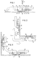
- Fig. 1 shows a first embodiment of a modular system for Creation or covering of wall, ceiling and / or floor surfaces as well as for the construction of functional surfaces and functional walls a plurality of viewing elements 10, 12, which are on their back, i.e. on their side opposite the visible side, with fastening means 18, 20 are provided. These fasteners are not over the outer contour the viewing elements 10, 12 in front, but are arranged on the back.
- FIG. 1 there is a fastening means on the underside of the viewing element 10 18 glued, which is rail-like and one Cross section forms, which has a latching opening 22 with a conical inlet 23 and forms a projection 24 that leads to the rear of the viewing element 10 creates a free space 26.
- the fastening means 18 is thus in cross section seen C-shaped, with a side of one leg of the C Tab 24 connects.
- the viewing element 10 is plate-shaped formed and has a chamfer 28 in the region of its edges on.
- the viewing element 12 is a lateral closure element trained and therefore has a substantially L-shaped Cross-section, the short leg of the L to a side closure an attachment surface 30 forms.
- the fastening of the viewing elements 10, 12 on the fastening surface 30 takes place with the aid of a carrier element 32, which is rail-like as an extrusion part is trained.
- the carrier element 32 is seen in cross section on its one side (on the left in FIG. 1), a snap fastening 34 in Shape of an arrowhead profile and on the opposite (in Fig. 1 right) side a plug-in fastener 36 in the form of an integrally formed, L-shaped Leg or an S-shaped profile section, with between the leg 36, which forms a projection, and the fastening surface 30 a space is created in which the projection 24 of the Fastening means 18 is inserted.
- the carrier element is first 32 cut to the desired length and then by means of a stapling device on the fastening surface, for example one Plasterboard wall, attached by staples 40 through the support member 32 driven into the mounting surface 32.
- a stapling device on the fastening surface, for example one Plasterboard wall
- the stapler can be advantageous in the area of the strip Attachment zone 38 are set and operated.
- the viewing element 12 with the fastening means 20 on the snap fastening 34 of the carrier element 32 are plugged on.
- the viewing element 10 is with the projection 24 of the fastener 18 in the plug-in fastening 36 of the support element 32 hooked and then in the direction the mounting surface 30 pressed.
- the (not shown) Fastening means 18 on the opposite side of the Viewing element 10 in a snap fastening of a further carrier element on.
- the joint strip 44 can then be used to seal the intermediate space between the two adjacent viewing elements 10, 12 be inserted into the mounting receptacle 42 of the support member 32.
- the viewing element 10 in the direction of the mounting surface 30 can be moved slightly because the carrier element 32 in one area 46 is resilient. This allows the joint strip 44 to be complete are locked in the mounting receptacle 42, whereupon the Viewing element 10 springs back slightly and seals on the joint strip is present.
- Fig. 2 shows an outer corner area of the system of Fig. 1, wherein as Transition element, a viewing element 14 is provided, which has an outer corner covered.
- the viewing element 14 is L-shaped in cross section and has a molded locking opening 20 and a molded Projection 21, which is formed by an L-shaped leg.
- the viewing element 14 only with the projection 21 in the Plug-in fastening 36 of the associated carrier element 32 is inserted and then pressed with the latch opening 20 onto the latch fastening 34 be, whereby the conical tip of the latch 34 in the Locking opening 20 engages.
- FIG. 3 finally shows an inner corner area of the modular system of FIG 1 and 2, in which a viewing element 16 for cladding the corner area is trained.
- a viewing element 16 for cladding the corner area is trained.
- the Projection 21 of the viewing element 16 in the plug-in fastening 36 of the in FIG. 3 left-hand support member 32 are inserted, whereupon the viewing element 16 by pivoting with its latching opening 20 in the latching attachment 34 of the carrier element arranged on the right in FIG. 3 32 can be locked.
- FIGS. 1 to 3 are provided with the same reference numerals.
- the modular system shown in FIGS. 4 and 5 has a carrier element 32 ', which is functionally similar to the carrier element 32 of FIG. 1 to 3 is constructed.
- the support element 32 ' is the plug-in fastening 36 'as a profile with a stretched and inverse cross section Z-shaped, being on the underside of parallel to the mounting surface 30 'extending leg provided a locking toothing is. Due to the selected cross-sectional shape, the carrier element 32 'is in one Area 46 'designed to be resilient.
- the mounting receptacle 42 'for the joint strip 44' is similar to formed by two parallel profiles in the first embodiment. Likewise, the latching attachment 34 'of the carrier element 32' engages in one Locking opening 20 'of the fastener 18' which on the underside of the Viewing element 10 'is attached.
- the carrier element 32 ' has a cross section Hollow profile area 48 ', which has a trapezoidal cross section and is designed as a support area for the viewing element 10 '.
- the dimension of the hollow profile area 48 ' is selected such that the viewing element 10 'with proper fastening on the flat top of the hollow profile area 48 '.
- FIG. 5 shows a perspective view of four at right angles to one another extending support elements 36 'which on a fastening surface 30' are fastened by staples 40 '.
- Carrier elements 32 ' are formed as extruded flat rails.
- Crossing element 50 ' is provided, which is square and has a plate-like body.
- a pin 52 ', 54' is provided on each side of the crossing element 50 ', the pin 52 'complementary to the hollow profile area 48' trained and inserted into this.
- the pin 54 ' is also on the crossing element 50 'molded and positioned so that this one Alignment aid for the vertically downwardly extending support element 32 ' forms.
- a total of four fastening receptacles are centered on the intersection element 50 ' 56 'provided, in each of which a joint strip 44' is inserted can be.
- this can Crossing element 50 'between two fastening receptacles 56' have a rounded corner, on which preferably a fastening clip is arranged for a view cover.
- a Fastening cover which has the shape of a quarter circle, be plugged onto the crossing element 50 'from above, whereby a attractive corner finish is given.
- FIG Fig. 5 The attachment of the viewing elements 10 'to the carrier elements 32' is shown in FIG Fig. 5 not shown.
- the visual elements 10 'initially only with the projection 24' of the fastening means 18 ' inserted behind the plug fastening 36 'of the carrier element 32' must be and then with the opposite fastener 18 'into the snap fastening 34' of a further carrier element 32 'must be locked.
- the resilient area 46 ' of the carrier element 32 ' when inserting the joint strip 44' easily after, whereby a secure seal between the viewing elements 10 ' and the joint strip 44 'is guaranteed.
- the carrier element according to the invention With the carrier element according to the invention, the Controlled the accuracy of the space between the surface elements, since the fasteners are placed close to the edge and around spaced an exact distance parallel to the edge of the viewing elements are. In practice, this represents a significant advantage because of the accuracy of the overall system is determined solely by those components which have been produced in the manufacturing facility and which are manufactured by corresponding requirements can be met exactly. This is an inaccuracy during installation is almost impossible.
- Carrier elements or visible elements can be used that are similar trained fasteners, for example arrowhead profiles have to edge edging, edge edging or the like form.
Abstract
Description
Die Erfindung betrifft ein modulares System zur Verkleidung von Flächen und zum Aufbau von Funktionsflächen und Funktionswänden, das mehrere Sichtelemente sowie Trägerelemente zur Befestigung der Sichtelemente an einer Befestigungsfläche umfaßt.The invention relates to a modular system for covering surfaces and to build functional surfaces and functional walls, the several Viewing elements and support elements for fastening the viewing elements includes on a mounting surface.
Aus dem deutschen Gebrauchsmuster 295 01 954.9 ist ein Bauelement zur Verkleidung von Flächen mit Oberflächenelementen bekannt, bei dem ein plattenartiges Trägergrundelement vorgesehen ist, das mindestens ein Oberflächenelement aufweist und lösbar sowohl mit der zu verkleidenden Fläche als auch mit komplementären Trägergrundelementen verbunden ist. Die Oberflächenelemente können auf dem Trägergrundelement entweder fest oder lösbar angebracht sein, und die Trägergrundelemente selbst sind mit Nuten und Federn versehen, die eine Kopplung aneinandergrenzender Trägergrundelemente ermöglichen.A component is from the German utility model 295 01 954.9 known for covering surfaces with surface elements, in which a plate-like carrier base element is provided which has at least one Has surface element and detachable with both to be clad Surface as well as connected with complementary base elements is. The surface elements can either on the carrier base element be fixed or releasably attached, and the basic carrier elements themselves are provided with grooves and tongues, which make a coupling adjacent Allow basic carrier elements.
Mittels derartiger Bauelemente, deren Oberflächenelemente beispielsweise aus Fliesen, Holz-, Marmor-, Metall- oder Keramikelementen bestehen können, können Wandverkleidungen, insbesondere in Naßräumen, geschaffen werden, die im Gegensatz zu konventionellen Verfliesungen mit geringerem Zeitaufwand erstellbar sind, sich besonders gut für Renovierungszwecke eignen und ggf. auch wieder einfach entfernt oder modifiziert werden können. By means of such components, the surface elements of which, for example consist of tiles, wood, marble, metal or ceramic elements can, wall coverings, especially in wet rooms, created unlike conventional tiling with less time can be created, are particularly good for renovation purposes suitable and, if necessary, simply removed or modified can be.
Es ist das der Erfindung zugrundeliegende Problem (Aufgabe), ein modulares System der eingangs angegebenen Art zu schaffen, das unter Beibehaltung der Vorteile des bekannten Verkleidungssystems eine vereinfachte Herstellung der Bauelemente sowie eine Vereinfachung der Verarbeitung und Montage erbringt.It is the problem (task) underlying the invention, a modular one To create the system of the type specified, while maintaining a simplified of the advantages of the known cladding system Manufacture of the components and simplification of processing and assembly.
Die Lösung dieser Aufgabe erfolgt durch die Merkmale des Anspruchs 1 und insbesondere dadurch, das modulare System mehrere Sichtelemente aufweist, die an ihrer Rückseite mit Befestigungsmitteln versehen sind, die nicht über die Außenkontur der Sichtelemente vorstehen. Hierdurch lassen sich die erfindungsgemäßen Sichtelemente - ähnlich wie dies bei herkömmlichen Fliesen der Fall ist - grundsätzlich von oben auf die zu verkleidende Fläche ohne seitlich vorstehende Befestigungsmittel aufsetzen. Zur Abdichtung des Zwischenraumes zwischen zwei benachbarten Sichtelementen dient ein Fugenstreifen, der erfindungsgemäß als separates Bauteil ausgebildet ist und somit nachträglich zwischen benachbarte Sichtelemente eingesetzt werden kann. Zur Befestigung der Sichtelemente und des Fugenstreifens dient ein Trägerelement, das zumindest eine Befestigungszone für ein Befestigungsmittel aufweist, welches das Trägerelement mit der Befestigungsfläche verbindet.This object is achieved by the features of claim 1 and in particular, the modular system has several viewing elements has, which are provided on the back with fasteners, that do not protrude beyond the outer contour of the viewing elements. Hereby the visual elements according to the invention - similar to this conventional tiles is the case - basically from above towards the Place the covering surface without any fastenings protruding from the side. To seal the space between two neighboring ones A joint strip, which according to the invention is a separate one, serves for viewing elements Component is formed and thus subsequently between adjacent Visible elements can be used. For fastening the viewing elements and the joint strip serves a carrier element, the at least one fastening zone for a fastener which has the carrier element connects to the mounting surface.
Erfindungsgemäß ist somit an dem Trägerelement eine spezielle Befestigungszone vorgesehen, die von dem Montagepersonal ohne weiteres erkannt und bestimmungsgemäß verwendet werden kann. Schließlich ist in dem Trägerelement eine Befestigungsaufnahme für den Fugenstreifen vorgesehen. Hierdurch ist ein modulares System geschaffen, dessen Trägerelement sowohl zur Befestigung der Sichtelemente wie auch zur Aufnahme des Fugenstreifens dient, der nach Montage der Sichtelemente in das Trägerelement eingesteckt werden kann, so daß im Bereich der Fuge eine gute Abdichtung gewährleistet ist.According to the invention there is therefore a special fastening zone on the carrier element provided that easily recognized by the assembly staff and can be used as intended. Finally in the mounting element is provided with a fastening receptacle for the joint strip. This creates a modular system, the support element for fastening the viewing elements as well as for mounting of the joint strip, which is used after mounting the viewing elements in the support element can be inserted so that in the area of the joint good sealing is guaranteed.
Vorteilhafte Ausführungsformen der Erfindung sind in der Beschreibung, den Zeichnungen sowie den Unteransprüchen beschrieben.Advantageous embodiments of the invention are in the description, the drawings and the subclaims.
Nach einer ersten Ausführungsform kann das Trägerelement schienenartig ausgebildet sein. Hierdurch ergibt sich der Vorteil, daß an einem Trägerelement eine Vielzahl von Sichtelementen befestigt werden kann, und daß das Trägerelement entsprechend den äußeren Gegebenheiten auf jede gewünschte Länge abgelängt werden kann. Gleichzeitig läßt sich das Trägerelement materialsparend herstellen, da dieses die Sichtelemente nicht ganzflächig überdeckt.According to a first embodiment, the carrier element can be rail-like be trained. This has the advantage that on a carrier element a variety of viewing elements can be attached, and that the carrier element according to the external circumstances on each desired length can be cut to length. At the same time, the carrier element Manufacture in a material-saving way, since the visible elements do not completely covered.
Nach einer weiteren Ausführungsform der Erfindung liegt das Trägerelement in der Befestigungszone im wesentlichen flächig auf der Befestigungsfläche auf, wobei die Befestiungszone durch einen dünnwandigen Bereich des Trägerelementes gebildet sein kann. Hierdurch ergibt sich einerseits eine stabile Anlage des Befestigungselementes an der Befestigungsfläche. Andererseits lassen sich Befestigungsmittel, beispielsweise Heftklammern problemlos in der Befestigungszone anbringen, da diese dünnwandig ausgebildet ist.According to a further embodiment of the invention, the carrier element lies in the fastening zone essentially flat on the fastening surface on, the attachment zone through a thin-walled Area of the support element can be formed. This results on the one hand stable attachment of the fastener to the mounting surface. On the other hand, fasteners, for example Attach staples easily in the mounting area as this is thin-walled.
Nach einer weiteren vorteilhaften Ausführungsform weist das Trägerelement zur Befestigung der Sichtelemente an der Befestigungsfläche zwei unterschiedlich gestaltete Befestigungen auf, vorzugsweise eine Rastbefestigung und eine Steckbefestigung. Durch diese Ausführungsform ist ein sehr universelles modulares System geschaffen, bei dem die Sichtelemente an ihrer einen Seite zunächst eingesteckt und an ihrer anderen Seite anschließend verrastet werden können. Eine derartige Befestigung ermöglicht eine äußerst zeitsparende Montage, da nach Einstecken des Sichtelementes in die Steckverbindung bereits eine Ausrichtung so erfolgt ist, daß anschließend die Rastverbindung ohne weiteres Ausrichten hergestellt werden kann. Verglichen zu Ausführungsformen, bei denen lediglich Steckverbindungen vorhanden sind, wird hierdurch eine erhebliche Zeitersparnis bei der Montage erzielt, da der Montagevorgang ein Ansetzen des Sichtelementes an der Steckverbindung umfaßt wodurch das Sichtelement vollständig ausgerichtet ist und nur noch verrastet werden muß. Die Steckbefestigung kann auf vorteilhafte Weise einen Vorsprung umfassen, der von dem Sichtelement oder einem Teil des Sichtelementes hintergriffen werden kann. Die Rastbefestigung kann beispielsweise durch ein Pfeilspitzenprofil gebildet sein, auf das ein entsprechend komplementär ausgebildeter Bereich des Sichtelementes aufgerastet wird.According to a further advantageous embodiment, the carrier element for fastening the visible elements to the fastening surface two differently designed fastenings, preferably a snap fastening and a push-in fixture. This embodiment is a very universal modular system created in which the viewing elements First plugged in on one side and then on the other side can be locked. Such attachment allows extremely time-saving installation, since after inserting the viewing element Alignment has already been made in the plug connection, that the locking connection is then made without further alignment can be. Compared to embodiments where only Plug connections are available, this will save a considerable amount of time achieved during assembly because the assembly process starts of the viewing element on the plug connection thus comprises the viewing element is fully aligned and only needs to be locked. The plug-in fastening can advantageously comprise a projection, that engages behind the visual element or a part of the visual element can be. The latching attachment can, for example, by a Arrowhead profile be formed, on which a correspondingly complementary trained area of the viewing element is snapped on.
Nach einer weiteren vorteilhaften Ausführungsform der Erfindung ist das Trägerelement in einem Bereich federnd ausgebildet. Hierdurch ergibt sich der Vorteil, daß das Trägerelement bei Einsetzen des Fugenstreifens, d.h. nach der Montage der Sichtelemente etwas in Richtung der Befestigungsfläche deformiert werden kann, um den Befestigungsstreifen vollständig in der Befestigungsaufnahme einrasten zu lassen. Hierzu kann der Fugenstreifen, der vorzugsweise im Querschnitt T-förmig ausgebildet ist, durch Ausüben von Druck in die Befestigungsaufnahme eingesetzt werden, wobei gleichzeitig das Trägerelement durch den ausgeübten Druck elastisch in Richtung der Befestigungsfläche nachgibt, so daß der Fugenstreifen vollständig in der Befestigungsaufnahme eingeführt ist. Anschließend bewegt sich das Trägerelement wieder elastisch in Richtung von der ßefestigungsfläche weg, so daß die Sichtelemente mit leichtem Druck an dem Fugenstreifen anliegen bzw. der Fugenstreifen mit leichtem Druck an den Sichtelementen anliegt.According to a further advantageous embodiment of the invention Carrier element is resilient in one area. This results in the advantage that the carrier element when inserting the joint strip, i.e. after installing the visible elements in the direction of the mounting surface can be deformed to fully attach the mounting strip to snap the mounting bracket into place. For this, the joint strip, which is preferably T-shaped in cross section, by Apply pressure into the mounting receptacle, where at the same time the carrier element is elastic due to the pressure exerted yields in the direction of the mounting surface, so that the joint strip is fully inserted into the mounting bracket. Then moved the carrier element resiliently in the direction of the ßefestigungsfläche away, so that the viewing elements with light pressure on the Joint strips are in contact or the joint strips with slight pressure on the Visual elements are present.
Besonders vorteilhaft ist es, wenn das Trägerelement im Querschnitt gesehen an seiner einen Seite eine Rastbefestigung und an der gegenüberliegenden Seite eine Steckbefestigung aufweist, wobei dazwischen mindestens eine Befestigungszone und die Aufnahme für den Fugenstreifen vorgesehen ist. Ein derartiges Trägerelement kann materialsparend und kostengünstig hergestellt werden, ist kompakt und leicht montierbar. Insbesondere läßt sich ein solches Trägerelement auf vorteilhafte Weise als extrudiertes Bauteil, beispielsweise als eine Profilschiene herstellen.It when the carrier element is seen in cross section is particularly advantageous on one side a snap fastening and on the opposite Side has a plug-in attachment, with at least in between a fastening zone and the receptacle for the joint strip are provided is. Such a carrier element can save material and is inexpensive are compact and easy to assemble. Especially such a carrier element can advantageously be extruded Manufacture component, for example as a profile rail.
Das Trägerelement kann im Querschnitt gesehen einen Hohlprofilbereich aufweisen, der vorzugsweise als Stützbereich für das Sichtelement ausgebildet ist. Ein derartiger Hohlprofilbereich ermöglicht das seitliche Einstecken von weiteren Verbindungselementen, beispielsweise einer Eck- oder Kreuzverbindung und schafft gleichzeitig eine Stabilisierung der Befestigung der Sichtelemente, da eine zusätzliche Auflagefläche bzw. ein Stützbereich für die Sichtelemente geschaffen wird.Viewed in cross section, the carrier element can have a hollow profile area have, which is preferably designed as a support area for the viewing element is. Such a hollow profile area enables lateral insertion of other connecting elements, for example a corner or Cross connection and at the same time creates a stabilization of the fastening the view elements, as an additional contact surface or a Support area for the visual elements is created.
An den Sichtelementen können die Befestigungsmittel beispielsweise durch Verkleben befestigt sein. Es ist jedoch auch eine einstückige Ausbildung der Sichtelemente und der Befestigungselemente möglich. Hierbei ist es vorteilhaft, wenn das Befestigungsmittel eine Rastbefestigung und eine Steckbefestigung aufweist, da in diesem Fall das Sichtelement zur Montage nicht gedreht werden muß, sondern auf jeder Seite sowohl mit der korrespondierenden Rast- bzw. Steckbefestigung des Trägerelementes in Eingriff treten kann. Auch ist es vorteilhaft, das Befestigungsmittel schienenartig und vorzugsweise extrudiert auszubilden, da dies eine kostengünstige Herstellung und ein Ablängen auf jede gewünschte Länge ermöglicht.The fasteners can, for example, on the viewing elements be fixed by gluing. However, it is also a one-piece training the view elements and the fastening elements possible. Here it is advantageous if the fastening means a snap fastening and has a plug-in fastening, since in this case the viewing element for Assembly does not have to be rotated, but on both sides with both the corresponding latching or plug-in fastening of the carrier element can engage. It is also advantageous to use the fastener rail-like and preferably extruded, since this is an inexpensive Manufacturing and cutting to any desired length enables.
Nach einer weiteren Ausbildung der Erfindung kann ein Kreuzungselement vorgesehen sein, das zumindest einen Zapfen aufweist, der komplementär zu einem Hohlprofilbereich des Trägerelementes ausgebildet ist. Ein solches Kreuzungselement kann dazu dienen, mehrere Trägerelemente und/oder mehrere Fugenstreifen miteinander an T- oder X-förmigen Kreuzungspunkten zu verbinden. Um Eckbereiche innerhalb der Verkleidung günstig gestalten zu können, kann das Kreuzungselement zwischen zwei Befestigungsaufnahmen eine abgerundete Ecke aufweisen, an der vorzugsweise ein Befestigungsclip für eine Sichtabdeckung angeordnet ist. Hierdurch lassen sich Eckbereiche optisch ansprechend gestalten, wobei die Sichtabdeckung durch den am Kreuzungselement vorgesehenen Befestigungsclip lediglich aufgesteckt und verrastet werden muß.According to a further embodiment of the invention, a crossing element be provided, which has at least one pin, which is complementary is formed to a hollow profile area of the carrier element. Such an intersection element can serve several support elements and / or several joint strips with one another at T- or X-shaped crossing points connect to. Around corner areas within the cladding To be able to make cheap, the crossing element between two Fastening shots have a rounded corner, preferably on the a fastening clip for a view cover is arranged. This allows corner areas to be designed to be visually appealing, whereby the view cover through the fastening clip provided on the crossing element only has to be plugged on and locked.
Nachfolgend wird die vorliegende Erfindung rein beispielhaft anhand vorteilhafter Ausführungsformen und unter Bezugnahme auf die beigefügten Zeichnungen beschrieben. Es zeigen:
- Fig. 1
- eine Querschnittsansicht durch eine Ausführungsform eines modularen Systems, das auf einer ebenen Fläche montiert ist;
- Fig. 2
- eine Querschnittsansicht des modularen Systems von Fig. 1, das in einem Außeneckbereich montiert ist;
- Fig. 3
- eine Querschnittsansicht des modularen Systems von Fig. 1, das in einem Inneneckbereich montiert ist;
- Fig. 4
- eine Querschnittsansicht durch eine weitere Ausführungsform eines modularen Systems; und
- Fig. 5
- eine perspektivische Ansicht einer Kreuzungsverbindung des modularen Systems von Fig. 4.
- Fig. 1
- a cross-sectional view through an embodiment of a modular system, which is mounted on a flat surface;
- Fig. 2
- 1 is a cross-sectional view of the modular system of FIG. 1 mounted in an outside corner area;
- Fig. 3
- 1 is a cross-sectional view of the modular system of FIG. 1 mounted in an interior corner area;
- Fig. 4
- a cross-sectional view through a further embodiment of a modular system; and
- Fig. 5
- 4 shows a perspective view of an intersection connection of the modular system from FIG. 4.
Fig. 1 zeigt eine erste Ausführungsform eines modularen Systems zur
Schaffung oder Verkleidung von Wand-, Decken- und/oder Bodenflächen
sowie zum Aufbau von Funktionsflächen und Funktionswänden, das aus
mehreren Sichtelementen 10, 12 besteht, die an ihrer Rückseite, d.h. an
ihrer der Sichtseite gegenüberliegenden Seite, mit Befestigungsmitteln 18,
20 versehen sind. Diese Befestigungsmittel stehen nicht über die Außenkontur
der Sichtelemente 10, 12 vor, sondern sind an deren Rückseite angeordnet.Fig. 1 shows a first embodiment of a modular system for
Creation or covering of wall, ceiling and / or floor surfaces
as well as for the construction of functional surfaces and functional walls
a plurality of
Wie Fig. 1 zeigt, ist an der Unterseite des Sichtelementes 10 ein Befestigungsmittel
18 verklebt, das schienenartig ausgebildet ist und einen
Querschnitt bildet, der eine Rastöffnung 22 mit konischem Einlauf 23 sowie
einen Vorsprung 24 bildet, der zur Rückseite des Sichtelementes 10
einen Freiraum 26 schafft. Somit ist das Befestigungsmittel 18 im Querschnitt
gesehen C-förmig, wobei sich an einen Schenkel des C ein seitlicher
Vorsprung 24 anschließt. As shown in FIG. 1, there is a fastening means on the underside of the
Das an dem Sichtelement 12 angeformte Befestigungsmittel 20 weist demgegenüber
lediglich einen C-förmigen Querschnitt auf, der wiederum eine
Rastöffnung mit konischem Einlauf bildet. Das Sichtelement 10 ist plattenförmig
ausgebildet und weist im Bereich seiner Kanten eine Fase 28
auf. Das Sichtelement 12 ist demgegenüber als seitliches Abschlußelement
ausgebildet und besitzt daher einen im wesentlichen L-förmigen
Querschnitt, wobei der kurze Schenkel des L einen seitlichen Abschluß zu
einer Befestigungsfläche 30 bildet.The fastening means 20 formed on the
Die Befestigung der Sichtelemente 10, 12 an der Befestigungsfläche 30
erfolgt mit Hilfe eines Trägerelementes 32, das schienenartig als Extrusionsteil
ausgebildet ist. Das Trägerelement 32 weist im Querschnitt gesehen
an seiner einen (in Fig. 1 linken) Seite eine Rastbefestigung 34 in
Form eines Pfeilspitzenprofils und an der gegenüberliegenden (in Fig. 1
rechten) Seite eine Steckbefestigung 36 in Form eines angeformten, L-förmigen
Schenkels bzw. eines S-förmigen Profilabschnitts auf, wobei zwischen
dem Schenkel 36, der einen Vorsprung bildet, und der Befestigungsfläche
30 ein Freiraum geschaffen ist, in den der Vorsprung 24 des
Befestigungsmittels 18 eingesteckt ist.The fastening of the
Zwischen der Rastbefestigung 34 und der Steckbefestigung 36 weist das
Trägerelement eine Befestigungszone 38 für ein Befestigungsmittel 40 sowie
eine Befestigungsaufnahme 42 für einen Fugenstreifen 44 auf. Der
Fugenstreifen 44 besitzt im Querschnitt gesehen einen im wesentlichen
trapezförmigen Kopf sowie ein sich T-förmig daran anschließendes Befestigungsteil,
das mit Rastprofilen versehen ist, die in entsprechend komplementäre
Rastprofile in der Befestigungsaufnahme 42 eingreifen. Die
Befestigungsaufnahme 42 des Trägerelementes 32 ist durch zwei im wesentlichen
parallel zueinander verlaufende und senkrecht am Grundteil
des Trägerelementes 32 angeformte Profilschenkel gebildet.This has between the
Zur Montage des in Fig. 1 dargestellten Systems wird zunächst das Trägerelement
32 auf die gewünschte Länge abgelängt und anschließend
mittels einer Heftvorrichtung an der Befestigungsfläche, beispielsweise einer
Gipskartonwand, befestigt, indem Heftklammern 40 durch das Trägerelement
32 in die Befestigungsfläche 32 eingetrieben werden. Hierbei
kann das Heftgerät vorteilhaft im Bereich der streifenförmig verlaufenden
Befestigungszone 38 angesetzt und betätigt werden. Anschließend kann
das Sichtelement 12 mit dem Befestigungsmittel 20 auf die Rastbefestigung
34 des Trägerelementes 32 aufgesteckt werden. Das Sichtelement 10
wird mit dem Vorsprung 24 des Befestigungsmittels 18 in der Steckbefestigung
36 des Trägerelementes 32 eingehakt und anschließend in Richtung
der Befestigungsfläche 30 gedrückt. Hierdurch rastet das (nicht dargestellte)
Befestigungsmittel 18 an der gegenüberliegenden Seite des
Sichtelementes 10 in eine Rastbefestigung eines weiteren Trägerelementes
ein. Anschließend kann der Fugenstreifen 44 zur Abdichtung des Zwischenraumes
zwischen den beiden benachbarten Sichtelementen 10, 12
in die Befestigungsaufnahme 42 des Trägerelementes 32 eingesteckt werden.
Hierbei kann das Sichtelement 10 in Richtung der Befestigungsfläche
30 geringfügig bewegt werden, da das Trägerelement 32 in einem Bereich
46 federnd ausgebildet ist. Hierdurch kann der Fugenstreifen 44 vollständig
in der Befestigungsaufnahme 42 verrastet werden, woraufhin das
Sichtelement 10 geringfügig zurückfedert und dichtend an dem Fugenstreifen
anliegt. Wie in Fig. 1 gut zu erkennen ist, ist das Trägerelement 32
in der Befestigungszone 38 im wesentlichen flächig auf der Befestigungsfläche
30 aufliegend ausgebildet, wobei die Befestigungszone 38 durch einen
dünnwandigen Bereich 33 des Trägerelementes 32 gebildet ist, der
gegenüber der Rastbefestigung 34, der Befestigungsaufnahme 42 und der
Steckbefestigung 36 tiefer liegend ausgebildet ist.To assemble the system shown in Fig. 1, the carrier element is first
32 cut to the desired length and then
by means of a stapling device on the fastening surface, for example one
Plasterboard wall, attached by
Fig. 2 zeigt einen Außeneckbereich des Systems von Fig. 1, wobei als
Übergangselement ein Sichtelement 14 vorgesehen ist, das eine Außenecke
überdeckt. Das Sichtelement 14 ist im Querschnitt L-förmig ausgebildet
und weist eine angeformte Rastöffnung 20 sowie einen angeformten
Vorsprung 21 auf, der durch einen L-förmigen Schenkel gebildet ist. Zur
Montage muß das Sichtelement 14 lediglich mit dem Vorsprung 21 in die
Steckbefestigung 36 des zugehörigen Trägerelementes 32 eingesteckt und
anschließend mit der Rastöffnung 20 auf die Rastbefestigung 34 gedrückt
werden, wodurch die kegelförmige Spitze der Rastbefestigung 34 in der
Rastöffnung 20 einrastet.Fig. 2 shows an outer corner area of the system of Fig. 1, wherein as
Transition element, a
Fig. 3 zeigt schließlich einen Inneneckbereich des modularen Systems von
Fig. 1 und 2, bei dem ein Sichtelement 16 zur Verkleidung des Eckbereiches
ausgebildet ist. Wie gut zu erkennen ist, muß auch hier lediglich der
Vorsprung 21 des Sichtelementes 16 in die Steckbefestigung 36 des in Fig.
3 links angeordneten Trägerelementes 32 eingesteckt werden, woraufhin
das Sichtelement 16 durch Verschwenken mit seiner Rastöffnung 20 in
die Rastbefestigung 34 des in Fig. 3 rechts angeordneten Trägerelementes
32 verriegelt werden kann.3 finally shows an inner corner area of the modular system of FIG
1 and 2, in which a
Es sei darauf hingewiesen, daß in den Fig. 1 bis 3 gleiche Bauteile mit gleichen Bezugszeichen versehen sind. It should be noted that the same components in FIGS. 1 to 3 are provided with the same reference numerals.
Fig. 4 und 5 zeigen eine alternative Ausführungsform eines modularen Systems, wobei für die Bezeichnung von entsprechenden Bauteilen gleiche, jedoch gestrichene Bezugszeichen verwendet sind.4 and 5 show an alternative embodiment of a modular system, the same for the designation of corresponding components, however, deleted reference numerals are used.
Das in den Fig. 4 und 5 dargestellte modulare System weist ein Trägerelement
32' auf, das funktionell ähnlich wie das Trägerelement 32 der Fig.
1 bis 3 aufgebaut ist. Bei dem Trägerelement 32' ist jedoch die Steckbefestigung
36' als Profil mit im Querschnitt gesehen gestreckter und inverser
Z-Form ausgebildet, wobei an der Unterseite des parallel zur Befestigungsfläche
30' verlaufenden Schenkels eine Rastverzahnung vorgesehen
ist. Durch die gewählte Querschnittsform ist das Trägerelement 32' in einem
Bereich 46' elastisch federnd ausgebildet.The modular system shown in FIGS. 4 and 5 has a carrier element
32 ', which is functionally similar to the
Die Befestigungsaufnahme 42' für den Fugenstreifen 44' ist ähnlich wie bei der ersten Ausführungsform durch zwei parallele Profile gebildet. Ebenso greift die Rastbefestigung 34' des Trägerelementes 32' in eine Rastöffnung 20' des Befestigungsmittels 18' ein, das an der Unterseite des Sichtelementes 10' befestigt ist.The mounting receptacle 42 'for the joint strip 44' is similar to formed by two parallel profiles in the first embodiment. Likewise, the latching attachment 34 'of the carrier element 32' engages in one Locking opening 20 'of the fastener 18' which on the underside of the Viewing element 10 'is attached.
Wie Fig. 4 zeigt, weist das Trägerelement 32' im Querschnitt gesehen einen
Hohlprofilbereich 48' auf, der einen trapezförmigen Querschnitt besitzt
und als Stützbereich für das Sichtelement 10' ausgebildet ist. Hierbei ist
die Abmessung des Hohlprofilbereichs 48' so gewählt, daß das Sichtelement
10' bei ordnungsgemäßer Befestigung auf der flächigen Oberseite
des Hohlprofilbereichs 48' aufliegt.As shown in FIG. 4, the carrier element 32 'has a cross section
Fig. 5 zeigt eine perspektivische Ansicht von vier rechtwinklig zueinander
verlaufenden Trägerelementen 36', die auf einer Befestigungsfläche 30'
durch Heftklammern 40' befestigt sind. Wie gut zu erkennen ist, sind die
Trägerelemente 32' als extrudierte Flachschienen ausgebildet. In der Mitte
zwischen den vier kreuzartig angeordneten Trägerelementen 32' ist ein
Kreuzungselement 50' vorgesehen, das quadratisch ausgebildet ist und
einen plattenartigen Grundkörper besitzt. An zwei nebeneinander liegenden
Seiten des Kreuzungselementes 50' ist jeweils ein Zapfen 52', 54' vorgesehen,
wobei der Zapfen 52' komplementär zu dem Hohlprofilbereich 48'
ausgebildet und in diesen eingesteckt ist. Der Zapfen 54' ist ebenfalls an
das Kreuzungselement 50' angeformt und so positioniert, daß dieser eine
Ausrichthilfe für das vertikal nach unten verlaufende Trägerelement 32'
bildet. Mittig auf dem Kreuzungselement 50' sind insgesamt vier Befestigungsaufnahmen
56' vorgesehen, in die jeweils ein Fugenstreifen 44' eingesetzt
werden kann. Ferner ist an das Kreuzungselement 50' eine Montagehilfe
58' angeformt, die das montagerichtige Ausrichten des Kreuzungselementes
50' erleichtert.5 shows a perspective view of four at right angles to one another
extending support elements 36 'which on a
Bei einer alternativen Ausführungsform, die nicht dargestellt ist, kann das Kreuzungselement 50' zwischen jeweils zwei Befestigungsaufnahmen 56' eine abgerundete Ecke aufweisen, an der vorzugsweise ein Befestigungsclip für eine Sichtabdeckung angeordnet ist. Auf diese Weise kann eine Befestigungsabdeckung, welche die Form eines Viertelkreises aufweist, von oben auf das Kreuzungselement 50' aufgesteckt werden, wodurch ein ansprechender Eckabschluß gegeben ist.In an alternative embodiment, which is not shown, this can Crossing element 50 'between two fastening receptacles 56' have a rounded corner, on which preferably a fastening clip is arranged for a view cover. In this way, a Fastening cover, which has the shape of a quarter circle, be plugged onto the crossing element 50 'from above, whereby a attractive corner finish is given.
Die Befestigung der Sichtelemente 10' an den Trägerelementen 32' ist in Fig. 5 nicht dargestellt. Jedoch ist ersichtlich, daß auch hier die Sichtelemente 10' zunächst mit dem Vorsprung 24' der Befestigungsmittel 18' lediglich hinter die Steckbefestigung 36' des Trägerelementes 32' gesteckt werden müssen und anschließend mit dem gegenüberliegenden Befestigungsmittel 18' in die Rastbefestigung 34' eines weiteren Trägerelementes 32' eingerastet werden müssen. Auch hier gibt der federnde Bereich 46' des Trägerelementes 32' beim Einsetzen des Fugenstreifens 44' leicht nach, wodurch eine sichere Abdichtung zwischen den Sichtelementen 10' und dem Fugenstreifen 44' gewährleistet ist.The attachment of the viewing elements 10 'to the carrier elements 32' is shown in FIG Fig. 5 not shown. However, it can be seen that here too the visual elements 10 'initially only with the projection 24' of the fastening means 18 ' inserted behind the plug fastening 36 'of the carrier element 32' must be and then with the opposite fastener 18 'into the snap fastening 34' of a further carrier element 32 'must be locked. Here too the resilient area 46 ' of the carrier element 32 'when inserting the joint strip 44' easily after, whereby a secure seal between the viewing elements 10 ' and the joint strip 44 'is guaranteed.
Beim Einsetzen des Sichtelementes 10' in die Steckverbindung 36' wird ein zuverlässiges Einstecken dadurch gefördert, daß sowohl an dem Vorsprung 24' des Befestigungsmittels 18' sowie an der Steckbefestigung 36' eine entsprechende Rastriffelung vorgesehen ist, die ein ungewolltes Verschieben des Sichtelementes 10' relativ zu dem Trägerelement 32' verhindert.When inserting the viewing element 10 'in the connector 36' Reliable insertion is promoted by the fact that both on the projection 24 'of the fastening means 18' and on the plug-in fastening 36 ' a corresponding locking corrugation is provided which prevents unwanted shifting of the viewing element 10 'relative to the carrier element 32' prevented.
Mit dem erfindungsgemäßen Trägerelement wird auf einfache Weise die Genauigkeit des Zwischenraums zwischen den Oberflächenelementen gesteuert, da die Befestigungsmittel nahe an dem Rand angeordnet und um einen exakten Abstand parallel zu dem Rand der Sichtelemente beabstandet sind. Dies stellt in der Praxis einen erheblichen Vorteil dar, da die Genauigkeit des Gesamtsystems allein durch diejenigen Bauteile bestimmt wird, die in der Fertigungsstätte produziert worden sind und die durch entsprechende Vorgaben genau eingehalten werden können. Hierdurch ist eine Ungenauigkeit bei der Installation nahezu ausgeschlossen.With the carrier element according to the invention, the Controlled the accuracy of the space between the surface elements, since the fasteners are placed close to the edge and around spaced an exact distance parallel to the edge of the viewing elements are. In practice, this represents a significant advantage because of the accuracy of the overall system is determined solely by those components which have been produced in the manufacturing facility and which are manufactured by corresponding requirements can be met exactly. This is an inaccuracy during installation is almost impossible.
Ferner sei darauf hingewiesen, daß für bestimmte Anwendungsfälle auch Trägerelemente oder Sichtelemente verwendet werden können, die gleichartig ausgebildete Befestigungsmittel, beispielsweise Pfeilspitzenprofile aufweisen, um Randabschlüsse, Kantenabschlüsse oder dergleichen zu bilden.It should also be noted that for certain applications too Carrier elements or visible elements can be used that are similar trained fasteners, for example arrowhead profiles have to edge edging, edge edging or the like form.
Claims (13)
dadurch gekennzeichnet, daß
das Trägerelement (32; 32') in der Befestigungszone (38; 38') im wesentlichen flächig auf der Befestigungsfläche (30; 30') aufliegt, wobei die Befestigungszone (38; 38') vorzugsweise durch einen dünnwandigen Bereich (33; 33') gebildet ist.Modular system according to claim 1,
characterized in that
the carrier element (32; 32 ') in the fastening zone (38; 38') lies substantially flat on the fastening surface (30; 30 '), the fastening zone (38; 38') preferably being formed by a thin-walled area (33; 33 ' ) is formed.
dadurch gekennzeichnet, daß
das Trägerelement (32; 32') zur Befestigung der Sichtelemente (10, 12; 10') an der Befestigungsfläche (30; 30') zwei unterschiedlich gestaltete Befestigungen (34, 36; 34', 36') aufweist.Modular system according to claim 1 or 2,
characterized in that
the carrier element (32; 32 ') for fastening the viewing elements (10, 12; 10') to the fastening surface (30; 30 ') has two differently designed fasteners (34, 36; 34', 36 ').
dadurch gekennzeichnet, daß
das Trägerelement (32; 32') zur Befestigung der Sichtelemente (10, 12; 10') an der Befestigungsfläche (30; 30') eine Rastbefestigung (34; 34') und eine Steckbefestigung (36; 36') aufweist, vorzugsweise ein Pfeilspitzenprofil und einen Vorsprung.Modular system according to at least one of the preceding claims,
characterized in that
the carrier element (32; 32 ') for fastening the viewing elements (10, 12; 10') to the fastening surface (30; 30 ') has a snap fastening (34; 34') and a plug fastening (36; 36 '), preferably a Arrowhead profile and a head start.
dadurch gekennzeichnet, daß
das Trägerelement (32,32') in einem Bereich (46; 46') federnd ausgebildet ist. Modular system according to at least one of the preceding claims,
characterized in that
the carrier element (32, 32 ') is resilient in a region (46; 46').
dadurch gekennzeichnet, daß
das Trägerelement (32; 32') im Querschnitt gesehen an seiner einen Seite eine Rastbefestigung (34; 34') und an der gegenüberliegenden Seite eine Steckbefestigung (36; 36') aufweist, wobei dazwischen mindestens eine Befestigungszone (38; 38') und die Befestigungsaufnahme (42; 42') für den Fugenstreifen (44; 44') vorgesehen ist.Modular system according to at least one of the preceding claims,
characterized in that
the carrier element (32; 32 ') seen in cross-section has on one side a snap fastening (34; 34') and on the opposite side a plug fastening (36; 36 '), with at least one fastening zone (38; 38') and the fastening receptacle (42; 42 ') is provided for the joint strip (44; 44').
dadurch gekennzeichnet, daß
das Trägerelement (32') vorzugsweise ein extrudiertes Bauteil, insbesondere eine Profilschiene ist und im Querschnitt gesehen einen Hohlprofilbereich (48') aufweist, der vorzugsweise als Stützbereich für das Sichtelement (10') ausgebildet ist.Modular system according to at least one of the preceding claims,
characterized in that
the carrier element (32 ') is preferably an extruded component, in particular a profile rail and, viewed in cross section, has a hollow profile region (48') which is preferably designed as a support region for the viewing element (10 ').
dadurch gekennzeichnet, daß
das Befestigungsmittel (18) eine Rastbefestigung und eine Steckbefestigung aufweist, vorzugsweise eine Rastöffnung (22) mit konischem Einlauf (23) und einen Vorsprung (24), wobei das Befestigungsmittel (18; 18') insbesondere schienenartig und vorzugsweise extrudiert ausgebildet ist, wobei das Befestigungsmittel (18; 18') insbesondere schienenartig und vorzugsweise extrudiert ausgebildet ist. Modular system according to at least one of the preceding claims,
characterized in that
the fastening means (18) has a latching fastening and a plug fastening, preferably a latching opening (22) with a conical inlet (23) and a projection (24), the fastening means (18; 18 ') being in particular rail-like and preferably extruded, the Fastening means (18; 18 ') in particular rail-like and preferably extruded.
dadurch gekennzeichnet, daß
ein Kreuzungselement (50') vorgesehen ist, das sich kreuzende oder aufeinanderstoßende Befestigungsaufnahmen (56') für Fugenstreifen (44') aufweist.Modular system according to at least one of the preceding claims,
characterized in that
a crossing element (50 ') is provided which has intersecting or abutting fastening receptacles (56') for joint strips (44 ').
dadurch gekennzeichnet, daß
das Kreuzungselement (50') zumindest einen Zapfen (52') aufweist, der komplementär zu einem Hohlprofilbereich (48') des Trägerelementes (32') ausgebildet ist und daß das Kreuzungselement (50') zwischen zwei Befestigungsaufnahmen insbesondere eine abgerundete Ecke aufweist, an der vorzugsweise ein Befestigungsclip für eine Sichtabdeckung angeordnet ist.Modular system according to claim 9,
characterized in that
the crossing element (50 ') has at least one pin (52') which is complementary to a hollow profile area (48 ') of the carrier element (32') and that the crossing element (50 ') has, in particular, a rounded corner between two fastening receptacles which is preferably arranged a fastening clip for a view cover.
dadurch gekennzeichnet, daß
dieses eine Rastbefestigung (34; 34') und eine Steckbefestigung (36; 36') aufweist, vorzugsweise ein Pfeilspitzenprofil und einen Vorsprung.Carrier element for a modular system according to at least one of the preceding claims,
characterized in that
this has a latching attachment (34; 34 ') and a plug-in attachment (36; 36'), preferably an arrowhead profile and a projection.
dadurch gekennzeichnet, daß
dieses eine Rastbefestigung (20; 20') und eine Steckbefestigung (24; 24') aufweist, vorzugsweise ein Pfeilspitzenprofil und einen Vorsprung.Fastening means for a modular system according to at least one of the preceding claims 1-10,
characterized in that
this has a latching attachment (20; 20 ') and a plug-in attachment (24; 24'), preferably an arrowhead profile and a projection.
Applications Claiming Priority (2)
| Application Number | Priority Date | Filing Date | Title |
|---|---|---|---|
| DE19744340 | 1997-10-07 | ||
| DE1997144340 DE19744340A1 (en) | 1997-10-07 | 1997-10-07 | Modular cladding system |
Publications (2)
| Publication Number | Publication Date |
|---|---|
| EP0908577A2 true EP0908577A2 (en) | 1999-04-14 |
| EP0908577A3 EP0908577A3 (en) | 1999-08-04 |
Family
ID=7844885
Family Applications (1)
| Application Number | Title | Priority Date | Filing Date |
|---|---|---|---|
| EP98118569A Withdrawn EP0908577A3 (en) | 1997-10-07 | 1998-10-01 | Modular cladding system |
Country Status (2)
| Country | Link |
|---|---|
| EP (1) | EP0908577A3 (en) |
| DE (1) | DE19744340A1 (en) |
Cited By (4)
| Publication number | Priority date | Publication date | Assignee | Title |
|---|---|---|---|---|
| GB2374614A (en) * | 2001-03-13 | 2002-10-23 | Granfit Holdings Ltd | Wall cladding fitting |
| KR100401162B1 (en) * | 2003-02-22 | 2003-10-10 | Young Bok Lee | Structure for mounting interior panel |
| EP1391569A1 (en) * | 2002-08-22 | 2004-02-25 | Eternit Ag | Covering for a wall or ceiling |
| EP4079989A1 (en) * | 2021-04-22 | 2022-10-26 | Colt International GmbH | Facade cladding of a building and building with a clad facade |
Citations (1)
| Publication number | Priority date | Publication date | Assignee | Title |
|---|---|---|---|---|
| DE29501954U1 (en) | 1995-02-07 | 1995-06-14 | Bub Frank Martin Dipl Kaufm | Component for covering surfaces with surface elements |
Family Cites Families (5)
| Publication number | Priority date | Publication date | Assignee | Title |
|---|---|---|---|---|
| DE1960163A1 (en) * | 1969-12-01 | 1971-06-16 | Heinz Groba | Double-shell facade for buildings |
| US4829740A (en) * | 1987-10-19 | 1989-05-16 | Dunmon Corporation | Apparatus for joining wall panels |
| GB2230029A (en) * | 1989-04-07 | 1990-10-10 | Arne Norderhaug | Push-fit cladding system |
| US5263292A (en) * | 1991-01-07 | 1993-11-23 | American Wall Products | Building panel system |
| NL9500419A (en) * | 1995-03-03 | 1996-10-01 | Anton Tapper | Assembly comprising a panel and a profile, as well as a spring element, panel, profile and form strip suitable for use in such an assembly. |
-
1997
- 1997-10-07 DE DE1997144340 patent/DE19744340A1/en not_active Withdrawn
-
1998
- 1998-10-01 EP EP98118569A patent/EP0908577A3/en not_active Withdrawn
Patent Citations (1)
| Publication number | Priority date | Publication date | Assignee | Title |
|---|---|---|---|---|
| DE29501954U1 (en) | 1995-02-07 | 1995-06-14 | Bub Frank Martin Dipl Kaufm | Component for covering surfaces with surface elements |
Cited By (4)
| Publication number | Priority date | Publication date | Assignee | Title |
|---|---|---|---|---|
| GB2374614A (en) * | 2001-03-13 | 2002-10-23 | Granfit Holdings Ltd | Wall cladding fitting |
| EP1391569A1 (en) * | 2002-08-22 | 2004-02-25 | Eternit Ag | Covering for a wall or ceiling |
| KR100401162B1 (en) * | 2003-02-22 | 2003-10-10 | Young Bok Lee | Structure for mounting interior panel |
| EP4079989A1 (en) * | 2021-04-22 | 2022-10-26 | Colt International GmbH | Facade cladding of a building and building with a clad facade |
Also Published As
| Publication number | Publication date |
|---|---|
| EP0908577A3 (en) | 1999-08-04 |
| DE19744340A1 (en) | 1999-04-29 |
Similar Documents
| Publication | Publication Date | Title |
|---|---|---|
| EP1036244B1 (en) | Panel shaped or strip shaped building members | |
| EP1527241B1 (en) | Device for connecting two plate-shaped panels | |
| DE4030117C2 (en) | Suspended coffered ceiling | |
| EP1196671B1 (en) | Kit with panel-shaped or strip-shaped building elements and fixing clip therefor | |
| DE2908153C2 (en) | ||
| EP3321441B1 (en) | Clip system for panels | |
| DE3434069A1 (en) | HOLDING DEVICE FOR DETACHABLE FIXING OF BAR AND / OR STRIP-SHAPED BODIES IN, ON, ON OR UNDER SUPPORT CONSTRUCTIONS | |
| DE2715211A1 (en) | Combined skirting board and electric wire conduit - comprises a resilient holding strip fixed to the wall and an inverted U=profile slipped over it | |
| EP1394337B1 (en) | Panel | |
| EP0908577A2 (en) | Modular cladding system | |
| EP0566134A1 (en) | Means for the concealed fastening of a profile | |
| AT500181B1 (en) | DOOR OR WINDOW FITTING | |
| DE4013459C2 (en) | Fastening device for an end strip | |
| DE3842687C2 (en) | ||
| EP0027196B1 (en) | Coating structure with clamping device and covering element | |
| EP0916782A2 (en) | Modular cladding system | |
| DE60110705T2 (en) | System and method for connecting channels | |
| EP4130409B1 (en) | Fastening system for covering elements | |
| DE2825705A1 (en) | Ceiling or wall cladding panels retaining batten - has Z=shaped connection clips with shank engaging batten groove for close fit | |
| WO2008049540A1 (en) | Fastening system and method for the edge and/or corner fastening of a panel | |
| DE19514149A1 (en) | Connection lining for a window frame | |
| DE19835204B4 (en) | Fastening strap and wooden beam construction with fastening strap | |
| DE8516815U1 (en) | Fastener | |
| DE2851999A1 (en) | COMPONENT SET, IN PARTICULAR FOR CEILING CLADDING | |
| EP0947644A2 (en) | Fastening element |
Legal Events
| Date | Code | Title | Description |
|---|---|---|---|
| PUAI | Public reference made under article 153(3) epc to a published international application that has entered the european phase |
Free format text: ORIGINAL CODE: 0009012 |
|
| AK | Designated contracting states |
Kind code of ref document: A2 Designated state(s): AT BE CH CY DE DK ES FI FR GB GR IE IT LI LU MC NL PT SE |
|
| AX | Request for extension of the european patent |
Free format text: AL;LT;LV;MK;RO;SI |
|
| PUAL | Search report despatched |
Free format text: ORIGINAL CODE: 0009013 |
|
| AK | Designated contracting states |
Kind code of ref document: A3 Designated state(s): AT BE CH CY DE DK ES FI FR GB GR IE IT LI LU MC NL PT SE |
|
| AX | Request for extension of the european patent |
Free format text: AL;LT;LV;MK;RO;SI |
|
| RAP1 | Party data changed (applicant data changed or rights of an application transferred) |
Owner name: GE PLASTICS & LOGYDESIGN GESELLSCHAFT ZUR VERWERTU |
|
| AKX | Designation fees paid | ||
| REG | Reference to a national code |
Ref country code: DE Ref legal event code: 8566 |
|
| STAA | Information on the status of an ep patent application or granted ep patent |
Free format text: STATUS: THE APPLICATION IS DEEMED TO BE WITHDRAWN |
|
| 18D | Application deemed to be withdrawn |
Effective date: 20000205 |