EP0908259A2 - Cutting insert, method of manufacturing the same, tool and machining method using this insert - Google Patents
Cutting insert, method of manufacturing the same, tool and machining method using this insert Download PDFInfo
- Publication number
- EP0908259A2 EP0908259A2 EP98115382A EP98115382A EP0908259A2 EP 0908259 A2 EP0908259 A2 EP 0908259A2 EP 98115382 A EP98115382 A EP 98115382A EP 98115382 A EP98115382 A EP 98115382A EP 0908259 A2 EP0908259 A2 EP 0908259A2
- Authority
- EP
- European Patent Office
- Prior art keywords
- cutting
- coating
- tool
- cutting insert
- free
- Prior art date
- Legal status (The legal status is an assumption and is not a legal conclusion. Google has not performed a legal analysis and makes no representation as to the accuracy of the status listed.)
- Withdrawn
Links
Images

Classifications
-
- C—CHEMISTRY; METALLURGY
- C23—COATING METALLIC MATERIAL; COATING MATERIAL WITH METALLIC MATERIAL; CHEMICAL SURFACE TREATMENT; DIFFUSION TREATMENT OF METALLIC MATERIAL; COATING BY VACUUM EVAPORATION, BY SPUTTERING, BY ION IMPLANTATION OR BY CHEMICAL VAPOUR DEPOSITION, IN GENERAL; INHIBITING CORROSION OF METALLIC MATERIAL OR INCRUSTATION IN GENERAL
- C23C—COATING METALLIC MATERIAL; COATING MATERIAL WITH METALLIC MATERIAL; SURFACE TREATMENT OF METALLIC MATERIAL BY DIFFUSION INTO THE SURFACE, BY CHEMICAL CONVERSION OR SUBSTITUTION; COATING BY VACUUM EVAPORATION, BY SPUTTERING, BY ION IMPLANTATION OR BY CHEMICAL VAPOUR DEPOSITION, IN GENERAL
- C23C28/00—Coating for obtaining at least two superposed coatings either by methods not provided for in a single one of groups C23C2/00 - C23C26/00 or by combinations of methods provided for in subclasses C23C and C25C or C25D
- C23C28/04—Coating for obtaining at least two superposed coatings either by methods not provided for in a single one of groups C23C2/00 - C23C26/00 or by combinations of methods provided for in subclasses C23C and C25C or C25D only coatings of inorganic non-metallic material
- C23C28/044—Coating for obtaining at least two superposed coatings either by methods not provided for in a single one of groups C23C2/00 - C23C26/00 or by combinations of methods provided for in subclasses C23C and C25C or C25D only coatings of inorganic non-metallic material coatings specially adapted for cutting tools or wear applications
-
- B—PERFORMING OPERATIONS; TRANSPORTING
- B23—MACHINE TOOLS; METAL-WORKING NOT OTHERWISE PROVIDED FOR
- B23B—TURNING; BORING
- B23B27/00—Tools for turning or boring machines; Tools of a similar kind in general; Accessories therefor
- B23B27/14—Cutting tools of which the bits or tips or cutting inserts are of special material
- B23B27/141—Specially shaped plate-like cutting inserts, i.e. length greater or equal to width, width greater than or equal to thickness
- B23B27/145—Specially shaped plate-like cutting inserts, i.e. length greater or equal to width, width greater than or equal to thickness characterised by having a special shape
-
- C—CHEMISTRY; METALLURGY
- C23—COATING METALLIC MATERIAL; COATING MATERIAL WITH METALLIC MATERIAL; CHEMICAL SURFACE TREATMENT; DIFFUSION TREATMENT OF METALLIC MATERIAL; COATING BY VACUUM EVAPORATION, BY SPUTTERING, BY ION IMPLANTATION OR BY CHEMICAL VAPOUR DEPOSITION, IN GENERAL; INHIBITING CORROSION OF METALLIC MATERIAL OR INCRUSTATION IN GENERAL
- C23C—COATING METALLIC MATERIAL; COATING MATERIAL WITH METALLIC MATERIAL; SURFACE TREATMENT OF METALLIC MATERIAL BY DIFFUSION INTO THE SURFACE, BY CHEMICAL CONVERSION OR SUBSTITUTION; COATING BY VACUUM EVAPORATION, BY SPUTTERING, BY ION IMPLANTATION OR BY CHEMICAL VAPOUR DEPOSITION, IN GENERAL
- C23C30/00—Coating with metallic material characterised only by the composition of the metallic material, i.e. not characterised by the coating process
- C23C30/005—Coating with metallic material characterised only by the composition of the metallic material, i.e. not characterised by the coating process on hard metal substrates
-
- B—PERFORMING OPERATIONS; TRANSPORTING
- B23—MACHINE TOOLS; METAL-WORKING NOT OTHERWISE PROVIDED FOR
- B23B—TURNING; BORING
- B23B2200/00—Details of cutting inserts
- B23B2200/28—Angles
-
- B—PERFORMING OPERATIONS; TRANSPORTING
- B23—MACHINE TOOLS; METAL-WORKING NOT OTHERWISE PROVIDED FOR
- B23B—TURNING; BORING
- B23B2226/00—Materials of tools or workpieces not comprising a metal
- B23B2226/12—Boron nitride
- B23B2226/125—Boron nitride cubic [CBN]
-
- B—PERFORMING OPERATIONS; TRANSPORTING
- B23—MACHINE TOOLS; METAL-WORKING NOT OTHERWISE PROVIDED FOR
- B23B—TURNING; BORING
- B23B2228/00—Properties of materials of tools or workpieces, materials of tools or workpieces applied in a specific manner
- B23B2228/04—Properties of materials of tools or workpieces, materials of tools or workpieces applied in a specific manner applied by chemical vapour deposition [CVD]
-
- B—PERFORMING OPERATIONS; TRANSPORTING
- B23—MACHINE TOOLS; METAL-WORKING NOT OTHERWISE PROVIDED FOR
- B23B—TURNING; BORING
- B23B2228/00—Properties of materials of tools or workpieces, materials of tools or workpieces applied in a specific manner
- B23B2228/08—Properties of materials of tools or workpieces, materials of tools or workpieces applied in a specific manner applied by physical vapour deposition [PVD]
-
- B—PERFORMING OPERATIONS; TRANSPORTING
- B23—MACHINE TOOLS; METAL-WORKING NOT OTHERWISE PROVIDED FOR
- B23B—TURNING; BORING
- B23B2228/00—Properties of materials of tools or workpieces, materials of tools or workpieces applied in a specific manner
- B23B2228/10—Coatings
-
- B—PERFORMING OPERATIONS; TRANSPORTING
- B23—MACHINE TOOLS; METAL-WORKING NOT OTHERWISE PROVIDED FOR
- B23B—TURNING; BORING
- B23B2270/00—Details of turning, boring or drilling machines, processes or tools not otherwise provided for
- B23B2270/26—Burnishing
-
- Y—GENERAL TAGGING OF NEW TECHNOLOGICAL DEVELOPMENTS; GENERAL TAGGING OF CROSS-SECTIONAL TECHNOLOGIES SPANNING OVER SEVERAL SECTIONS OF THE IPC; TECHNICAL SUBJECTS COVERED BY FORMER USPC CROSS-REFERENCE ART COLLECTIONS [XRACs] AND DIGESTS
- Y10—TECHNICAL SUBJECTS COVERED BY FORMER USPC
- Y10T—TECHNICAL SUBJECTS COVERED BY FORMER US CLASSIFICATION
- Y10T407/00—Cutters, for shaping
- Y10T407/10—Cutters, for shaping including noncutting work modifying means
-
- Y—GENERAL TAGGING OF NEW TECHNOLOGICAL DEVELOPMENTS; GENERAL TAGGING OF CROSS-SECTIONAL TECHNOLOGIES SPANNING OVER SEVERAL SECTIONS OF THE IPC; TECHNICAL SUBJECTS COVERED BY FORMER USPC CROSS-REFERENCE ART COLLECTIONS [XRACs] AND DIGESTS
- Y10—TECHNICAL SUBJECTS COVERED BY FORMER USPC
- Y10T—TECHNICAL SUBJECTS COVERED BY FORMER US CLASSIFICATION
- Y10T407/00—Cutters, for shaping
- Y10T407/26—Cutters, for shaping comprising cutting edge bonded to tool shank
-
- Y—GENERAL TAGGING OF NEW TECHNOLOGICAL DEVELOPMENTS; GENERAL TAGGING OF CROSS-SECTIONAL TECHNOLOGIES SPANNING OVER SEVERAL SECTIONS OF THE IPC; TECHNICAL SUBJECTS COVERED BY FORMER USPC CROSS-REFERENCE ART COLLECTIONS [XRACs] AND DIGESTS
- Y10—TECHNICAL SUBJECTS COVERED BY FORMER USPC
- Y10T—TECHNICAL SUBJECTS COVERED BY FORMER US CLASSIFICATION
- Y10T407/00—Cutters, for shaping
- Y10T407/27—Cutters, for shaping comprising tool of specific chemical composition
-
- Y—GENERAL TAGGING OF NEW TECHNOLOGICAL DEVELOPMENTS; GENERAL TAGGING OF CROSS-SECTIONAL TECHNOLOGIES SPANNING OVER SEVERAL SECTIONS OF THE IPC; TECHNICAL SUBJECTS COVERED BY FORMER USPC CROSS-REFERENCE ART COLLECTIONS [XRACs] AND DIGESTS
- Y10—TECHNICAL SUBJECTS COVERED BY FORMER USPC
- Y10T—TECHNICAL SUBJECTS COVERED BY FORMER US CLASSIFICATION
- Y10T82/00—Turning
- Y10T82/10—Process of turning
-
- Y—GENERAL TAGGING OF NEW TECHNOLOGICAL DEVELOPMENTS; GENERAL TAGGING OF CROSS-SECTIONAL TECHNOLOGIES SPANNING OVER SEVERAL SECTIONS OF THE IPC; TECHNICAL SUBJECTS COVERED BY FORMER USPC CROSS-REFERENCE ART COLLECTIONS [XRACs] AND DIGESTS
- Y10—TECHNICAL SUBJECTS COVERED BY FORMER USPC
- Y10T—TECHNICAL SUBJECTS COVERED BY FORMER US CLASSIFICATION
- Y10T82/00—Turning
- Y10T82/30—Miscellaneous
Definitions
- the invention relates to a cutting insert, in particular an indexable insert, according to the preamble of claim 1, a method for Production of such a cutting plate according to the preamble of Claim 18, equipped with such a cutting plate Tool according to the preamble of claim 29 and a method for machining a workpiece using a such insert or tool after Preamble of claim 31.
- the movements during the cutting process are relative movements between a cutting edge and the workpiece.
- the movements are generated by a machine tool and can be circular or any.
- the chips arise when the Cutting wedge formed from free face and rake face after a feed movement penetrates into the workpiece through the active movement.
- They are cutting wedges made of metallic and non-metallic materials known, for example cutting steel, hard metal, ceramic, Mixed ceramics, corundum, silicon carbide, boron carbide, diamond and the like.
- Tungsten carbide inserts in particular can be provided with a very thin surface layer made of extremely fine-grained carbides or ceramics and thus experience a significant increase in wear resistance.
- the most important coating materials which are usually applied by vacuum deposition, are TiCN, TiN, Al 2 O 3 , and TiC.
- the PVD, CVD and arc PVD processes are known for evaporating the coating materials. With the PVD method, maximum layer thicknesses of approximately 2 to 5 ⁇ m can be achieved, with the CVD method, maximum layer thicknesses of approximately 12 to 15 ⁇ m and with the arc PVD method, maximum layer thicknesses up to approximately 50 ⁇ m can be achieved.
- the cutting material or its coating is in surface contact with the workpiece along the rake face.
- the cutting edge is subjected to a wear load due to the cutting movement, which leads to flattening, the so-called chip and flank wear.
- the stress on the surfaces of the cutting wedge by pressure and shear forces under the influence of temperature is different. Accordingly, a distinction is made between different types of failure of the various surface elements, for example open space wear, crater wear, plastic deformation, notch wear, comb crack formation, fatigue fracture, crumbling, tool breakage, built-up edge formation. These types of wear can occur in parallel and impair the cutting process and the surface result on the workpiece. In practice, abrasive wear is permitted for reasons of economy.
- the end of the service life of the cutting edge is determined as a parameter of passive force, the resulting heat and surface quality.
- the wear caused by cutting elements breaking out is generally defined as the end of the service life.
- the cutting wedges are only available as small indexable inserts executed to the tool body over many To be able to use downtimes and to minimize the use of expensive cutting materials. Be at the same time the requirements for today's machining processes the accuracy of the cutting edges is always greater ( ⁇ 0.01 mm). At the Due to the shrinkage, the sintering process is a repeatability over several batches with only additional ones Grinding operations attainable. There must also be high demands to the quality of the recordings for the cutting inserts precise positioning over many insert lifetimes and hold the exchangeable inserts have to. The plates must be replaced and fastened qualified staff to be carried out because of the cleanliness of the Fits and the repeatability of the fastening movement the positional accuracy of the insert.
- the required clearance angle increases with narrowing pitch of the inserts. This is advantageous to achieve shorter tool change times. Furthermore is the size of the clearance angle by the cutting edge radius certainly. A reasonable relationship between Cutting edge radius and chip thickness can be found. Since the Possible effective feed in the unit of time when milling, drilling and broach the sum of feed / tooth and number of teeth / tool narrow division is sought for economic reasons.
- the invention has for its object the generic Cutting insert, the generic method, the generic To design tools and the generic machining process in such a way that in a simple manner and with long tool downtimes or its insert a high machining accuracy is achieved on the workpiece.
- the clearance angle lies on Cutting wedge in the range between 0 ° and approximately 3 °. Because of this low Flank angle, which can even be 0 °, is simple achieved a satisfactory machining result. Is the Flank angle 0 °, a cutting surface is formed, which is connected to the Cutting edge connects. With sufficient stabilization of the The cutting edge becomes the part that presses into the workpiece surface the insert is reduced to a minimum.
- the insert can be made more cost-effectively Easy way.
- the cutting surface is the rake face or the free face in the form of a Coating applied, which is possible in a simple manner.
- the cutting materials contained in the respective coatings corresponding to those that occur during machining with the insert Loads are selected.
- the cutting edges lie in the rotating tool according to the invention the inserts on the circumference of the tool on one imaginary cylinder jacket or any rotationally symmetrical Contour.
- the insert When working with the tool according to the invention or the tool according to the invention
- the insert is placed directly in the open area Following the detachment of the chip from the workpiece, the exposed one Fractured surface smoothed on the workpiece. In this way, in one can be roughed and finished in a single operation.
- the smoothing effect occurs when the chip is removed Roughness peaks in the fractured surface of the workpiece eliminated, see above that subsequent finishing of the workpiece is not necessary is.
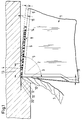
- the tool has at least one Insert 1, which in a known manner on a tool holder is attached.
- the insert 1 has a cutting wedge 2, which with a Rake face 3 and a free surface 4 is provided.
- the wedge angle 5 (Fig. 1) is in the range between about 70 ° and 95 ° and is preferably 90 °.
- the clearance angle on the cutting wedge 2 is in the range between 0 ° and about 3 °, preferably at 0 °.
- a workpiece 6 is machined with the indexable insert 1. Here, a chip 7 is lifted from the workpiece 6.
- the free area 4 is covered by at least one coating 8 Insert 1 formed.
- the coating 8 has a thickness 9 of more than at least about 0.02 mm. Instead of this one layer can also be provided several thin layers, which the Form layer 8.
- the rake face 3 has a coating 10 or has a larger one Mass fraction on as the coating 8 of the open area 4.
- the Coating 10 consists of shock-resistant material with a wear-reducing surface, with low roughness, insulating Properties and a low coefficient of friction. This will ensures that the rake face 3 has little wear subject to.
- the free space wear, the surface quality and dimensional accuracy of the workpiece 6 determined can be reduced, reducing the quality and / or quantity of the workpieces that can be produced with the cutting insert 1 6 can be increased. Due to a higher temperature resistance the cutting edge can change the speed of action between the tool and the workpiece 6 can be increased, whereby a Productivity gain is achieved.
- the rake angle 11 (FIG. 1) of the insert 1 is in the range of about -10 ° to about + 15 °.
- the free surface 4 has one on the cutting edge 12 adjoining area 13 which with the rake face 3 Includes clearance angle between about 0 ° and 3 °.
- the area 13 goes then into an open area 14, which has a larger clearance angle 15, which is in the range between about 5 ° and 10 °.
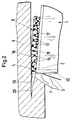
- a very thick wear-resistant layer 8 is applied to the open area 4 and is machined by simple circumferential dressing, similar to the dressing of a grinding wheel, whereby a highly precise tool is produced. After the application of the coating 8, before the first use of the insert 1 or the tool on the free surface 4, wear of the insert is deliberately anticipated.
- the coating 8 has a binder 16, in which wear-resistant elements 17 are embedded. They consist of individual CBN monocrystals or similar hard material particles such as Al 2 O 3 (corundum), silicon nitride, sapphire, natural or artificial diamond crystals and the like.
- the monocrystalline cutting elements 17 have a diameter or a cross-sectional width which is of the order of about 0.05 mm.
- the binder 16 enables the CBN monocrystals 17 to be adequately fastened over the service life of the insert 1. If 6 load impacts occur during the machining of the workpiece, the cutting elements 17 or their cutting edges can yield elastically.
- the CBN elements 17 are only provided on those active surfaces of the cutting wedge 2 which experience minor load impacts.
- the CBN elements 17 must show great wear resistance and high warm hardness. At the transition between the impact-loaded rake face 3 and the free face 4 there is a large number of such CBN elements 17, so that after wear of one element 17 the subsequent element is immediately available for further processing.
- the one formed from the CBN mono-elements 17 and the binder 16 Matrix has a sufficiently high layer thickness, which is advantageous is larger than 50 ⁇ m and enables a dressing process. With the sintering accuracy, the placement accuracy and the Panel seating accuracy in proportion to their corresponding cost shares be reduced. Nickel, for example, comes in as binder 16 Consideration.
- Each CBN element 17 has a cutting edge.
- the stochastic Failure probability of a cutting edge due to a formed by a plurality of CBN elements 17 to the cutting edge 12 adjoining area is increased so that longer service lives with the tool can be driven. If the insert 1 the free surface 4 in the manner described by dressing circumferentially are processed by the processing-specific mechanisms emerging forces in this anticipated Insert wear on the free surface 4 due to this special Surface design added.
- the cutting edge 12 will adequately supported by the layer matrix, the wear-resistant CBN elements 17 of the open area coating 8 a very form a small proportion of load.
- wear-resistant elements 17 Through the worked into the coating 8 of the open area 4 wear-resistant elements 17 is with the insert 1 the roughing chip 7 with a geometrically determined cutting edge and at the same time a chip removal similar to grinding with geome trically indefinite cutting performed. The geometrically un certain edges are cut from the edges of monocrystalline wear-resistant elements 17 are formed. The essential material removal can only from the geometrically determined cutting edge or their cutting edge 12 are performed.
- the wear-resistant elements 17 are preferably made of CBN, that is a highly wear-resistant, warm-hard cutting material. For this Elements also come in ceramic materials, diamond and the like into consideration.
- the wear-resistant embedded in the binder 16 Elements 17 cause abrasive surface contact between the cutting surface 4 and the workpiece surface 18. Thereby roughness peaks are smoothed. That way it can Workpiece 6 roughed and finished in a single operation become. There are no longer two processes for the rough and the Finishing necessary.
- the space requirement of the insert 1 is as small as possible held. It even becomes a cutting surface in the form of the surface segment 13 of a rotationally symmetrical body, that connects to the cutting edge 12.
- the free area 4 is with a designed very low load share. This is achieved that with sufficient stabilization of the cutting edge 12 the part of the indexable insert 1 pressing into the workpiece surface 18 is reduced to a minimum.
- the individual grains 17 form with their lying in the surface Edges the geometrically indefinite cutting edges, with those in limited Machining is possible. With these edges the workpiece surface 18 immediately following the removal of the chip 17 smoothed.
- the thickness 9 of the coating 8 of the open area 4 can be greater than 0.02 mm. This large layer thickness enables a larger one Elasticity of the wear-resistant elements forming the cutting edge 12 17. By coating with different grain sizes or Deposition times can be an exact absolute dimension of the cutting edge 12 can be achieved by the large number of individual wear-resistant Elements 17 is formed. Due to the low proportion of the Open space 4, 13 become vibrations between the workpiece 6 and steamed the tool.
- the tool equipped with the indexable inserts 1 enables a cutting process, where the cutting speed in the range between the turning, milling and grinding speeds in the range between approximately 100 m / min and 2000 m / min.
- the Cutting speed and the feed through the relative movement coordinated between the workpiece 6 and the tool Depending on the processing task for rough or fine machining, the Cutting speed and the feed through the relative movement coordinated between the workpiece 6 and the tool.
- a short can be between the cutting edge 12 and the free surface 4 be flat or curved cutting surface. 1 is the short flat cutting surface 13 is shown. Because of the described Anticipating wear by dressing the open area 4, a higher machining accuracy of the insert 1 is achieved.
- the free area 4 consists of a large number of geometrically indefinite cutting through the edges of wear-resistant Elements 17 are formed. But it is also possible that the open space 4 from a variety of geometrically determined cutting edges consists.
- the cutting wedge 2 or the insert 1 can be used as a wafer by sintering from different cutting materials or cutting material mixtures getting produced.
- the tool or the insert 1 consists of various Materials that match the stress during machining to be chosen. These materials can be in layers be applied, the different material layers different Can have thickness.
- the insert 1 has one Base body, which in the manner described on the rake face 3rd and at least one coating 10 on the free surface 4 or 8 has. On the rake face 3 and on the free face 4 can both in terms of type and number of different coatings be provided. These coatings 8, 10 can in turn consist of several individual layers.
- the coatings 8, 10 are advantageously evaporated onto the base body. For this are the PVD (physical vapor deposit), the CVD (chemical vapor deposition) and the Arc PVD process known. These procedures will since they are known, not explained in detail.
- the PVD process coatings with a thickness between about 2 and 5 ⁇ m, in the CVD process coatings in a thickness of about 12 to 15 ⁇ m and with the Arc PVD process coatings in one thickness up to about 50 ⁇ m can be produced. Depending on the desired thickness of the coatings 8 and 10, one of these methods is advantageous used.
- FIG 3 shows an embodiment in which a thin coating 21 is provided on the coating 8 with the wear-resistant elements 17. It consists of TiC, TiN, Al 2 O 3 , TiCN and the like and is applied by one of the methods described for the coating 8.
- the inserts 1 can be used in tools that for turning, milling, turning broaching or rotary milling.
- the individual cutting plates 1 lie on the circumference of this tool either on a cylinder jacket or any rotationally symmetrical Contour.
- the open areas 4 or their open area sections 13 form a polygon on the circumference of the tool.
- the open space section 13 can, in addition to the grinding described processed by laser or other dressing methods. Sharpening of this section 13 is also possible.
- all known methods of grinding technology are used, to deliberately remove layer components in the open area 4.
- the radius of the cutting edge 12 can be very can be kept small, so that when using the insert 1 a correspondingly low pushing load on the insert 1 is achieved.
- the dressing process can be extremely sharp Achieve cutting edge 12, creating the machined workpiece surface 18 has a high accuracy.
- the abrasive surface contact between the area 13 of the open space 4 of the insert 1 and the workpiece surface 18 In addition, the roughness tips are smoothed, which improves the machining accuracy is still increased.
- the machining accuracy can additionally can be increased by making the machine rigidity mechanical or is increased by control-related corrections. Also one Increases the cutting speed in the cutting process to increased machining accuracy.
- the Inserts 1 are today individual with an accuracy of ⁇ 5 microns or ground in a row.
- the plate seats of the tool will be with tuning elements to an accuracy of up to ⁇ 10 ⁇ m Voted.
- the simplest and cheapest solution is the insert 1 so that the clearance angle on the cutting part 2 between 0 and 3 °, preferably 0 °.
- This clearance angle will achieved by dressing the free area 4 in the area 13.
- Alone through this measure is compared to conventional turning or Inserts 1 significantly improved accuracy and economy achieved.
- those previously described other measures are meaningfully combined with each other, whereby the machining accuracy and economy even further be improved.
- the wear-resistant elements 17, which are preferably CBN monocrystals are only on those active surfaces of the Insert 1 provided that experience low load impacts, but a high level of wear resistance and a high level of hardness have to show.
- This effective area is the open area 4.
- the transition between the impact-loaded rake face 3 and that with the CBN crystals occupied area 13 is due to redundancy of the CBN grains determining the workpiece surface.
- This coating 8 is not designed as a fine-grained sintered cutting edge 12, but consists of single monocrystals that are sufficient Have the opportunity to move against each other.
- the binder 16 enables elastic integration of the CBN grains 17 and enables sufficient over the service life of the insert 1 Attachment of the CBN grains 17.
Landscapes
- Chemical & Material Sciences (AREA)
- Engineering & Computer Science (AREA)
- Mechanical Engineering (AREA)
- Chemical Kinetics & Catalysis (AREA)
- Materials Engineering (AREA)
- Metallurgy (AREA)
- Organic Chemistry (AREA)
- Inorganic Chemistry (AREA)
- Cutting Tools, Boring Holders, And Turrets (AREA)
Abstract
Description
Die Erfindung betrifft eine Schneidplatte, insbesondere eine Wendeplatte,
nach dem Oberbegriff des Anspruches 1, ein Verfahren zur
Herstellung einer solchen Schneidplatte nach dem Oberbegriff des
Anspruches 18, ein mit einer solchen Schneidplatte ausgestattetes
Werkzeug nach dem Oberbegriff des Anspruches 29 sowie ein Verfahren
zum Zerspanen eines Werkstückes unter Verwendung einer
solchen Schneidplatte oder eines solchen Werkzeuges nach dem
Oberbegriff des Anspruches 31.The invention relates to a cutting insert, in particular an indexable insert,
according to the preamble of claim 1, a method for
Production of such a cutting plate according to the preamble of
Die Bewegungen beim Zerspanvorgang sind Relativbewegungen zwischen einer Werkzeugschneide und dem Werkstück. Die Bewegungen werden durch eine Werkzeugmaschine erzeugt und können gerade, kreisförmig oder beliebig sein. Die Späne entstehen, wenn der aus Freifläche und Spanfläche gebildete Schneidkeil nach einer Zustellbewegung durch die Wirkbewegung in das Werkstück eindringt. The movements during the cutting process are relative movements between a cutting edge and the workpiece. The movements are generated by a machine tool and can be circular or any. The chips arise when the Cutting wedge formed from free face and rake face after a feed movement penetrates into the workpiece through the active movement.
Es sind Schneidkeile aus metallischen und nichtmetallischen Werkstoffen bekannt, zum Beispiel Schneidstahl, Hartmetall, Keramik, Mischkeramik, Korund, Siliciumcarbid, Borcarbid, Diamant und dergleichen.They are cutting wedges made of metallic and non-metallic materials known, for example cutting steel, hard metal, ceramic, Mixed ceramics, corundum, silicon carbide, boron carbide, diamond and the like.
Insbesondere Hartmetallschneidplatten können mit einer sehr dünnen Oberflächenschicht aus extrem feinkörnigen Carbiden oder Keramiken versehen werden und dadurch einen deutlichen Anstieg der Verschleißfestigkeit erfahren. Die wichtigsten Beschichtungsstoffe, die meist durch Aufdampfen im Vakuum aufgebracht werden, sind TiCN, TiN, Al2O3, und TiC. Zum Aufdampfen der Beschichtungsstoffe sind das PVD-, das CVD- und das Arc-PVD-Verfahren bekannt. Mit dem PVD-Verfahren können maximale Schichtdicken von etwa 2 bis 5 µm, mit dem CVD-Verfahren maximale Schichtdicken von etwa 12 bis 15 µm und beim Arc-PVD-Verfahren maximale Schichtdicken bis etwa 50 µm erreicht werden. Beim Eingriff des Werkzeuges in das Werkstück befindet sich der Schneidstoff oder seine Beschichtung in Flächenkontakt mit dem Werkstück entlang der Spanfläche. Die Schneidkante erfährt durch die spanabhebende Bewegung eine verschleißende Belastung, die zur einer Abflachung führt, dem sogenannten Span- und Freiflächenverschleiß. Die Beanspruchung der Flächen am Schneidkeil durch Druck- und Scherkräfte unter Temperatureinfluß ist jedoch unterschiedlich. Man unterscheidet dementsprechend unterschiedliche Versagensarten der verschiedenen Flächenelemente, zum Beispiel Freiflächenverschleiß, Kolkverschleiß, plastische Verformung, Kerbverschleiß, Kammrißbildung, Ermüdungsbruch, Ausbröckelung, Werkzeugbruch, Aufbauschneidenbildung. Diese Verschleißarten können parallel auftreten und beeinträchtigen den Zerspanprozeß und das Oberflächenergebnis am Werkstück. In der Praxis wird aus Wirtschaftlichkeitsgründen ein abrasiver Verschleiß zugelassen. Das Standzeitende der Schneidkante wird festgelegt als Parameter von Passivkraft, entstehender Wärme und Oberflächenqualität. Der Verschleiß durch Ausbruch von Schneidelementen wird generell als Standzeitende definiert.Tungsten carbide inserts in particular can be provided with a very thin surface layer made of extremely fine-grained carbides or ceramics and thus experience a significant increase in wear resistance. The most important coating materials, which are usually applied by vacuum deposition, are TiCN, TiN, Al 2 O 3 , and TiC. The PVD, CVD and arc PVD processes are known for evaporating the coating materials. With the PVD method, maximum layer thicknesses of approximately 2 to 5 μm can be achieved, with the CVD method, maximum layer thicknesses of approximately 12 to 15 μm and with the arc PVD method, maximum layer thicknesses up to approximately 50 μm can be achieved. When the tool engages the workpiece, the cutting material or its coating is in surface contact with the workpiece along the rake face. The cutting edge is subjected to a wear load due to the cutting movement, which leads to flattening, the so-called chip and flank wear. However, the stress on the surfaces of the cutting wedge by pressure and shear forces under the influence of temperature is different. Accordingly, a distinction is made between different types of failure of the various surface elements, for example open space wear, crater wear, plastic deformation, notch wear, comb crack formation, fatigue fracture, crumbling, tool breakage, built-up edge formation. These types of wear can occur in parallel and impair the cutting process and the surface result on the workpiece. In practice, abrasive wear is permitted for reasons of economy. The end of the service life of the cutting edge is determined as a parameter of passive force, the resulting heat and surface quality. The wear caused by cutting elements breaking out is generally defined as the end of the service life.
Die Schneidkeile werden aus Kostengründen nur als kleine Wendeschneidplatten ausgeführt, um den Werkzeuggrundkörper über viele Standzeiten nutzen zu können und um einen möglichst geringen Einsatz von teuren Schneidwerkstoffen zu erreichen. Gleichzeitig werden bei den heutigen Bearbeitungsprozessen die Anforderungen an die Genauigkeit der Schneidkanten immer größer (± 0,01 mm). Beim Sinterprozeß ist, bedingt durch die Schrumpfung, eine Wiederholgenauigkeit über mehrere Chargen nur mit zusätzlichen nachträglichen Schleifbearbeitungen erreichbar. Es müssen auch hohe Anforderungen an die Qualität der Aufnahmen für die Schneidplatten gestellt werden, die über viele Schneidplattenstandzeiten ein genaues Positionieren und Halten der wechselbaren Schneidplatten ermöglichen müssen. Das Einwechseln und Befestigen der Platten muß durch qualifiziertes Personal durchgeführt werden, da die Sauberkeit der Sitze und die Wiederholbarkeit der Befestigungsbewegung die Lagegenauigkeit der Schneidplatte beeinflußt.For cost reasons, the cutting wedges are only available as small indexable inserts executed to the tool body over many To be able to use downtimes and to minimize the use of expensive cutting materials. Be at the same time the requirements for today's machining processes the accuracy of the cutting edges is always greater (± 0.01 mm). At the Due to the shrinkage, the sintering process is a repeatability over several batches with only additional ones Grinding operations attainable. There must also be high demands to the quality of the recordings for the cutting inserts precise positioning over many insert lifetimes and hold the exchangeable inserts have to. The plates must be replaced and fastened qualified staff to be carried out because of the cleanliness of the Fits and the repeatability of the fastening movement the positional accuracy of the insert.
An der Schneidkante ist bei den herkömmlichen Schneidplatten ein Freiwinkel notwendig. Durch einen konstanten Vorschub wird die im Werkstück von der Schneidkante erzeugte Kontur laufend in den Bearbeitungskreis des Werkzeuges bewegt. Ein solcher Mechanismus macht Freiflächen für Gleich- und Gegenlauffräsen notwendig. Je geringer der Anteil der Schneidplattenbewegung am Schnittgeschwindigkeitsvektor ist, um so geringer ist dieser kinematische Bedarf an einem Freiflächenwinkel. Durch Erwärmung des Werkstückstoffes in der Zone hinter der Schneidkante kommt es durch Wärmeausdehnung zu einem Ausbauchen der bearbeiteten Werkstückoberfläche. Durch das Rückfedern von elastischen Verformungen des Werkstückstoffs durch die Passivkraft an der Schneidkante ist es vorteilhaft, einen Freiflächenwinkel zu haben. Die Größe des Freiwinkels wird durch das Verhältnis von Schnittgeschwindigkeit zu Vorschubgeschwindigkeit und der kinematischen Bewegung (Außen- oder Innenbearbeitung, rotierendes Werkzeug oder rotierendes Werkstück) beeinflußt. Bei gleichen Schnittparametern nimmt der benötigte Freiwinkel mit enger werdender Teilung der Schneidplatten zu. Dies ist vorteilhaft, um geringere Werkzeugwechselzeiten zu erreichen. Außerdem wird die Größe des Freiwinkels durch den Schneidenradius bestimmt. Für die Bearbeitung muß ein vernünftiges Verhältnis zwischen Schneidenradius und Spandicke gefunden werden. Da der mögliche effektive Vorschub in der Zeiteinheit beim Fräsen, Bohren und Räumen die Summe aus Vorschub/Zahn und Zähnezahl/Werkzeug ist, werden aus wirtschaftlichen Gründen enge Teilungen angestrebt.At the cutting edge there is a with the conventional inserts Clearance angle necessary. With a constant feed the Contour created by the cutting edge continuously in the machining circle of the tool moves. Such a mechanism makes free spaces necessary for parallel and counter-milling. The less the share of the insert movement in the cutting speed vector is, the lower is this kinematic requirement an open space angle. By heating the workpiece material in the zone behind the cutting edge occurs due to thermal expansion for bulging the machined workpiece surface. By springing back of elastic deformations of the workpiece material due to the passive force at the cutting edge, it is advantageous to have an open area angle. The size of the clearance angle is determined by the ratio of cutting speed to feed speed and the kinematic movement (external or internal machining, rotating tool or workpiece) influenced. With the same cutting parameters, the required clearance angle increases with narrowing pitch of the inserts. This is advantageous to achieve shorter tool change times. Furthermore is the size of the clearance angle by the cutting edge radius certainly. A reasonable relationship between Cutting edge radius and chip thickness can be found. Since the Possible effective feed in the unit of time when milling, drilling and broach the sum of feed / tooth and number of teeth / tool narrow division is sought for economic reasons.
Der Erfindung liegt die Aufgabe zugrunde, die gattungsgemäße Schneidplatte, das gattungsgemäße Verfahren, das gattungsgemäße Werkzeug sowie das gattungsgemäße Zerspanverfahren so auszubilden, daß in einfacher Weise und bei langen Standzeiten des Werkzeuges bzw. seiner Schneidplatte eine hohe Bearbeitungsgenauigkeit am Werkstück erzielt wird.The invention has for its object the generic Cutting insert, the generic method, the generic To design tools and the generic machining process in such a way that in a simple manner and with long tool downtimes or its insert a high machining accuracy is achieved on the workpiece.
Diese Aufgabe wird bei der gattungsgemäßen Schneidplatte erfindungsgemäß
mit den kennzeichnenden Merkmalen des Anspruches
1, beim gattungsgemäßen Verfahren erfindungsgemäß mit den
kennzeichnenden Merkmalen des Anspruches 18, beim gattungsgemäßen
Werkzeug erfindungsgemäß mit den kennzeichnenden Merkmalen
des Anspruches 29 und beim gattungsgemäßen Zerspanverfahren
erfindungsgemäß mit den kennzeichnenden Merkmalen des
Anspruches 31 gelöst. This object is achieved according to the invention in the generic insert
with the characterizing features of the claim
1, in the generic method according to the invention with the
characterizing features of
Bei der erfindungsgemäßen Schneidplatte liegt der Freiwinkel am Schneidkeil im Bereich zwischen 0° und etwa 3°. Durch diesen geringen Freiflächenwinkel, der sogar 0° sein kann, wird in einfacher Weise ein zufriedenstellendes Bearbeitungsergebnis erreicht. Beträgt der Freiflächenwinkel 0°, wird eine Schneidenfläche gebildet, die an die Schneidkante anschließt. Bei ausreichender Stabilisierung der Schneidkante wird der in die Werkstückoberfläche eindrückende Teil der Schneidplatte auf ein Minimum verringert.In the cutting insert according to the invention, the clearance angle lies on Cutting wedge in the range between 0 ° and approximately 3 °. Because of this low Flank angle, which can even be 0 °, is simple achieved a satisfactory machining result. Is the Flank angle 0 °, a cutting surface is formed, which is connected to the Cutting edge connects. With sufficient stabilization of the The cutting edge becomes the part that presses into the workpiece surface the insert is reduced to a minimum.
Mit dem erfindungsgemäßen Verfahren kann die Schneidplatte in kostengünstiger Weise einfach hergestellt werden. Auf die Schneidplatte wird die Spanfläche bzw. die Freifläche in Form einer Beschichtung aufgebracht, was in einfacher Weise möglich ist. Die in den jeweiligen Beschichtungen enthaltenen Schneidstoffe können entsprechend den bei der Bearbeitung mit der Schneidplatte auftretenden Belastungen ausgewählt werden.With the method according to the invention, the insert can be made more cost-effectively Easy way. On the The cutting surface is the rake face or the free face in the form of a Coating applied, which is possible in a simple manner. In the the cutting materials contained in the respective coatings corresponding to those that occur during machining with the insert Loads are selected.
Beim erfindungsgemäßen rotierenden Werkzeug liegen die Schneidkanten der Schneidplatten am Umfang des Werkzeuges auf einem gedachten Zylindermantel oder einer beliebigen rotationssymmetrischen Kontur.The cutting edges lie in the rotating tool according to the invention the inserts on the circumference of the tool on one imaginary cylinder jacket or any rotationally symmetrical Contour.
Beim Arbeiten mit dem erfindungsgemäßen Werkzeug bzw. der erfindungsgemäßen Schneidplatte wird mit der Freifläche unmittelbar im Anschluß an das Ablösen des Spanes vom Werkstück die freigelegte Bruchfläche am Werkstück geglättet. Auf diese Weise kann in einem einzigen Arbeitsgang geschruppt und geschlichtet werden. Durch den Glättungseffekt werden die beim Ablösen des Spanes auftretenden Rauhigkeitsspitzen in der Bruchfläche des Werkstückes beseitigt, so daß eine anschließende Nachbearbeitung des Werkstückes nicht erforderlich ist. When working with the tool according to the invention or the tool according to the invention The insert is placed directly in the open area Following the detachment of the chip from the workpiece, the exposed one Fractured surface smoothed on the workpiece. In this way, in one can be roughed and finished in a single operation. By the The smoothing effect occurs when the chip is removed Roughness peaks in the fractured surface of the workpiece eliminated, see above that subsequent finishing of the workpiece is not necessary is.
Weitere Merkmale der Erfindung ergeben sich aus den weiteren Ansprüchen, der Beschreibung und den Zeichnungen.Further features of the invention result from the further claims, the description and the drawings.
Die Erfindung wird anhand zweier in den Zeichnungen dargestellter Ausführungsbeispiele näher erläutert. Es zeigen
- Fig. 1
- einen Schneidkeil eines erfindungsgemäßen Werkzeuges, mit dem ein Span an einem Werkstück abgetragen wird,
- Fig. 2
- in vergrößerter Darstellung den Schneidkeilbereich des erfindungsgemaßen Werkzeuges,
- Fig. 3
- in einer Darstellung entsprechend Fig. 2 eine zweite Ausführungsform eines erfindungsgemäßen Werkzeuges.
- Fig. 1
- a cutting wedge of a tool according to the invention, with which a chip is removed from a workpiece,
- Fig. 2
- in an enlarged representation the cutting wedge area of the tool according to the invention,
- Fig. 3
- 2 shows a second embodiment of a tool according to the invention.
Das nicht im einzelnen dargestellte Werkzeug hat wenigstens eine
Wendeplatte 1, die in bekannter Weise auf einem Werkzeugträger
befestigt ist. Die Wendeplatte 1 hat einen Schneidkeil 2, der mit einer
Spanfläche 3 und einer Freifläche 4 versehen ist. Der Keilwinkel 5
(Fig. 1) liegt im Bereich zwischen etwa 70° und 95° und beträgt vorzugsweise
90°. Der Freiwinkel am Schneidkeil 2 liegt im Bereich zwischen
0° und etwa 3°, vorzugsweise bei 0°.The tool, not shown in detail, has at least one
Insert 1, which in a known manner on a tool holder
is attached. The insert 1 has a
Mit der Wendeplatte 1 wird ein Werkstück 6 spanend bearbeitet.
Hierbei wird vom Werkstück 6 ein Span 7 abgehoben.A
Da die Spanfläche 3 und die Freifläche 4 während der spanenden
Bearbeitung des Werkstückes 6 unterschiedlich beansprucht werden,
sind diesen beiden Flächen unterschiedliche Werkstoffe zugeordnet.
Die Freifläche 4 wird durch mindestens eine Beschichtung 8 der
Wendeplatte 1 gebildet. Die Beschichtung 8 hat eine Dicke 9 von
mehr als wenigstens etwa 0,02 mm. Anstelle dieser einen Schicht
können auch mehrere dünne Schichten vorgesehen sein, welche die
Schicht 8 bilden.Since the
Die Spanfläche 3 hat eine Beschichtung 10 bzw. weist einen größeren
Massenanteil auf als die Beschichtung 8 der Freifläche 4. Die
Beschichtung 10 besteht aus stoßunempfindlichen Werkstoff mit einer
verschleißmindernden Oberfläche, mit geringer Rauheit, isolierenden
Eigenschaften und einem niedrigen Reibwert. Dadurch wird
gewährleistet, daß die Spanfläche 3 nur einem geringem Verschleiß
unterliegt.The
Da die Freifläche 4 im Einsatz des Werkzeuges einen stärkeren Einfluß
auf die Werkstückqualität hat als die Spanfläche 3, besteht die
Freifläche 4 aus einem Schneidstoff oder einer Schneidstoffkomposition,
die eine höhere Abriebfestigkeit und eine größere Härte als der
Schneidstoff bzw. die Schneidstoffkombination der Beschichtung 10
der Spanfläche 3 hat. Somit können diese beiden Flächen 3 und 4
optimal an die Beanspruchung während der spanenden Bearbeitung
des Werkstückes 6 angepaßt werden. Die Werkstoffpaarungen am
Schneidkeil 2 werden verbessert, da den jeweiligen unterschiedlichen
Beanspruchungen an der Spanfläche 3 und an der Freifläche 4 jeweils
speziell zugeschnittene Schneidstoffe oder Schneidstoffmischungen
zugeordnet sind. Insbesondere der Freiflächenverschleiß,
der die Oberflächenqualität und die Maßhaltigkeit des Werkstückes
6 bestimmt, kann verringert werden, wodurch die Qualität
und/oder Quantität der mit der Schneidplatte 1 herstellbaren Werkstücke
6 erhöht werden können. Durch eine höhere Temperaturbeständigkeit
der Schneide kann die Wirkgeschwindigkeit zwischen
dem Werkzeug und dem Werkstück 6 gesteigert werden, wodurch ein
Produktivitätsgewinn erzielt wird. Since the
Der Spanwinkel 11 (Fig. 1) der Wendeplatte 1 liegt im Bereich von
etwa -10° bis etwa +15°. Die Freifläche 4 hat einen an die Schneidkante
12 anschließenden Bereich 13, der mit der Spanfläche 3 den
Freiwinkel zwischen etwa 0° und 3° einschließt. Der Bereich 13 geht
dann in einen Freiflächenbereich 14 über, der einen größeren Freiwinkel
15 hat, der im Bereich zwischen etwa 5° und 10° liegt.The rake angle 11 (FIG. 1) of the insert 1 is in the range of
about -10 ° to about + 15 °. The
Auf der Freifläche 4 wird eine sehr dicke verschleißfeste Schicht 8
aufgebracht, die durch einfaches Umfangsabrichten, ähnlich dem Abrichten
einer Schleifscheibe, bearbeitet wird, wodurch ein hochgenaues
Werkzeug erzeugt wird. Nach dem Aufbringen der Beschichtung
8 wird vor dem ersten Einsatz der Wendeplatte 1 bzw. des
Werkzeuges an der Freifläche 4 bewußt ein Schneidplattenverschleiß
vorweggenommen. Die Beschichtung 8 hat einen Binder 16, in den
verschleißfeste Elemente 17 eingebettet sind. Sie bestehen aus einzelnen
CBN-Monokristallen oder ähnlichen Hartstoffpartikeln, wie
Al2O3 (Korund), Siliziumnitrid, Saphir, natürliche oder künstliche Diamantkristalle
und dergleichen. Die monokristallinen Schneidelemente
17 haben einen Durchmesser bzw. eine Querschnittsbreite, die in der
Größenordnung von etwa 0,05 mm liegt. Der Binder 16 ermöglicht
über die Standzeit der Wendeplatte 1 eine ausreichende Befestigung
der CBN-Monokristalle 17. Treten während der Bearbeitung des
Werkstückes 6 Belastungsstöße auf, können die Schneidelemente 17
bzw. ihre Schneidkanten elastisch ausweichen. Die CBN-Elemente
17 sind nur an denjenigen Wirkflächen des Schneidkeiles 2 vorgesehen,
die geringe Belastungsstöße erfahren. Dabei müssen die CBN-Elemente
17 eine große Verschleißfestigkeit und hohe Warmhärte
zeigen. Am Übergang zwischen der stoßbelasteten Spanfläche 3 und
der Freifläche 4 befindet sich eine Vielzahl solcher CBN-Elemente
17, so daß nach einem Verschleiß des einen Elementes 17 sofort das
nachfolgende Element zur weiteren Bearbeitung bereitsteht. A very thick wear-
Die aus den CBN-Monoelementen 17 und dem Binder 16 gebildete
Matrix weist eine ausreichend hohe Schichtdicke auf, die vorteilhaft
größer als 50 µm ist und die einen Abrichtvorgang ermöglicht. Mit
ihm kann die Sintergenauigkeit, die Bestückungsgenauigkeit und die
Plattensitzgenauigkeit im Verhältnis ihrer entsprechenden Kostenanteile
reduziert werden. Als Binder 16 kommt beispielsweise Nickel in
Betracht.The one formed from the CBN mono-
Jedes CBN-Element 17 weist eine Schneidkante auf. Die stochastische
Ausfallwahrscheinlichkeit einer Schneidkante aufgrund einer
von mehreren CBN-Elementen 17 gebildeten, an die Schneidkante 12
anschließenden Fläche wird erhöht, so daß längere Standzeiten mit
dem Werkzeug gefahren werden können. Wird die Wendeplatte 1 an
der Freifläche 4 in der beschriebenen Weise durch Umfangsabrichten
bearbeitet, werden die durch die bearbeitungsspezifischen Mechanismen
entstehenden Abdrängkräfte bei diesem vorweggenommenen
Schneidplattenverschleiß an der Freifläche 4 durch diese spezielle
Oberflächengestaltung aufgenommen. Die Schneidkante 12 wird
durch die Schichtmatrix ausreichend gestützt, wobei die verschleißfesten
CBN-Elemente 17 der Freiflächenbeschichtung 8 einen sehr
geringen Traganteil bilden.Each
Mit dem Werkzeug bzw. seinen Wendeplatten 1 wird bereits beim
Abheben der Schruppspäne 7 eine sehr gute Werkstückoberfläche
erreicht. Dadurch läßt sich eine erhebliche Prozeßkettenverkürzung
erreichen. Durch die in die Beschichtung 8 der Freifläche 4 eingearbeiteten
verschleißfesten Elemente 17 wird mit der Wendeplatte 1
der Schruppspan 7 mit einer geometrisch bestimmten Schneide und
gleichzeitig eine Spanabhebung ähnlich dem Schleifen mit geome
trisch unbestimmten Schneiden durchgeführt. Die geometrisch unbe
stimmten Schneiden werden von den Kanten der monokristallinen
verschleißfesten Elemente 17 gebildet. Der wesentliche Werkstückstoffabtrag
kann nur von der geometrisch bestimmten Schneide bzw.
ihrer Schneidkante 12 durchgeführt werden.With the tool or its inserts 1 is already at
Lifting off the roughing chips 7 a very good workpiece surface
reached. This enables a considerable shortening of the process chain
to reach. Through the worked into the
Die verschleißfesten Elemente 17 bestehen vorzugsweise aus CBN,
das ein hochverschleißfester warmharter Schneidstoff ist. Für diese
Elemente kommen aber auch Keramikwerkstoffe, Diamant und dergleichen
in Betracht. Die in den Binder 16 eingebetteten verschleißfesten
Elemente 17 bewirken einen schleifenden Oberflächenkontakt
zwischen der Schneidfläche 4 und der Werkstückoberfläche 18. Dadurch
werden Rauheitsspitzen geglättet. Auf diese Weise kann das
Werkstück 6 in einem einzigen Vorgang geschruppt und geschlichtet
werden. Es sind nicht mehr zwei Vorgänge für die Grob- und die
Feinbearbeitung notwendig.The wear-
Der Freiflächenbedarf der Wendeplatte 1 wird so klein wie möglich
gehalten. Es wird sogar eine Schneidenfläche in Form des Flächensegmentes
13 eines rotationssymmetrischen Körpers zugelassen,
das an die Schneidkante 12 anschließt. Die Freifläche 4 wird mit einem
sehr geringen Traganteil gestaltet. Dies wird dadurch erreicht,
daß bei einer ausreichenden Stabilisierung der Schneidkante 12 der
in die Werkstückoberfläche 18 drückende Teil der Wendeplatte 1 auf
ein Minimum reduziert wird. Erreicht wird dies durch die einzelnen
monokristallinen Elemente 17, die in den Binder 16 eingebettet sind.
Die einzelnen Körner 17 bilden mit ihren in der Oberfläche liegenden
Kanten die geometrisch unbestimmten Schneiden, mit denen in begrenztem
Maße eine Zerspanung möglich ist. Mit diesen Kanten wird
die Werkstückoberfläche 18 unmittelbar im Anschluß an den Abtrag
des Spanes 17 geglättet. The space requirement of the insert 1 is as small as possible
held. It even becomes a cutting surface in the form of the
Trotz dieser einzelnen verschleißfesten Elemente 17 wird eine
scharfkantige Schneidkante 12 durch den beschriebenen Abrichtvorgang
nach der vollständigen Bestückung des Werkzeuges mit den
Wendeplatten 1 erreicht. Der entstehenden Gefahr von Schneidkantenausbrüchen
wird durch die Redundanz der die Schneidkante 12
bildenden verschleißfesten Elemente 17 begegnet. Innerhalb des Bereiches
13 (Fig. 1) der Freifläche 4 bilden die hintereinander liegenden
verschleißfesten Elemente 17 eine Schneidfläche. Da diese verschleißfesten
Elemente 17 auf dem gleichen Werkzeugradius liegen,
kann ein nachfolgendes Element 17 ein an der Schneidkante 12 ausgefallenes
Element 17 ersetzen. Da die verschleißfesten Elemente 17
im Binder 16 aufgenommen sind, haben die verschleißfesten Elemente
17 eine Stöße und Vibrationen abfedernde und dämpfende
Wirkung, wodurch die Neigung zum Ausbrechen verringert wird.Despite these individual wear-
Die Dicke 9 der Beschichtung 8 der Freifläche 4 kann größer als
0,02 mm sein. Diese große Schichtdicke ermöglicht eine größere
Elastizität der die Schneidkante 12 bildenden verschleißfesten Elemente
17. Durch Beschichtung mit unterschiedlichen Körnungen oder
Abscheidezeiten kann ein genaues Absolutmaß der Schneidkante 12
erreicht werden, die durch die Vielzahl der einzelnen verschleißfesten
Elemente 17 gebildet wird. Durch den geringen Traganteil der
Freifläche 4, 13 werden Schwingungen zwischen dem Werkstück 6
und dem Werkzeug gedämpft.The thickness 9 of the
Das mit den Wendeplatten 1 bestückte Werkzeug ermöglicht ein Zerspanverfahren,
bei dem die Schnittgeschwindigkeit im Bereich zwischen
den Dreh-, Fräs- und den Schleifgeschwindigkeiten liegt, also
im Bereich zwischen etwa 100 m/min und 2000 m/min. Je nach Bearbeitungsaufgabe
bei der Grob- oder Feinzerspanung werden die
Schnittgeschwindigkeit und der Vorschub durch die Relativbewegung
zwischen dem Werkstück 6 und dem Werkzeug aufeinander abgestimmt. The tool equipped with the indexable inserts 1 enables a cutting process,
where the cutting speed in the range between
the turning, milling and grinding speeds
in the range between approximately 100 m / min and 2000 m / min. Depending on the processing task
for rough or fine machining, the
Cutting speed and the feed through the relative movement
coordinated between the
Zwischen der Schneidkante 12 und der Freifläche 4 kann eine kurze
ebene oder gekrümmte Schneidfläche vorhanden sein. In Fig. 1 ist
die kurze ebene Schneidfläche 13 dargestellt. Aufgrund der beschriebenen
Verschleißvorwegnahme durch Abrichten der Freifläche
4 wird eine höhere Bearbeitungsgenauigkeit der Wendeplatte 1 erreicht.
Die Freifläche 4 besteht aus einer Vielzahl von geometrisch
unbestimmten Schneiden, die durch die Kanten der verschleißfesten
Elemente 17 gebildet werden. Es ist aber auch möglich, daß die Freifläche
4 aus einer Vielzahl von geometrisch bestimmten Schneiden
besteht.A short can be between the cutting
Der Schneidkeil 2 bzw. die Wendeplatte 1 kann als Wafer durch Sintern
aus unterschiedlichen Schneidstoffen oder Schneidstoffmischungen
hergestellt werden.The cutting
Das Werkzeug bzw. die Wendeplatte 1 besteht aus verschiedenen
Werkstoffen, die entsprechend der Beanspruchung während der Bearbeitung
ausgewählt werden. Diese Werkstoffe können in Schichten
aufgebracht sein, wobei die verschiedenen Werkstoffschichten unterschiedliche
Dicke haben können. Die Wendeplatte 1 hat einen
Grundkörper, der in der beschriebenen Weise an der Spanfläche 3
und an der Freifläche 4 jeweils mindestens eine Beschichtung 10
bzw. 8 aufweist. An der Spanfläche 3 und an der Freifläche 4 können
sowohl nach Art als auch nach Anzahl unterschiedliche Beschichtungen
vorgesehen sein. Diese Beschichtungen 8, 10 können ihrerseits
aus mehreren einzelnen Schichten bestehen. Die Beschichtungen 8,
10 werden vorteilhaft auf den Grundkörper aufgedampft. Hierfür sind
das PVD- (physical vapor deposit), das CVD- (chemical vapor deposition)
und das Arc-PVD-Verfahren bekannt. Diese Verfahren werden,
da sie bekannt sind, nicht näher erläutert. Mit dem PVD-Verfahren
können Beschichtungen in einer Dicke zwischen etwa 2 und 5 µm,
beim CVD-Verfahren Beschichtungen in einer Dicke von etwa 12 bis
15 µm und beim Arc-PVD-Verfahren Beschichtungen in einer Dicke
bis zu etwa 50 µm hergestellt werden. Je nach der gewünschten Dicke
der Beschichtungen 8 bzw. 10 wird eines dieser Verfahren vorteilhaft
eingesetzt.The tool or the insert 1 consists of various
Materials that match the stress during machining
to be chosen. These materials can be in layers
be applied, the different material layers different
Can have thickness. The insert 1 has one
Base body, which in the manner described on the rake face 3rd
and at least one
Es ist aber auch möglich, die unterschiedlichen Schichten der Beschichtungen
8 und 10 aus Schneidstoff oder Schneidstoffmischungen
durch Löten oder galvanotechnisch miteinander zu verbinden.
Diese unterschiedlichen Schichten aus Schneidstoff oder Schneidstoffmischungen
können durch Flammen, Laserspritzen oder durch
eine Plasmaabscheidung vorteilhaft miteinander verbunden werden.But it is also possible to use the different layers of the
Fig. 3 zeigt eine Ausführungsform, bei der auf der Beschichtung 8 mit
den verschleißfesten Elementen 17 eine dünne Beschichtung 21 vorgesehen
ist. Sie besteht aus TiC, TiN, Al2O3, TiCN und dergleichen
und wird nach einem der für die Beschichtung 8 beschriebenen Verfahren
aufgebracht.3 shows an embodiment in which a
Die Wendeplatten 1 können in Werkzeugen eingesetzt werden, die zum Drehen, Fräsen, Drehräumen oder Drehfräsen eingesetzt werden. Die einzelnen Schneidplatten 1 liegen am Umfang dieses Werkzeuges entweder auf einem Zylindermantel oder einer beliebigen rotationssymmetrischen Kontur.The inserts 1 can be used in tools that for turning, milling, turning broaching or rotary milling. The individual cutting plates 1 lie on the circumference of this tool either on a cylinder jacket or any rotationally symmetrical Contour.
Werden die Werkzeuge mit den Wendeplatten 1 als Drehwerkzeuge
eingesetzt, können die Freiflächen 4 bzw. ihre Freiflächenabschnitte
13 am Umfang des Werkzeuges ein Polygon bilden. Der Freiflächenabschnitt
13 kann außer durch das beschriebene Schleifen auch
mittels Laser oder sonstiger Abrichtverfahren bearbeitet werden.
Auch ein Schärfen dieses Abschnittes 13 ist möglich. Zur Herstellung
des Freiflächenbereiches 13 durch Abrichten oder Schärfen können
alle bekannten Verfahren der Schleiftechnologie eingesetzt werden,
um bewußt Schichtbestandteile in der Freifläche 4 zu entfernen. Besteht
die Beschichtung 8 an der Freifläche 4 in der beschriebenen
Weise aus den verschleißfesten Elemente 17, die in den elastischen
Binder 16 eingebettet sind, entsteht eine Vielzahl von geometrisch
unbestimmten Schneiden. Sie üben auch bei Schnittgeschwindigkeiten
entsprechend einer Fräsbearbeitung einen Glättungseffekt auf
der bearbeiteten Werkstückoberfläche 18 aus. Wie sich aus den Fig.
1 und 2 ergibt, wird durch die Wendeplatte 1 mit dem Schneidkeil 2
aus dem Werkstück 6 der Span 7 abgetrennt. Bei dieser Spanbildung
entsteht am Werkstück 6 ein voreilender Riß 19, der eine rauhe
Bruchfläche 20 bildet. Diese rauhe Bruchfläche 20 wird durch den
nachfolgenden Freiflächenabschnitt 13 mit seiner Vielzahl von geometrisch
unbestimmten Schneiden geglättet bzw. poliert bzw. geschliffen.
Darum ist nach dem Schruppvorgang eine Schlichtbearbeitung
des Werkstückes 6 nicht mehr notwendig. An der Schneidkante
12 entsteht ein gegen das Werkstück 6 gerichteter Druck, so daß das
Werkstück in diesem Bereich nach innen belastet wird. Da die verschleißfesten
Elemente 17 in den elastischen Binder 16 eingebettet
sind, kann der jeweils belastete Werkstückbereich hinter der
Schneidkante 12 bzw. hinter den jeweiligen verschleißfesten Elementen
17 zurückfedern. Die nachfolgenden verschleißfesten Elemente
17 können dann diesen zurückgefederten Werkstückbereich in
der beschriebenen Weise glätten und gegebenenfalls sogar abschleifen.
Ein mit den beschriebenen Wendeplatten 1 bestücktes
Werkzeug kann das Werkstück 6 in einem Arbeitsgang sehr genau
und mit geringen Kosten bearbeiten. Da an den Wendeplatten 1 in
der beschriebenen Weise durch den Abrichtvorgang eine Verschleißvorwegnahme
erzielt wird, kann in einfacher Weise die hohe Bearbeitungsgenauigkeit
erzielt werden. Bei der Verschleißvorwegnahme
durch das Abrichten der Freifläche im Bereich 13 wird die bekannte
Standzeitcharakteristik der Wendeplatte ausgenutzt. Nach 50 % des
radialen Verschleißes der Wendeplatte 1 hat sie erst 30 % ihrer
Standzeit erreicht. Durch die wesentlich geringeren Kosten der
Schneidplatte 1 kann der Verzicht auf bis zu 30 % der Standzeit
überkompensiert werden. Der Radius der Schneidkante 12 kann sehr
klein gehalten werden, wodurch im Einsatz der Wendeplatte 1 auch
eine entsprechend geringe Abdrängbelastung der Schneidplatte 1
erreicht wird. Durch den Abrichtvorgang läßt sich eine extrem scharfkantige
Schneidkante 12 erzielen, wodurch die bearbeitete Werkstückoberfläche
18 eine hohe Genauigkeit aufweist. Durch den
schleifenden Oberflächenkontakt zwischen dem Bereich 13 der Freifläche
4 der Wendeplatte 1 und der Werkstückoberfläche 18 werden
zudem die Rauheitsspitzen geglättet, wodurch die Bearbeitungsgenauigkeit
noch erhöht wird.Are the tools with the indexable inserts 1 as turning tools
used, the
Darüber hinaus kann die Bearbeitungsgenauigkeit zusätzlich noch dadurch erhöht werden, daß die Maschinensteifigkeit mechanisch oder durch steuerungstechnische Korrekturen erhöht wird. Auch eine Erhöhung der Schnittgeschwindigkeit beim Zerspanungsprozeß führt zu einer erhöhten Bearbeitungsgenauigkeit. Hierzu trägt auch die Vermeidung einer Getriebeentlastung durch mehrere im Eingriff befindliche Wendeplatten 1 bei. Darüber hinaus kann die Positionsgenauigkeit der Wendeplatten zur Werkzeugmitte erhöht werden. Die Wendeplatten 1 werden heute mit einer Genauigkeit von ± 5 µm einzeln oder in Reihe geschliffen. Die Plattensitze des Werkzeuges werden durch Abstimmelemente auf eine Genauigkeit von bis zu ± 10 µm abgestimmt. Durch eine sinnvolle Kombination dieser Maßnahmen, angepaßt auf den jeweiligen Einsatzfall (Drehen, Fräsen, Drehfräsen, Reiben, Räumen, Wirbeln und dergleichen), kann der spanabhebende Prozeß hinsichtlich Genauigkeit und Wirtschaftlichkeit im Vergleich zu den bekannten Werkzeugen wesentlich verbessert werden.In addition, the machining accuracy can additionally can be increased by making the machine rigidity mechanical or is increased by control-related corrections. Also one Increases the cutting speed in the cutting process to increased machining accuracy. The Avoidance of a transmission relief by several in mesh Inserts 1 at. In addition, the positional accuracy the inserts towards the center of the tool. The Inserts 1 are today individual with an accuracy of ± 5 microns or ground in a row. The plate seats of the tool will be with tuning elements to an accuracy of up to ± 10 µm Voted. By a sensible combination of these measures, adapted to the respective application (turning, milling, rotary milling, Rubbing, broaching, whirling and the like), the cutting Process in terms of accuracy and economy in comparison to be significantly improved to the known tools.
Die einfachste und kostengünstigste Lösung besteht darin, die Wendeplatte
1 so auszubilden, daß der Freiwinkel am Schneidteil 2 zwischen
0 und 3° liegt, vorzugsweise bei 0°. Dieser Freiwinkel wird
durch Abrichten der Freifläche 4 im Bereich 13 erzielt. Allein durch
diese Maßnahme wird im Vergleich zu herkömmlichen Wende- bzw.
Schneidplatten 1 eine wesentlich verbesserte Genauigkeit und Wirtschaftlichkeit
erzielt. Zusätzlich können die zuvor beschriebenen
weiteren Maßnahmen sinnvoll miteinander kombiniert werden, wodurch
die Bearbeitungsgenauigkeit und Wirtschaftlichkeit noch weiter
verbessert werden.The simplest and cheapest solution is the insert
1 so that the clearance angle on the cutting
Die verschleißfesten Elemente 17, die vorzugsweise CBN-Monokristalle
sind, sind lediglich an denjenigen Wirkflächen der
Wendeplatte 1 vorgesehen, die geringe Belastungsstöße erfahren,
dafür aber eine große Verschleißfestigkeit und eine hohe Warmhärte
zeigen müssen. Diese Wirkfläche ist die Freifläche 4. Der Übergang
zwischen der stoßbelasteten Spanfläche 3 und der mit den CBN-Kristallen
besetzten Fläche 13 ist durch eine Redundanz der die
Werkstückoberfläche bestimmenden CBN-Körner geprägt. Diese Beschichtung
8 ist nicht als feinkörnig gesinterte Schneidkante 12 ausgeführt,
sondern besteht aus einzelnen Monokristallen, die eine ausreichende
Bewegungsmoglichkeit gegeneinander haben. Der Binder
16 ermöglicht eine elastische Einbindung der CBN-Körner 17 und
ermöglicht über die Standzeit der Wendeplatte 1 eine ausreichende
Befestigung der CBN-Körner 17. Bei Belastungsstößen können die
Schneidkanten der jeweiligen CBN-Körner 17 in der beschriebenen
Weise ausweichen. Nach dem Abrichtvorgang bildet die elastische
Matrix durch Verschleiß den geringen Traganteil des Bereiches 13
der Freifläche 4.The wear-
Claims (34)
dadurch gekennzeichnet, daß am Schneidkeil (2) ein Freiwinkel zwischen 0° und etwa 3° vorgesehen ist.Cutting insert, in particular an insert, for a cutting tool, with a cutting wedge, which is formed by a rake face and a free face
characterized in that a clearance angle between 0 ° and approximately 3 ° is provided on the cutting wedge (2).
dadurch gekennzeichnet, daß der Freiwinkel am Schneidkeil (2) 0° beträgt.Cutting insert according to claim 1,
characterized in that the clearance angle on the cutting wedge (2) is 0 °.
dadurch gekennzeichnet, daß die Spanfläche (3) und die Freifläche (4) aus unterschiedlichen Werkstoffen bestehen und vorteilhaft einander in einer Schneidkante (12) schneiden.Cutting insert according to claim 1 or 2,
characterized in that the rake face (3) and the free face (4) consist of different materials and advantageously cut one another in one cutting edge (12).
dadurch gekennzeichnet, daß die Schneidkante (12) durch eine Vielzahl von geometrisch bestimmten Schneidelementen (17) gebildet ist, die neben- und hintereinander vorgesehen sind. Cutting insert according to claim 3,
characterized in that the cutting edge (12) is formed by a plurality of geometrically determined cutting elements (17) which are provided next to and behind one another.
dadurch gekennzeichnet, daß die Schneidkante (12) durch eine Vielzahl von geometrisch unbestimmten Schneidelementen (17) gebildet ist, die neben- und hintereinander vorgesehen sind.Cutting insert according to claim 3,
characterized in that the cutting edge (12) is formed by a plurality of geometrically indefinite cutting elements (17) which are provided next to and behind one another.
dadurch gekennzeichnet, daß die Schneidelemente (17) in der Span- und/oder in der Freifläche (3, 4) vorgesehen sind.Cutting insert according to claim 4 or 5,
characterized in that the cutting elements (17) are provided in the chip and / or in the free surface (3, 4).
dadurch gekennzeichnet, daß die Freifläche (4) und vorzugsweise auch die Spanfläche (3) durch die Oberseite einer Beschichtung (8 bzw. 10) eines Grundkörpers der Schneidplatte (1) gebildet sind.Cutting insert according to one of claims 1 to 6,
characterized in that the free surface (4) and preferably also the rake surface (3) are formed by the top of a coating (8 or 10) of a base body of the insert (1).
dadurch gekennzeichnet, daß die Beschichtung (8) der Freifläche (4) dicker ist als die Beschichtung (10) der Spanfläche (3), vorzugsweise hat die Beschichtung (8) eine Dicke von mehr als etwa 0,02 mm.Cutting insert according to claim 7,
characterized in that the coating (8) of the free surface (4) is thicker than the coating (10) of the rake surface (3), preferably the coating (8) has a thickness of more than about 0.02 mm.
dadurch gekennzeichnet, daß die Beschichtungen (8, 10) unterschiedliche Körnungen aufweisen.Cutting insert according to claim 7 or 8,
characterized in that the coatings (8, 10) have different grain sizes.
dadurch gekennzeichnet, daß die Freifläche (4) einen an die Schneidkante (12) anschließenden ebenen oder gekrümmten Abschnitt (13) aufweist. Cutting insert according to one of claims 1 to 9,
characterized in that the free surface (4) has a flat or curved section (13) adjoining the cutting edge (12).
dadurch gekennzeichnet, daß die Beschichtungen (8, 10) der Freifläche (4) und der Spanfläche (3) nach Art und Anzahl unterschiedliche Schichten aufweisen.Cutting insert according to one of claims 7 to 10,
characterized in that the coatings (8, 10) of the free surface (4) and the rake surface (3) have different layers in terms of type and number.
dadurch gekennzeichnet, daß die Beschichtung (8) der Freifläche (4) einen größeren Massenanteil aufweist als die Beschichtung (10) der Spanfläche (3).Cutting insert according to one of claims 7 to 11,
characterized in that the coating (8) of the free surface (4) has a greater mass fraction than the coating (10) of the rake surface (3).
dadurch gekennzeichnet, daß die Spanfläche (3) aus stoßunempfindlichem Werkstoff besteht, und daß vorteilhaft die Freifläche (4) aus einem Schneidstoff oder einer Schneidstoffkomposition mit höherer Abriebfestigkeit und/oder größerer Härte als die Spanfläche (3) besteht.Cutting insert according to one of claims 1 to 12,
characterized in that the rake face (3) consists of shock-resistant material and that the free face (4) advantageously consists of a cutting material or a cutting material composition with higher abrasion resistance and / or greater hardness than the rake face (3).
dadurch gekennzeichnet, daß die Freifläche (4) eine Vielzahl von geometrisch bestimmten und/oder unbestimmten Schneidelementen (17) aufweist, die vorzugsweise CBN-Monokristalle sind, und daß vorzugsweise die Schneidelemente (17) aus Al2O3 (Korund), Siliziumnitrid, Saphir, natürlichen oder künstlichen Diamantkristallen oder CBN-Monokristallen bestehen.Cutting insert according to one of claims 1 to 13,
characterized in that the free surface (4) has a plurality of geometrically determined and / or undefined cutting elements (17), which are preferably CBN monocrystals, and in that the cutting elements (17) made of Al 2 O 3 (corundum), silicon nitride, Sapphire, natural or artificial diamond crystals or CBN monocrystals.
dadurch gekennzeichnet, daß auf die Beschichtung (8) der Freifläche (4) eine weitere Beschichtung (21) aufgetragen ist, die vorteilhaft dünner ist als die Beschichtung (8) der Freifläche (4). Cutting insert according to one of claims 1 to 14,
characterized in that a further coating (21) is applied to the coating (8) of the free surface (4), which is advantageously thinner than the coating (8) of the free surface (4).
dadurch gekennzeichnet, daß die weitere Beschichtung (21) aus TiC, TiN, Al2O3, TiCN und dergleichen besteht.Cutting insert according to claim 15,
characterized in that the further coating (21) consists of TiC, TiN, Al 2 O 3 , TiCN and the like.
dadurch gekennzeichnet, daß der Spanwinkel (11) im Bereich von etwa -10° bis etwa +15° und vorzugsweise der Keilwinkel (5) des Schneidkeils (2) zwischen etwa 70° und etwa 95° liegen.Cutting insert according to one of claims 1 to 16,
characterized in that the rake angle (11) is in the range from about -10 ° to about + 15 ° and preferably the wedge angle (5) of the cutting wedge (2) is between about 70 ° and about 95 °.
dadurch gekennzeichnet, daß auf die Schneidplatte (1) zur Bildung der Spanfläche (3) und der Freifläche (4) jeweils mindestens eine Beschichtung (10; 8, 21) so aufgebracht wird, daß der Freiwinkel der Freifläche (4) zwischen 0° und etwa 3° liegt.Method for producing a cutting insert, in particular an insert, according to one of claims 1 to 17, in which at least one rake face and at least one free face are provided on the cutting insert,
characterized in that at least one coating (10; 8, 21) is applied to the cutting plate (1) to form the rake face (3) and the free face (4) such that the clearance angle of the free face (4) is between 0 ° and is about 3 °.
dadurch gekennzeichnet, daß für den Freiwinkel 0° gewählt wird.Method according to claim 18,
characterized in that 0 ° is selected for the clearance angle.
dadurch gekennzeichnet, daß die jeweilige Beschichtung (8, 21; 10) auf einen Grundkörper der Schneidplatte (1), vorzugsweise mit einem PVD-, CVD- oder einem Arc-PVD-Verfahren, aufgedampft wird.Method according to claim 18 or 19,
characterized in that the respective coating (8, 21; 10) is evaporated onto a base body of the cutting insert (1), preferably using a PVD, CVD or an arc PVD method.
dadurch gekennzeichnet, daß zur Herstellung der jeweiligen Beschichtung (8, 21; 10) mehrere Schichten aufgebracht werden. Method according to one of claims 18 to 20,
characterized in that several layers are applied to produce the respective coating (8, 21; 10).
dadurch gekennzeichnet, daß die Schichten durch Löten oder galvanotechnisch oder durch Sintern miteinander verbunden werden.22. The method of claim 21,
characterized in that the layers are connected to one another by soldering or by electroplating or by sintering.
dadurch gekennzeichnet, daß die Schichten durch Flamm- oder Laserspritzen miteinander verbunden werden.22. The method of claim 21,
characterized in that the layers are connected to one another by flame or laser spraying.
dadurch gekennzeichnet, daß die Schichten durch Plasmaabscheidung miteinander verbunden werden.22. The method of claim 21,
characterized in that the layers are connected to one another by plasma deposition.
dadurch gekennzeichnet, daß die Beschichtungen (8, 21; 10) mit unterschiedlichen Körnungen und/oder mit unterschiedlichen Abscheidezeiten hergestellt werden.Method according to one of claims 18 to 24,
characterized in that the coatings (8, 21; 10) are produced with different grain sizes and / or with different deposition times.
dadurch gekennzeichnet, daß als Beschichtung (8) für die Freifläche (4) monokristalline CBN-Körner (17) oder ähnliche Hartstoffpartikel, wie Al2O3 (Korund), Siliziumnitrid, natürliche oder künstliche Diamantkristalle und dergleichen, verwendet werden, die durch ein Bindemittel (16), wie Nickel, zusammengehalten werden, und daß vorteilhaft ein Teil (13) der Beschichtung (8) abgerichtet wird, wobei Schichtbestandteile entfernt werden.Method according to one of claims 18 to 25,
characterized in that monocrystalline CBN grains (17) or similar hard material particles such as Al 2 O 3 (corundum), silicon nitride, natural or artificial diamond crystals and the like are used as a coating (8) for the open area (4), which are characterized by a Binders (16), such as nickel, are held together and that part (13) of the coating (8) is advantageously dressed, layer components being removed.
dadurch gekennzeichnet, daß auf die Beschichtung (8) der Freifläche (4) eine weitere Beschichtung (21) aufgebracht wird, für die vorzugsweise TiC, TiN, Al2O3, TiCN und dergleichen verwendet wird. Method according to one of claims 18 to 26,
characterized in that a further coating (21) is applied to the coating (8) of the free surface (4), for which TiC, TiN, Al 2 O 3 , TiCN and the like are preferably used.
dadurch gekennzeichnet, daß der Schneidkeil (2) als Wafer durch Sintern aus unterschiedlichen Schneidstoffen oder Schneidstoffmischungen hergestellt wird.Method according to one of claims 18 to 27,
characterized in that the cutting wedge (2) is produced as a wafer by sintering from different cutting materials or cutting material mixtures.
dadurch gekennzeichnet, daß die Schneidkanten (12) der Schneidplatten (1) am Umfang des Werkzeuges auf einem gedachten Zylindermantel oder einer beliebigen rotationssymmetrischen Kontur liegen.Tool provided with cutting inserts according to one of Claims 1 to 17,
characterized in that the cutting edges (12) of the cutting plates (1) lie on the circumference of the tool on an imaginary cylinder jacket or any rotationally symmetrical contour.
dadurch gekennzeichnet, daß bei Einsatz als Drehwerkzeug die Freiflächen (4) am Umfang des Werkzeuges ein Polygon bilden.Tool according to claim 29,
characterized in that when used as a turning tool the free surfaces (4) form a polygon on the circumference of the tool.
dadurch gekennzeichnet, daß mit der Freifläche (4) die durch den abgehobenen Span (7) freigelegte Bruchfläche (20) des Werkstückes (6) geglättet wird.Method for machining a workpiece using a cutting plate according to one of claims 1 to 17 or using a tool according to claim 29 or 30, in which chips are lifted off the workpiece with the cutting plate,
characterized in that the fractured surface (20) of the workpiece (6) exposed by the removed chip (7) is smoothed with the free surface (4).
dadurch gekennzeichnet, daß die Bruchfläche (20) mit dem abgerichteten Teil der Freifläche (4) oder durch eine Vielzahl von geometrisch unbestimmten Schneiden der Schneidelemente (17) geglättet wird. A method according to claim 31,
characterized in that the fracture surface (20) is smoothed with the dressed part of the free surface (4) or by a large number of geometrically undefined cutting edges of the cutting elements (17).
dadurch gekennzeichnet, daß die Glättung bei einer Schnittgeschwindigkeit entsprechend einer Fräsbearbeitung vorgenommen wird, und daß vorteilhaft die Schnittgeschwindigkeit beim Zerspanen des Werkstückes (6) im Bereich zwischen Dreh-, Fräs- und Schleifgeschwindigkeiten liegt.A method according to claim 31 or 32,
characterized in that the smoothing is carried out at a cutting speed corresponding to a milling operation, and that the cutting speed during the machining of the workpiece (6) is advantageously in the range between turning, milling and grinding speeds.
dadurch gekennzeichnet, daß je nach Bearbeitungsaufgabe bei der Grob- oder Feinzerspanung Schnittgeschwindigkeit und Vorschub, gebildet durch eine Relativbewegung zwischen Werkstück (6) und Werkzeug, aufeinander abgestimmt werden.Method according to one of claims 31 to 33,
characterized in that the cutting speed and feed, formed by a relative movement between workpiece (6) and tool, are coordinated with one another depending on the machining task in the case of rough or fine machining.
Applications Claiming Priority (2)
| Application Number | Priority Date | Filing Date | Title |
|---|---|---|---|
| DE19742765A DE19742765A1 (en) | 1997-09-27 | 1997-09-27 | Cutting plate, in particular indexable insert, method for producing such a cutting plate, tool equipped with such cutting plates and method for machining a workpiece using such a cutting plate or using such a tool |
| DE19742765 | 1997-09-27 |
Publications (2)
| Publication Number | Publication Date |
|---|---|
| EP0908259A2 true EP0908259A2 (en) | 1999-04-14 |
| EP0908259A3 EP0908259A3 (en) | 2003-01-22 |
Family
ID=7843865
Family Applications (1)
| Application Number | Title | Priority Date | Filing Date |
|---|---|---|---|
| EP98115382A Withdrawn EP0908259A3 (en) | 1997-09-27 | 1998-08-17 | Cutting insert, method of manufacturing the same, tool and machining method using this insert |
Country Status (3)
| Country | Link |
|---|---|
| US (1) | US6508150B1 (en) |
| EP (1) | EP0908259A3 (en) |
| DE (1) | DE19742765A1 (en) |
Cited By (3)
| Publication number | Priority date | Publication date | Assignee | Title |
|---|---|---|---|---|
| US6682274B2 (en) | 2000-10-02 | 2004-01-27 | Walter Ag | Cutting insert with wear detection |
| EP1473102A2 (en) * | 2003-04-29 | 2004-11-03 | Fette GmbH | Cutting tool |
| DE10332101A1 (en) * | 2003-07-15 | 2005-02-03 | Kennametal Inc. | Cutting tool and method for reducing the wear mark width in a cutting tool |
Families Citing this family (15)
| Publication number | Priority date | Publication date | Assignee | Title |
|---|---|---|---|---|
| US6952987B2 (en) * | 1999-12-17 | 2005-10-11 | Boehringer Werkzeugmaschinen Gmbh | Method for scroll-free machining rotationally symmetrical surfaces |
| US7175376B2 (en) | 2001-04-27 | 2007-02-13 | Thk Co., Ltd. | Method of cutting long-sized hardened steel material and cutting device |
| SE529855C2 (en) * | 2005-12-30 | 2007-12-11 | Sandvik Intellectual Property | Coated cemented carbide inserts and ways of making this |
| ATE507796T1 (en) | 2007-06-07 | 2011-05-15 | Nobel Biocare Services Ag | METHOD FOR PRODUCING A DENTAL PRODUCT |
| ES2702779T3 (en) * | 2007-06-07 | 2019-03-05 | Nobel Biocare Services Ag | Procedure and sintered product to form a dental bridge |
| US7922267B2 (en) * | 2007-08-10 | 2011-04-12 | Krueger International, Inc. | Movable monitor and keyboard storage system for a worksurface |
| EP2072020A1 (en) * | 2007-12-17 | 2009-06-24 | Nobel Biocare Services AG | A method of producing a dental ceramic product |
| US9656335B2 (en) | 2013-03-08 | 2017-05-23 | United Technologies Corporation | Broach tool rake face with a tailored surface topography |
| US9296054B2 (en) * | 2013-05-23 | 2016-03-29 | Kennametal Inc. | Indexable cutting insert with a triangular shape |
| KR101537718B1 (en) * | 2014-04-23 | 2015-07-20 | 한국야금 주식회사 | Cutting tools having coated layer removed partly |
| US11376675B2 (en) * | 2014-04-23 | 2022-07-05 | Korloy Inc. | Cutting tool having partially-removed film formed thereon |
| DE102015222491B4 (en) | 2015-11-13 | 2023-03-23 | Kennametal Inc. | Cutting tool and method of making same |
| DE102016105847A1 (en) * | 2016-03-31 | 2017-10-05 | Kohnle GmbH | Cutting body and cutting tool |
| JP6977034B2 (en) * | 2017-06-21 | 2021-12-08 | 京セラ株式会社 | Manufacturing method for covering tools, cutting tools and cutting products |
| CN107570772B (en) * | 2017-09-07 | 2020-04-28 | 株洲钻石切削刀具股份有限公司 | Cutting insert having a plurality of different coatings on a surface thereof |
Citations (4)
| Publication number | Priority date | Publication date | Assignee | Title |
|---|---|---|---|---|
| US2164303A (en) * | 1937-12-08 | 1939-07-04 | Alfred J Berg | Tool for cutting or turning |
| US3369283A (en) * | 1964-02-06 | 1968-02-20 | Diadur Aktiebolag | Cutting insert for chip cutting machining and means for manufacturing such cutting inserts |
| JPS6076902A (en) * | 1983-10-03 | 1985-05-01 | Yamaha Motor Co Ltd | Highly hard material cutting tool |
| US5266388A (en) * | 1990-09-17 | 1993-11-30 | Kennametal Inc. | Binder enriched coated cutting tool |
Family Cites Families (11)
| Publication number | Priority date | Publication date | Assignee | Title |
|---|---|---|---|---|
| DE305189C (en) * | ||||
| FR62025E (en) * | 1951-09-25 | 1955-06-02 | Insertion tool for machine tools | |
| US2846193A (en) * | 1957-01-07 | 1958-08-05 | Chadderdon Jack | Milling cutter for use in oil wells |
| GB1463137A (en) * | 1974-04-24 | 1977-02-02 | Coal Ind | Rock cutting tip inserts application |
| US4194860A (en) * | 1978-06-26 | 1980-03-25 | The Valeron Corporation | Face milling cutter |
| US4561810A (en) * | 1981-12-16 | 1985-12-31 | General Electric Company | Bi-level cutting insert |
| US5178645A (en) * | 1990-10-08 | 1993-01-12 | Sumitomo Electric Industries, Ltd. | Cutting tool of polycrystalline diamond and method of manufacturing the same |
| SE9301811D0 (en) * | 1993-05-27 | 1993-05-27 | Sandvik Ab | CUTTING INSERT |
| DE4319505C2 (en) * | 1993-06-12 | 1996-02-15 | Walter Ag | Indexable insert |
| US5722803A (en) * | 1995-07-14 | 1998-03-03 | Kennametal Inc. | Cutting tool and method of making the cutting tool |
| US5750247A (en) * | 1996-03-15 | 1998-05-12 | Kennametal, Inc. | Coated cutting tool having an outer layer of TiC |
-
1997
- 1997-09-27 DE DE19742765A patent/DE19742765A1/en not_active Withdrawn
-
1998
- 1998-08-17 EP EP98115382A patent/EP0908259A3/en not_active Withdrawn
- 1998-09-25 US US09/161,011 patent/US6508150B1/en not_active Expired - Fee Related
Patent Citations (4)
| Publication number | Priority date | Publication date | Assignee | Title |
|---|---|---|---|---|
| US2164303A (en) * | 1937-12-08 | 1939-07-04 | Alfred J Berg | Tool for cutting or turning |
| US3369283A (en) * | 1964-02-06 | 1968-02-20 | Diadur Aktiebolag | Cutting insert for chip cutting machining and means for manufacturing such cutting inserts |
| JPS6076902A (en) * | 1983-10-03 | 1985-05-01 | Yamaha Motor Co Ltd | Highly hard material cutting tool |
| US5266388A (en) * | 1990-09-17 | 1993-11-30 | Kennametal Inc. | Binder enriched coated cutting tool |
Cited By (7)
| Publication number | Priority date | Publication date | Assignee | Title |
|---|---|---|---|---|
| US6682274B2 (en) | 2000-10-02 | 2004-01-27 | Walter Ag | Cutting insert with wear detection |
| DE10048899B4 (en) * | 2000-10-02 | 2004-04-08 | Walter Ag | Cutting insert with wear detection |
| EP1473102A2 (en) * | 2003-04-29 | 2004-11-03 | Fette GmbH | Cutting tool |
| EP1473102A3 (en) * | 2003-04-29 | 2006-08-02 | Fette GmbH | Cutting tool |
| DE10332101A1 (en) * | 2003-07-15 | 2005-02-03 | Kennametal Inc. | Cutting tool and method for reducing the wear mark width in a cutting tool |
| US7431747B2 (en) | 2003-07-15 | 2008-10-07 | Kennametal Inc. | Cutting tool and method of reducing the width of wear mark on a cutting tool |
| DE10332101B4 (en) * | 2003-07-15 | 2016-02-04 | Kennametal Inc. | Cutting tool and method for its production |
Also Published As
| Publication number | Publication date |
|---|---|
| US6508150B1 (en) | 2003-01-21 |
| DE19742765A1 (en) | 1999-04-01 |
| EP0908259A3 (en) | 2003-01-22 |
Similar Documents
| Publication | Publication Date | Title |
|---|---|---|
| EP0908259A2 (en) | Cutting insert, method of manufacturing the same, tool and machining method using this insert | |
| EP3528989B1 (en) | Hob peeling tool and method for hard-fine machining of pre-toothed workpieces | |
| EP1317985B1 (en) | Reamer | |
| DE60108536T2 (en) | Ball end mill | |
| DE69928154T2 (en) | Ultra-fine groove cutting tip and ultra-fine grooving tool | |
| DE69630832T2 (en) | Process for the production of diamond coated cutting inserts | |
| EP0830228B1 (en) | Metal-cutting process for machining cylindrical contours, device for carrying out the process and cutting insert therefor | |
| EP3385014B1 (en) | Drilling tool and method for manufacturing a drilling tool for the machining of workpieces | |
| EP2036675B1 (en) | Dressing gear and dressing tool for dressing of a toothed tool which is used for finish machining of workpieces, in particular gears | |
| DE69509600T2 (en) | Rotating cutting tool and its manufacturing method | |
| DE102019003976B4 (en) | drill | |
| EP0038929B1 (en) | Dressing tool | |
| EP2859975A1 (en) | Rotary cutting tool with helical extending cutting edges and method for producing same | |
| DE4338077C2 (en) | Honing element | |
| DE69503537T2 (en) | CVD diamond cutting tools | |
| EP1768807A1 (en) | Cutting insert provided with structured surfaces | |
| EP3892407A1 (en) | Tool for the machining of non-metallic materials | |
| EP0912283B1 (en) | High-speed milling | |
| WO2007031337A1 (en) | Method and device for machining workpieces | |
| EP1944110B1 (en) | Method of processing and machining tools for the machining of workpieces by chip removal | |
| DE4226335C2 (en) | Use of a honing process for honing inner cylinder surfaces, tools therefor and cylinders | |
| DE102016105847A1 (en) | Cutting body and cutting tool | |
| DE19757242A1 (en) | Drilling tool for drilling in solid material | |
| WO2021001150A1 (en) | Machining tool having asymmetrical teeth bearing cutting particles | |
| DE202008016389U1 (en) | Dressing wheel and dressing tool for dressing of teeth having tools for the finishing of a workpiece, in particular a gear |
Legal Events
| Date | Code | Title | Description |
|---|---|---|---|
| PUAI | Public reference made under article 153(3) epc to a published international application that has entered the european phase |
Free format text: ORIGINAL CODE: 0009012 |
|
| AK | Designated contracting states |
Kind code of ref document: A2 Designated state(s): AT BE CH CY DE DK ES FI FR GB GR IE IT LI LU MC NL PT SE |
|
| AX | Request for extension of the european patent |
Free format text: AL;LT;LV;MK;RO;SI |
|
| PUAL | Search report despatched |
Free format text: ORIGINAL CODE: 0009013 |
|
| AK | Designated contracting states |
Kind code of ref document: A3 Designated state(s): AT BE CH CY DE DK ES FI FR GB GR IE IT LI LU MC NL PT SE |
|
| AX | Request for extension of the european patent |
Free format text: AL;LT;LV;MK;RO;SI |
|
| RIC1 | Information provided on ipc code assigned before grant |
Free format text: 7B 23B 27/14 A, 7C 23C 30/00 B |
|
| AKX | Designation fees paid |
Designated state(s): AT DE ES FR GB IT SE |
|
| STAA | Information on the status of an ep patent application or granted ep patent |
Free format text: STATUS: THE APPLICATION IS DEEMED TO BE WITHDRAWN |
|
| 18D | Application deemed to be withdrawn |
Effective date: 20030723 |