EP0908021B1 - A method and network of controlling initial power ramp-up in cdma systems by using short codes - Google Patents
A method and network of controlling initial power ramp-up in cdma systems by using short codes Download PDFInfo
- Publication number
- EP0908021B1 EP0908021B1 EP97930175A EP97930175A EP0908021B1 EP 0908021 B1 EP0908021 B1 EP 0908021B1 EP 97930175 A EP97930175 A EP 97930175A EP 97930175 A EP97930175 A EP 97930175A EP 0908021 B1 EP0908021 B1 EP 0908021B1
- Authority
- EP
- European Patent Office
- Prior art keywords
- base station
- code
- subscriber unit
- short code
- access code
- Prior art date
- Legal status (The legal status is an assumption and is not a legal conclusion. Google has not performed a legal analysis and makes no representation as to the accuracy of the status listed.)
- Expired - Lifetime
Links
Images


Classifications
-
- H—ELECTRICITY
- H04—ELECTRIC COMMUNICATION TECHNIQUE
- H04W—WIRELESS COMMUNICATION NETWORKS
- H04W52/00—Power management, e.g. Transmission Power Control [TPC] or power classes
- H04W52/04—Transmission power control [TPC]
- H04W52/54—Signalisation aspects of the TPC commands, e.g. frame structure
- H04W52/60—Signalisation aspects of the TPC commands, e.g. frame structure using different transmission rates for TPC commands
-
- H—ELECTRICITY
- H04—ELECTRIC COMMUNICATION TECHNIQUE
- H04B—TRANSMISSION
- H04B1/00—Details of transmission systems, not covered by a single one of groups H04B3/00 - H04B13/00; Details of transmission systems not characterised by the medium used for transmission
- H04B1/69—Spread spectrum techniques
- H04B1/707—Spread spectrum techniques using direct sequence modulation
- H04B1/7073—Synchronisation aspects
- H04B1/7075—Synchronisation aspects with code phase acquisition
- H04B1/70751—Synchronisation aspects with code phase acquisition using partial detection
- H04B1/70753—Partial phase search
-
- H—ELECTRICITY
- H04—ELECTRIC COMMUNICATION TECHNIQUE
- H04B—TRANSMISSION
- H04B1/00—Details of transmission systems, not covered by a single one of groups H04B3/00 - H04B13/00; Details of transmission systems not characterised by the medium used for transmission
- H04B1/69—Spread spectrum techniques
- H04B1/707—Spread spectrum techniques using direct sequence modulation
- H04B1/7073—Synchronisation aspects
- H04B1/7075—Synchronisation aspects with code phase acquisition
- H04B1/70755—Setting of lock conditions, e.g. threshold
-
- H—ELECTRICITY
- H04—ELECTRIC COMMUNICATION TECHNIQUE
- H04B—TRANSMISSION
- H04B1/00—Details of transmission systems, not covered by a single one of groups H04B3/00 - H04B13/00; Details of transmission systems not characterised by the medium used for transmission
- H04B1/69—Spread spectrum techniques
- H04B1/707—Spread spectrum techniques using direct sequence modulation
- H04B1/7073—Synchronisation aspects
- H04B1/7075—Synchronisation aspects with code phase acquisition
- H04B1/70758—Multimode search, i.e. using multiple search strategies
-
- H—ELECTRICITY
- H04—ELECTRIC COMMUNICATION TECHNIQUE
- H04B—TRANSMISSION
- H04B1/00—Details of transmission systems, not covered by a single one of groups H04B3/00 - H04B13/00; Details of transmission systems not characterised by the medium used for transmission
- H04B1/69—Spread spectrum techniques
- H04B1/707—Spread spectrum techniques using direct sequence modulation
- H04B1/7073—Synchronisation aspects
- H04B1/7075—Synchronisation aspects with code phase acquisition
- H04B1/708—Parallel implementation
-
- H—ELECTRICITY
- H04—ELECTRIC COMMUNICATION TECHNIQUE
- H04L—TRANSMISSION OF DIGITAL INFORMATION, e.g. TELEGRAPHIC COMMUNICATION
- H04L1/00—Arrangements for detecting or preventing errors in the information received
- H04L1/12—Arrangements for detecting or preventing errors in the information received by using return channel
- H04L1/16—Arrangements for detecting or preventing errors in the information received by using return channel in which the return channel carries supervisory signals, e.g. repetition request signals
- H04L1/18—Automatic repetition systems, e.g. Van Duuren systems
- H04L1/1812—Hybrid protocols; Hybrid automatic repeat request [HARQ]
-
- H—ELECTRICITY
- H04—ELECTRIC COMMUNICATION TECHNIQUE
- H04W—WIRELESS COMMUNICATION NETWORKS
- H04W52/00—Power management, e.g. Transmission Power Control [TPC] or power classes
- H04W52/04—Transmission power control [TPC]
- H04W52/30—Transmission power control [TPC] using constraints in the total amount of available transmission power
- H04W52/36—Transmission power control [TPC] using constraints in the total amount of available transmission power with a discrete range or set of values, e.g. step size, ramping or offsets
- H04W52/367—Power values between minimum and maximum limits, e.g. dynamic range
-
- H—ELECTRICITY
- H04—ELECTRIC COMMUNICATION TECHNIQUE
- H04W—WIRELESS COMMUNICATION NETWORKS
- H04W52/00—Power management, e.g. Transmission Power Control [TPC] or power classes
- H04W52/04—Transmission power control [TPC]
- H04W52/38—TPC being performed in particular situations
- H04W52/50—TPC being performed in particular situations at the moment of starting communication in a multiple access environment
-
- H—ELECTRICITY
- H04—ELECTRIC COMMUNICATION TECHNIQUE
- H04W—WIRELESS COMMUNICATION NETWORKS
- H04W88/00—Devices specially adapted for wireless communication networks, e.g. terminals, base stations or access point devices
- H04W88/02—Terminal devices
-
- H—ELECTRICITY
- H04—ELECTRIC COMMUNICATION TECHNIQUE
- H04B—TRANSMISSION
- H04B1/00—Details of transmission systems, not covered by a single one of groups H04B3/00 - H04B13/00; Details of transmission systems not characterised by the medium used for transmission
- H04B1/69—Spread spectrum techniques
- H04B1/707—Spread spectrum techniques using direct sequence modulation
- H04B1/7073—Synchronisation aspects
- H04B1/7075—Synchronisation aspects with code phase acquisition
- H04B1/7077—Multi-step acquisition, e.g. multi-dwell, coarse-fine or validation
-
- H—ELECTRICITY
- H04—ELECTRIC COMMUNICATION TECHNIQUE
- H04B—TRANSMISSION
- H04B2201/00—Indexing scheme relating to details of transmission systems not covered by a single group of H04B3/00 - H04B13/00
- H04B2201/69—Orthogonal indexing scheme relating to spread spectrum techniques in general
- H04B2201/707—Orthogonal indexing scheme relating to spread spectrum techniques in general relating to direct sequence modulation
- H04B2201/70701—Orthogonal indexing scheme relating to spread spectrum techniques in general relating to direct sequence modulation featuring pilot assisted reception
-
- H—ELECTRICITY
- H04—ELECTRIC COMMUNICATION TECHNIQUE
- H04B—TRANSMISSION
- H04B2201/00—Indexing scheme relating to details of transmission systems not covered by a single group of H04B3/00 - H04B13/00
- H04B2201/69—Orthogonal indexing scheme relating to spread spectrum techniques in general
- H04B2201/707—Orthogonal indexing scheme relating to spread spectrum techniques in general relating to direct sequence modulation
- H04B2201/70702—Intercell-related aspects
-
- H—ELECTRICITY
- H04—ELECTRIC COMMUNICATION TECHNIQUE
- H04B—TRANSMISSION
- H04B2201/00—Indexing scheme relating to details of transmission systems not covered by a single group of H04B3/00 - H04B13/00
- H04B2201/69—Orthogonal indexing scheme relating to spread spectrum techniques in general
- H04B2201/707—Orthogonal indexing scheme relating to spread spectrum techniques in general relating to direct sequence modulation
- H04B2201/70703—Orthogonal indexing scheme relating to spread spectrum techniques in general relating to direct sequence modulation using multiple or variable rates
-
- H—ELECTRICITY
- H04—ELECTRIC COMMUNICATION TECHNIQUE
- H04B—TRANSMISSION
- H04B2201/00—Indexing scheme relating to details of transmission systems not covered by a single group of H04B3/00 - H04B13/00
- H04B2201/69—Orthogonal indexing scheme relating to spread spectrum techniques in general
- H04B2201/707—Orthogonal indexing scheme relating to spread spectrum techniques in general relating to direct sequence modulation
- H04B2201/70707—Efficiency-related aspects
- H04B2201/7071—Efficiency-related aspects with dynamic control of receiver resources
-
- H—ELECTRICITY
- H04—ELECTRIC COMMUNICATION TECHNIQUE
- H04W—WIRELESS COMMUNICATION NETWORKS
- H04W52/00—Power management, e.g. Transmission Power Control [TPC] or power classes
- H04W52/04—Transmission power control [TPC]
- H04W52/30—Transmission power control [TPC] using constraints in the total amount of available transmission power
- H04W52/36—Transmission power control [TPC] using constraints in the total amount of available transmission power with a discrete range or set of values, e.g. step size, ramping or offsets
- H04W52/362—Aspects of the step size
Definitions
- the present invention relates generally to CDMA communication systems. More specifically, the present invention relates to initial power ramp-up in a CDMA communication system.
- Wireless communication systems are being utilized in a variety of applications where land line based systems are impractical or impossible to use.
- Applications of wireless communications include cellular phone communications, communications in remote locations, and temporary communications for disaster recovery.
- Wireless communication systems have also become an economically viable alternative to replacing aging telephone lines and outdated telephone equipment.
- the portion of the RF spectrum available for use by wireless communication systems is a critical resource.
- the RF spectrum must be shared among all commercial, governmental and military applications. There is a constant desire to improve the efficiency of wireless communication systems in order to increase system capacity.
- CDMA wireless communication systems have shown particular promise in this area. Although more traditional time division multiple access (TDMA) and frequency division multiple access (FDMA) systems have improved using the latest technological advances, CDMA systems, in particular Broadband Code Division Multiple AccessTM (B-CDMATM) systems, have significant advantages over TDMA and FDMA systems. This efficiency is due to the improved coding and modulation density, interference rejection and multipath tolerance of B-CDMATM systems, as well as reuse of the same spectrum in every communication cell.
- B-CDMATM Broadband Code Division Multiple AccessTM
- the format of CDMA communication signals also makes it extremely difficult to intercept calls, thereby ensuring greater privacy for callers and providing greater immunity against fraud.
- a CDMA system In a CDMA system, the same portion of the frequency spectrum is used for communication by all subscriber units.
- Each subscriber unit's baseband data signal is multiplied by a code sequence, called the “spreading code”, which has a much higher rate than the data.
- the ratio of the spreading code rate to the data symbol rate is called the “spreading factor” or the “processing gain”.
- This coding results in a much wider transmission spectrum than the spectrum of the baseband data signal, hence the technique is called “spread spectrum”.
- Subscriber units and their communications can be discriminated by assigning a unique spreading code to each communication link which is called a CDMA channel. Since all communications are sent over the same frequency band, each CDMA communication overlaps communications from other subscriber units and noise-related signals in both frequency and time.
- the control of transmission power is particularly critical when a subscriber unit is attempting to initiate communications with a base station and a power control loop has not yet been established.
- the transmission power required from a subscriber unit changes continuously as a function of the propagation loss, interference from other subscribers, channel noise, fading and other channel characteristics. Therefore, a subscriber unit does not know the power level at which it should start transmitting. If the subscriber unit begins transmitting at a power level that is too high, it may interfere with the communications of other subscriber units and may even terminate the communications of other subscriber units. If the initial transmission power level is too low, the subscriber unit will not be detected by the base station and a communication link will not be established.
- U.S. Patent No. 5,056,109 discloses a transmission power control system wherein the transmission power of the subscriber unit is based upon periodic signal measurements from both the subscriber unit and the base station.
- the base station transmits a pilot signal to all subscriber units which analyze the received pilot signal, estimate the power loss in the transmitted signal and adjust their transmission power accordingly.
- Each subscriber unit includes a non-linear loss output filter which prevents sudden increases in power which would cause interference to other subscriber units. This method is too complex to permit a base station to quickly acquire a subscriber unit while limiting the interference to other subscriber units.
- EP 0 565 507 A2 discloses a system for minimizing interference between two radio stations at the initiation of radio communications.
- a mobile station initiates a low level access signal and incrementally increases the transmission power level until the base station detects the signal. Once detected, the power level of the message is maintained at the detected level so that the signal interference is avoided.
- EP 0 565 507 A2 also discloses a method for synchronizing random access communications between mobile stations and the base station despite the variations in the distance between them.
- the invention provides a method for controlling transmission power according to claim 1 and a network including a system for initial power control according to claim 15. Further aspects of the invention according to the dependent claims are provided.
- the present invention comprises a novel method of controlling transmission power during the establishment of a channel in a CDMA communication system by utilizing the transmission of a short code from a subscriber unit to a base station during initial power ramp-up.
- the short code is a sequence for detection by the base station which has a much shorter period than a conventional spreading code.
- the ramp-up starts from a power level that is guaranteed to be lower than the required power level for detection by the base station.
- the subscriber unit quickly increases transmission power while repeatedly transmitting the short code until the signal is detected by the base station. Once the base station detects the short code, it sends an indication to the subscriber unit to cease increasing transmission power.
- the use of short codes limits power overshoot and interference to other subscriber stations and permits the base station to quickly synchronize to the spreading code used by the subscriber unit.
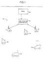
- the communication network 10 generally comprises one or more base stations 14 , each of which is in wireless communication with a plurality of subscriber units 16 , which may be fixed or mobile. Each subscriber unit 16 communicates with either the closest base station 14 or the base station 14 which provides the strongest communication signal.
- the base stations 14 also communicate with a base station controller 20, which coordinates communications among base stations 14 .
- the communication network 10 may also be connected to a public switched telephone network (PSTN) 22 , wherein the base station controller 20 also coordinates communications between the base stations 14 and the PSTN 22.
- PSTN public switched telephone network
- each base station 14 communicates with the base station controller 20 over a wireless link, although a land line may also be provided. A land line is particularly applicable when a base station 14 is in close proximity to the base station controller 20 .
- the base station controller 20 performs several functions. Primarily, the base station controller 20 provides all of the operations, administrative and maintenance (OA&M) signaling associated with establishing and maintaining all of the wireless communications between the subscriber units 16 , the base stations 14 , and the base station controller 20 .
- the base station controller 20 also provides an interface between the wireless communication system 10 and the PSTN 22 . This interface includes multiplexing and demultiplexing of the communication signals that enter and leave the system 10 via the base station controller 20 .
- the wireless communication system 10 is shown employing antennas to transmit RF signals, one skilled in the art should recognize that communications may be accomplished via microwave or satellite uplinks. Additionally, the functions of the base station controller 20 may be combined with a base station 14 to form a "master base station".
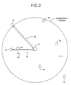
- a two-way communication channel (link) 18 comprises a signal transmitted 20 (Tx) from the base station 14 to the subscriber unit 16 and a signal received 22 (Rx) by the base station 14 from the subscriber unit 16 .
- the Tx signal 20 is transmitted from the base station 14 and is received by the subscriber unit 16 after a propagation delay ⁇ t.
- the Rx 22 signal originates at the subscriber unit 16 and terminates at the base station 14 after a further propagation delay ⁇ t. Accordingly, the round trip propagation delay is 2 ⁇ t.
- the base station 14 has an operating range of approximately 30 kilometers.
- the round trip propagation delay 24 associated with a subscriber unit 16 at the maximum operating range is 200 microseconds.
- the present invention is directed to initial power ramp-up and synchronization during the establishment of a communication channel.
- the base station 14 continuously transmits a pilot code 40 to all of the subscriber units 16 located within the transmitting range of the base station 14 .
- the pilot code 40 is a spreading code which carries no data bits.
- the pilot code 40 is used for subscriber unit 16 acquisition and synchronization, as well as for determining the parameters of the adaptive matched filter used in the receiver.
- the subscriber unit 16 must acquire the pilot code 40 transmitted by the base station 14 before it can receive or transmit any data. Acquisition is the process whereby the subscriber unit 16 aligns its locally generated spreading code with the received pilot code 40 . The subscriber unit 16 searches through all of the possible phases of the received pilot code 40 until it detects the correct phase, (the beginning of the pilot code 40 ).
- the subscriber unit 16 then synchronizes its transmit spreading code to the received pilot code 40 by aligning the beginning of its transmit spreading code to the beginning of the pilot code 40 .
- One implication of this receive and transmit synchronization is that the subscriber unit 16 introduces no additional delay as far as the phase of the spreading codes are concerned. Accordingly, as shown in Figure 3 , the relative delay between the pilot code 40 transmitted from the base station 14 and the subscriber unit's transmit spreading code 42 received at the base station 14 is 2 ⁇ t, which is solely due to the round trip propagation delay.
- the pilot code is 29,877,120 chips in length and takes approximately 2 to 5 seconds to transmit, depending on the spreading factor.
- the length of the pilot code 40 was chosen to be a multiple of the data symbol no matter what kind of data rate or bandwidth is used. As is well known by those of skill in the art, a longer pilot code 40 has better randomness properties and the frequency response of the pilot code 40 is more uniform. Additionally, a longer pilot code 40 provides low channel cross correlation, thus increasing the capacity of the system 10 to support more subscriber units 16 with less interference. The use of a long pilot code 40 also supports a greater number of random short codes. For synchronization purposes, the pilot code 40 is chosen to have the same period as all of the other spreading codes used by the system 10 . Thus, once a subscriber unit 16 acquires the pilot code 40, it is synchronized to all other signals transmitted from the base station 14.
- the subscriber unit 16 During idle periods, when a call is not in progress or pending, the subscriber unit 16 remains synchronized to the base station 14 by periodically reacquiring the pilot code 40 . This is necessary for the subscriber unit 16 to receive and demodulate any downlink transmissions, in particular paging messages which indicate incoming calls.
- the base station 14 When a communication link is desired, the base station 14 must acquire the signal transmitted from the subscriber unit 16 before it can demodulate the data. The subscriber unit 16 must transmit an uplink signal for acquisition by the base station 14 to begin establishing the two-way communication link.
- a critical parameter in this procedure is the transmission power level of the subscriber unit 16 . A transmission power level that is too high can impair communications in the whole service area, whereas a transmission power level that is too low can prevent the base station 14 from detecting the uplink signal.
- the subscriber unit 16 starts transmitting at a power level guaranteed to be lower than what is required and increases transmission power output until the correct power level is achieved. This avoids sudden introduction of a strong interference, hence improving system 10 capacity.
- the base station 14 begins by continuously transmitting a periodic pilot code 40 to all subscriber units 16 located within the operating range of the base station 14 (step 100) .
- the base station 14 searches (step 101) for an "access code" 42 transmitted by a subscriber unit 16 .
- the access code 42 is a known spreading code transmitted from a subscriber unit 16 to the base station 14 during initiation of communications and power ramp-up.
- the base station 14 must search through all possible phases (time shifts) of the access code 42 transmitted from the subscriber unit 16 in order to find the correct phase. This is called the "acquisition” or the "detection” process (step 101) .
- the longer the access code 42 the longer it takes for the base station 14 to search through the phases and acquire the correct phase.
- the relative delay between signals transmitted from the base station 14 and return signals received at the base station 14 corresponds to the round trip propagation delay 2 ⁇ t.
- the maximum delay occurs at the maximum operating range of the base station 14 , known as the cell boundary. Accordingly, the base station 14 must search up to as many code phases as there are in the maximum round trip propagation delay, which is typically less code phases than there are in a code period.
- the ratio L Rc/Rb is called the spreading factor or the processing gain.
- the cell boundary radius is 30 km, which corresponds to approximately between 1000 and 2500 code phases in the maximum round trip delay, depending on the processing gain.
- step 102 If the base station 14 has not detected the access code after searching through the code phases corresponding to the maximum round trip delay the search is repeated starting from the phase of the pilot code 40 which corresponds to zero delay (step 102) .
- the pilot code 40 from the base station 14 is received at the subscriber unit 16 which periodically synchronizes its transmit spreading code generator thereto (step 103) . If synchronization with the pilot code 40 is lost, the subscriber unit 16 reacquires the pilot code 40 and resynchronizes (step 104) .
- the subscriber unit 16 When it is desired to initiate a communication link, the subscriber unit 16 starts transmitting the access code 42 back to the base station 14 (step 106) .
- the subscriber unit 16 continuously increases the transmission power while retransmitting the access code 42 (step 108) until it receives an acknowledgment from the base station 14 .
- the base station 14 detects the access code 42 at the correct phase once the minimum power level for reception has been achieved (step 110) .
- the base station 14 subsequently transmits an access code detection acknowledgment signal (step 112) to the subscriber unit 16.
- the subscriber unit Upon receiving the acknowledgment, the subscriber unit ceases the transmission power increase (step 114) .
- closed loop power control and call setup signaling is performed (step 116) to establish the two-way communication link.
- this embodiment limits subscriber unit 16 transmission power, acquisition of the subscriber unit 16 by the base station 14 in this manner may lead to unnecessary power overshoot from the subscriber unit 16 , thereby reducing the performance of the system 10 .
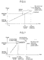
- the transmission power output profile of the subscriber unit 16 is shown in Figure 5.
- the subscriber unit 16 starts transmitting at the starting transmission power level P 0 , which is a power level guaranteed to be less than the power level required for detection by the base station 14.
- the subscriber unit 16 continually increases the transmission power level until it receives the detection indication from the base station 14 .
- the access code 42 must: 1) be received at a sufficient power level; and 2) be detected at the proper phase. Accordingly, referring to Figure 5, although the access code 42 is at a sufficient power level for detection by the base station 14 at t p , the base station 14 must continue searching for the correct phase of the access code 42 which occurs at t A .
- the subscriber unit 16 Since the subscriber unit 16 continues to increase the output transmission power level until it receives the detection indication from the base station 14 , the transmission power of the access code 42 exceeds the power level required for detection by the base station 14 . This causes unnecessary interference to all other subscriber units 16 . If the power overshoot is too large, the interference to other subscriber units 16 may be so severe as to terminate ongoing communications of other subscriber units 16 .
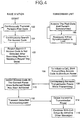
- the preferred embodiment of the present invention utilizes "short codes" and a two-stage communication link establishment procedure to achieve fast power ramp-up without large power overshoots.
- the spreading code transmitted by the subscriber unit 16 is much shorter than the rest of the spreading codes (hence the term short code), so that the number of phases is limited and the base station 14 can quickly search through the code.
- the short code used for this purpose carries no data.
- the base station 14 periodically and continuously transmits the pilot code to all subscriber units 16 located within the operating range of the base station 14 (step 150) .
- the base station 14 also continuously searches for a short code transmitted by the subscriber unit 16 (step 152) .
- the subscriber unit 16 acquires the pilot code and synchronizes its transmit spreading code generator to the pilot code.
- the subscriber unit 16 also periodically checks to ensure it is synchronized. If synchronization is lost, the subscriber unit 16 reacquires the pilot signal transmitted by the base station (step 156) .
- the subscriber unit 16 starts transmitting a short code at the minimum power level P 0 (step 158) and continuously increases the transmission power level while retransmitting the short code (step 160) until it receives an acknowledgment from the base station 14 that the short code has been detected by the base station 14 .
- the access code in the preferred embodiment is approximately 30 million chips in length. However, the short code is much smaller.
- the short code can be chosen to be any length that is sufficiently short to permit quick detection. There is an advantage in choosing a short code length such that it divides the access code period evenly.
- the short code is preferably chosen to be 32, 64 or 128 chips in length. Alternatively, the short code may be as short as one symbol length, as will be described in detail hereinafter.
- the base station 14 Since the start of the short code and the start of the access code are synchronized, once the base station 14 acquires the short code, the base station 14 knows that the corresponding phase of the access code is an integer multiple of N chips from the phase of the short code where N is the length of the short code. Accordingly, the base station 14 does not have to search all possible phases corresponding to the maximum round trip propagation delay.
- the short code Using the short code, the correct phase for detection by the base station 14 occurs much more frequently.
- the short code is quickly detected (step 162) and the transmission power overshoot is limited.
- the transmission power ramp-up rate may be significantly increased without concern for a large power overshoot.
- the power ramp-up rate using the short code is 1 dB per millisecond.
- the base station 14 subsequently transmits a short code detection indication signal (step 164) to the subscriber unit 16 which enters the second stage of the power ramp-up upon receiving this indication.
- the subscriber unit 16 ceases transmitting the short code (step 166) and starts continuously transmitting a periodic access code (step 166) .
- the subscriber unit 16 continues to ramp-up its transmission power while transmitting the access code, however the ramp-up rate is now much lower than the previous ramp-up rate used with the short code (step 168) .
- the ramp-up rate with the access code is preferably 0.05 dB per millisecond. The slow ramp-up avoids losing synchronization with the base station 14 due to small changes in channel propagation characteristics.
- the base station 14 has detected the short code at the proper phase and power level (step 162) .
- the base station 14 must now synchronize to the access code which is the same length as all other spreading codes and much longer than the short code. Utilizing the short code, the base station 14 is able to detect the proper phase of the access code much more quickly.
- the base station 14 quickly acquires the access code of the proper phase and power level by: 1) detecting the short code; and 2) determining the proper phase of the access code by searching every N chips of the access code from the beginning of the short code.
- the base station 14 restarts the search for the access code by searching every chip instead of every N chips (step 172) .
- the base station 14 transmits an access code detection acknowledgment (step 176) to the subscriber unit 16 which ceases the transmission power increase (step 178) upon receiving this acknowledgment.
- closed loop power control and call setup signaling is performed (step 180) to establish the two-way communication link.
- the subscriber unit 16 may ramp-up the transmission power level at a much higher rate by using a short code.
- the short code is quickly detected after the transmission power level surpasses the minimum detection level, thus minimizing the amount of transmission power overshoot.
- the short codes are dynamically selected and updated in accordance with the following procedure.
- the period of the short code is equal to one symbol length and the start of each period is aligned with a symbol boundary.
- the short codes are generated from a regular length spreading code. A symbol length portion from the beginning of the spreading code is stored and used as the short code for the next 3 milliseconds. Every 3 milliseconds, a new symbol length portion of the spreading code replaces the old short code. Since the spreading code period is an integer multiple of 3 milliseconds, the same short codes are repeated once every period of the spreading code. Periodic updating of the short code averages the interference created by the short code over the entire spectrum.
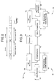
- the base station 14 comprises a receiver section 50 , a transmitter section 52 and a diplexer 54 .
- An RF receiver 56 receives and down-converts the RF signal received from the diplexer 54 .
- the receive spreading code generator 58 outputs a spreading code to both the data receiver 60 and the code detector 62 .
- the spreading code is correlated with the baseband signal to extract the data signal which is forwarded for further processing.
- the received baseband signal is also forwarded to the code detector 62 which detects the access code or the short code from the subscriber unit 16 and adjusts the timing of the spreading code generator 58 to establish a communication channel 18 .
- the transmit spreading code generator 64 outputs a spreading code to the data transmitter 66 and the pilot code transmitter 68 .
- the pilot code transmitter 68 continuously transmits the periodic pilot code.
- the data transmitter 66 transmits the short code detect indication and access code detect acknowledgment after the code detector 62 has detected the short code or the access code respectively.
- the data transmitter also sends other message and data signals.
- the signals from the data transmitter 66 and the pilot code transmitter 68 are combined and up-converted by the RF transmitter 70 for transmission to the subscriber units 16 .
- the subscriber unit 16 comprises a receiver section 72, a transmitter section 74 and a diplexer 84 .
- An RF receiver 76 receives and down-converts the RF signal received from the diplexer 84 .
- a pilot code detector 80 correlates the spreading code with the baseband signal to acquire the pilot code transmitted by the base station 16 . In this manner, the pilot code detector 80 maintains synchronization with the pilot code.
- the receiver spreading code generator 82 generates and outputs a spreading code to the data receiver 78 and the pilot code detector 80 .
- the data receiver 78 correlates the spreading code with the baseband signal to process the short code detect indication and the access code detect acknowledgment transmitted by the base station 16 .
- the transmitter section 74 comprises a spreading code generator 86 which generates and outputs spreading codes to a data transmitter 88 and a short code and access code transmitter 90 .
- the short code and access code transmitter 90 transmits these codes at different stages of the power ramp-up procedure as hereinbefore described.
- the signals output by the data transmitter 88 and the short code and access code transmitter 90 are combined and up-converted by the RF transmitter 92 for transmission to the base station 14.
- the timing of the receiver spreading code generator 82 is adjusted by the pilot code detector 80 through the acquisition process.
- the receiver and transmitter spreading code generators 82, 86 are also synchronized.
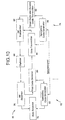
- the base station 14 transmits a pilot code while searching for the short code (step 200) .
- the subscriber unit 16 acquires the pilot code transmitted from the base station 14 (step 202) , starts transmitting a short code starting at a minimum power level P 0 which is guaranteed to be less than the required power, and quickly increases transmission power (step 204) .
- the base station 14 acquires the correct phase of the short code, transmits an indication of this detection, and begins searching for the access code (step 208) .
- the subscriber unit 16 Upon receiving the detection indication, the subscriber unit 16 ceases transmitting the short code and starts transmitting an access code.
- the subscriber unit 16 initiates a slow ramp-up of transmit power while sending the access code (step 210) .
- the base station 14 searches for the correct phase of the access code by searching only one phase out of each short code length portion of the access code (step 212) . If the base station 14 searches the phases of the access code up to the maximum round trip delay and has not detected the correct phase, the search is repeated by searching every phase (step 214) .
- the base station 14 Upon detection of the correct phase of the access code by the base station 14 , the base station 14 sends an acknowledgment to the subscriber unit 16 (step 216) . Reception of the acknowledgment by the subscriber unit 16 concludes the ramp-up process.
- a closed loop power control is established, and the subscriber unit 16 continues the call setup process by sending related call setup messages (step 218) .
Landscapes
- Computer Networks & Wireless Communication (AREA)
- Signal Processing (AREA)
- Engineering & Computer Science (AREA)
- Mobile Radio Communication Systems (AREA)
- Small-Scale Networks (AREA)
- Electrotherapy Devices (AREA)
- Control Of Ac Motors In General (AREA)
- Control Of Eletrric Generators (AREA)
- Remote Monitoring And Control Of Power-Distribution Networks (AREA)
- Communication Control (AREA)
- Prostheses (AREA)
- Television Receiver Circuits (AREA)
- Steering Control In Accordance With Driving Conditions (AREA)
- Supply And Distribution Of Alternating Current (AREA)
- Transmitters (AREA)
- Input Circuits Of Receivers And Coupling Of Receivers And Audio Equipment (AREA)
- Supply Devices, Intensifiers, Converters, And Telemotors (AREA)
- Selective Calling Equipment (AREA)
- Synchronisation In Digital Transmission Systems (AREA)
Priority Applications (12)
| Application Number | Priority Date | Filing Date | Title |
|---|---|---|---|
| EP03018061A EP1411646B1 (en) | 1996-06-27 | 1997-06-23 | A method of controlling initial power ramp-up in CDMA systems by using short codes |
| EP00111007A EP1037395B1 (en) | 1996-06-27 | 1997-06-23 | Device and method for communication between base station and subscriber unit in CDMA communication system |
| EP07009968.4A EP1814237B1 (en) | 1996-06-27 | 1997-06-23 | Device and method for communication between base station and subscriber unit in CDMA communication system |
| EP10182382.1A EP2271158A3 (en) | 1996-06-27 | 1997-06-23 | Device and method for communication between base station and subscriber unit in CDMA communication system |
| EP07009969A EP1814240B1 (en) | 1996-06-27 | 1997-06-23 | Subscriber unit and method for controlling transmission power during establishment of a channel in a CDMA communication system |
| EP07009972.6A EP1814243B9 (en) | 1996-06-27 | 1997-06-23 | Base station and subscriber unit in CDMA communication system |
| EP10182369.8A EP2271157A3 (en) | 1996-06-27 | 1997-06-23 | Device and method for communication between base station and subscriber unit in CDMA communication system |
| EP01124286A EP1172942B1 (en) | 1996-06-27 | 1997-06-23 | A method of controlling initial power ramp-up in CDMA systems by using short codes |
| EP04010946A EP1453221B1 (en) | 1996-06-27 | 1997-06-23 | Subscriber unit with controlled initial transmit power ramp up in CDMA communication system and related base station |
| EP07009971A EP1814242A3 (en) | 1996-06-27 | 1997-06-23 | Device and method for communication between base station and subscriber unit in CDMA communication system |
| EP07009970A EP1814241A3 (en) | 1996-06-27 | 1997-06-23 | Device and method for communication between base station and subscriber unit in CDMA communication system |
| HK04104376.2A HK1061479B (en) | 2004-06-16 | A method of controlling initial power ramp-up in cdma systems by using short codes |
Applications Claiming Priority (5)
| Application Number | Priority Date | Filing Date | Title |
|---|---|---|---|
| US08/670,162 US5841768A (en) | 1996-06-27 | 1996-06-27 | Method of controlling initial power ramp-up in CDMA systems by using short codes |
| US671068 | 1996-06-27 | ||
| US08/671,068 US5940382A (en) | 1996-06-27 | 1996-06-27 | Virtual locating of a fixed subscriber unit to reduce re-acquisition time |
| US670162 | 1996-06-27 | ||
| PCT/US1997/010754 WO1997050194A2 (en) | 1996-06-27 | 1997-06-23 | A method of controlling initial power ramp-up in cdma systems by using short codes |
Related Child Applications (5)
| Application Number | Title | Priority Date | Filing Date |
|---|---|---|---|
| EP07009968.4A Division EP1814237B1 (en) | 1996-06-27 | 1997-06-23 | Device and method for communication between base station and subscriber unit in CDMA communication system |
| EP10182369.8A Division EP2271157A3 (en) | 1996-06-27 | 1997-06-23 | Device and method for communication between base station and subscriber unit in CDMA communication system |
| EP00111007A Division EP1037395B1 (en) | 1996-06-27 | 1997-06-23 | Device and method for communication between base station and subscriber unit in CDMA communication system |
| EP10182382.1A Division EP2271158A3 (en) | 1996-06-27 | 1997-06-23 | Device and method for communication between base station and subscriber unit in CDMA communication system |
| EP01124286A Division EP1172942B1 (en) | 1996-06-27 | 1997-06-23 | A method of controlling initial power ramp-up in CDMA systems by using short codes |
Publications (2)
| Publication Number | Publication Date |
|---|---|
| EP0908021A2 EP0908021A2 (en) | 1999-04-14 |
| EP0908021B1 true EP0908021B1 (en) | 2002-06-05 |
Family
ID=27100263
Family Applications (12)
| Application Number | Title | Priority Date | Filing Date |
|---|---|---|---|
| EP97930175A Expired - Lifetime EP0908021B1 (en) | 1996-06-27 | 1997-06-23 | A method and network of controlling initial power ramp-up in cdma systems by using short codes |
| EP07009969A Expired - Lifetime EP1814240B1 (en) | 1996-06-27 | 1997-06-23 | Subscriber unit and method for controlling transmission power during establishment of a channel in a CDMA communication system |
| EP04010946A Expired - Lifetime EP1453221B1 (en) | 1996-06-27 | 1997-06-23 | Subscriber unit with controlled initial transmit power ramp up in CDMA communication system and related base station |
| EP07009971A Ceased EP1814242A3 (en) | 1996-06-27 | 1997-06-23 | Device and method for communication between base station and subscriber unit in CDMA communication system |
| EP01124286A Expired - Lifetime EP1172942B1 (en) | 1996-06-27 | 1997-06-23 | A method of controlling initial power ramp-up in CDMA systems by using short codes |
| EP00111007A Expired - Lifetime EP1037395B1 (en) | 1996-06-27 | 1997-06-23 | Device and method for communication between base station and subscriber unit in CDMA communication system |
| EP07009972.6A Expired - Lifetime EP1814243B9 (en) | 1996-06-27 | 1997-06-23 | Base station and subscriber unit in CDMA communication system |
| EP10182382.1A Withdrawn EP2271158A3 (en) | 1996-06-27 | 1997-06-23 | Device and method for communication between base station and subscriber unit in CDMA communication system |
| EP07009968.4A Expired - Lifetime EP1814237B1 (en) | 1996-06-27 | 1997-06-23 | Device and method for communication between base station and subscriber unit in CDMA communication system |
| EP03018061A Expired - Lifetime EP1411646B1 (en) | 1996-06-27 | 1997-06-23 | A method of controlling initial power ramp-up in CDMA systems by using short codes |
| EP07009970A Ceased EP1814241A3 (en) | 1996-06-27 | 1997-06-23 | Device and method for communication between base station and subscriber unit in CDMA communication system |
| EP10182369.8A Withdrawn EP2271157A3 (en) | 1996-06-27 | 1997-06-23 | Device and method for communication between base station and subscriber unit in CDMA communication system |
Family Applications After (11)
| Application Number | Title | Priority Date | Filing Date |
|---|---|---|---|
| EP07009969A Expired - Lifetime EP1814240B1 (en) | 1996-06-27 | 1997-06-23 | Subscriber unit and method for controlling transmission power during establishment of a channel in a CDMA communication system |
| EP04010946A Expired - Lifetime EP1453221B1 (en) | 1996-06-27 | 1997-06-23 | Subscriber unit with controlled initial transmit power ramp up in CDMA communication system and related base station |
| EP07009971A Ceased EP1814242A3 (en) | 1996-06-27 | 1997-06-23 | Device and method for communication between base station and subscriber unit in CDMA communication system |
| EP01124286A Expired - Lifetime EP1172942B1 (en) | 1996-06-27 | 1997-06-23 | A method of controlling initial power ramp-up in CDMA systems by using short codes |
| EP00111007A Expired - Lifetime EP1037395B1 (en) | 1996-06-27 | 1997-06-23 | Device and method for communication between base station and subscriber unit in CDMA communication system |
| EP07009972.6A Expired - Lifetime EP1814243B9 (en) | 1996-06-27 | 1997-06-23 | Base station and subscriber unit in CDMA communication system |
| EP10182382.1A Withdrawn EP2271158A3 (en) | 1996-06-27 | 1997-06-23 | Device and method for communication between base station and subscriber unit in CDMA communication system |
| EP07009968.4A Expired - Lifetime EP1814237B1 (en) | 1996-06-27 | 1997-06-23 | Device and method for communication between base station and subscriber unit in CDMA communication system |
| EP03018061A Expired - Lifetime EP1411646B1 (en) | 1996-06-27 | 1997-06-23 | A method of controlling initial power ramp-up in CDMA systems by using short codes |
| EP07009970A Ceased EP1814241A3 (en) | 1996-06-27 | 1997-06-23 | Device and method for communication between base station and subscriber unit in CDMA communication system |
| EP10182369.8A Withdrawn EP2271157A3 (en) | 1996-06-27 | 1997-06-23 | Device and method for communication between base station and subscriber unit in CDMA communication system |
Country Status (12)
| Country | Link |
|---|---|
| EP (12) | EP0908021B1 (es) |
| JP (22) | JP3683279B2 (es) |
| KR (21) | KR101029337B1 (es) |
| CN (6) | CN102083190B (es) |
| AT (6) | ATE281029T1 (es) |
| AU (1) | AU3406897A (es) |
| CA (10) | CA2413948C (es) |
| DE (8) | DE1172942T1 (es) |
| DK (7) | DK1814243T3 (es) |
| ES (8) | ES2398666T3 (es) |
| PT (1) | PT1411646E (es) |
| WO (1) | WO1997050194A2 (es) |
Families Citing this family (19)
| Publication number | Priority date | Publication date | Assignee | Title |
|---|---|---|---|---|
| JP2858052B2 (ja) | 1991-05-08 | 1999-02-17 | エー ヴェー メン ゲゼルシャフト ミット ベシュレンクテル ハフツング ウント コンパニー マシーネンファブリーク | 圧延顎により形作りを行なう機械に粗造りボルトを供給する装置 |
| DE1172942T1 (de) * | 1996-06-27 | 2003-03-06 | Interdigital Technology Corp., Wilmington | Ein Verfahren zum kontrollieren des Hochfahrens der Anfangssendeleistung in einem CDMA System unter Verwendung kurzer Kodes |
| EP1011211B1 (en) | 1997-04-17 | 2004-12-01 | NTT DoCoMo, Inc. | Receiver and method for coherent reception using received pilot symbols |
| DK1062749T3 (da) * | 1998-03-17 | 2002-05-06 | Interdigital Tech Corp | Modulær basisstation med variabel kommunikationskapacitet |
| US6414951B1 (en) | 1999-10-08 | 2002-07-02 | Interdigital Technology Corporation | Method for detecting short codes in CDMA systems |
| US7158563B2 (en) * | 2001-06-01 | 2007-01-02 | The Board Of Trustees Of The Leland Stanford Junior University | Dynamic digital communication system control |
| EP1411650B1 (en) * | 2001-07-24 | 2014-11-26 | NTT DoCoMo, Inc. | Transmission power control apparatus and method in a mobile communication system |
| GB2382746B (en) * | 2001-11-20 | 2005-12-14 | Ericsson Telefon Ab L M | Establishing radio communication channels |
| DE10204851B4 (de) * | 2002-02-06 | 2005-12-15 | Infineon Technologies Ag | Datenübertragungssystem mit einstellbarer Sendeleistung |
| US6876868B2 (en) | 2002-04-08 | 2005-04-05 | Motorola, Inc. | System and method for predictive transmit power control for mobile stations in a multiple access wireless communication system |
| EP1656746B1 (en) * | 2003-08-11 | 2009-03-04 | Koninklijke Philips Electronics N.V. | Power management in mobile terminals to allow transmission of ack/nack signals |
| WO2006023012A2 (en) * | 2004-08-24 | 2006-03-02 | Venkata Guruprasad | Distance division multiplexing |
| US20060262874A1 (en) * | 2005-05-17 | 2006-11-23 | Interdigital Technology Corporation | Method and apparatus for power control in a multiple antenna system |
| JP4835951B2 (ja) * | 2005-11-04 | 2011-12-14 | 日本電気株式会社 | 無線通信システムとその送信電力制御方法 |
| US8600370B2 (en) * | 2008-11-04 | 2013-12-03 | Huawei Technologies Co., Ltd. | Systems and methods for maintaining constant closed subscriber group cell reselection radius |
| JP5365583B2 (ja) * | 2010-06-04 | 2013-12-11 | 富士通株式会社 | 無線通信装置、送信電力制御方法および送信電力制御プログラム |
| DE102014119135A1 (de) | 2014-12-19 | 2016-06-23 | Sedac-Mecobel S.A. | Gelenkverbinder für eine Faltmechanik |
| WO2017103759A2 (en) * | 2015-12-16 | 2017-06-22 | Koninklijke Philips N.V. | Systems and methods for wireless communication for magnetic resonance imaging (mri) systems |
| CN106130573B (zh) * | 2016-08-25 | 2019-11-15 | 上海创远仪器技术股份有限公司 | NB-IoT导频信号发生装置的导频信号发生方法 |
Family Cites Families (18)
| Publication number | Priority date | Publication date | Assignee | Title |
|---|---|---|---|---|
| FR2498379A1 (fr) * | 1981-01-20 | 1982-07-23 | Thomson Csf | Dispositif d'orientation selon deux axes orthogonaux, utilisation dans une antenne hyperfrequence et antenne hyperfrequence comportant un tel dispositif |
| JPH02256331A (ja) * | 1989-03-29 | 1990-10-17 | Sharp Corp | 無線通信システム |
| US5056109A (en) | 1989-11-07 | 1991-10-08 | Qualcomm, Inc. | Method and apparatus for controlling transmission power in a cdma cellular mobile telephone system |
| US5265119A (en) * | 1989-11-07 | 1993-11-23 | Qualcomm Incorporated | Method and apparatus for controlling transmission power in a CDMA cellular mobile telephone system |
| JPH03231523A (ja) * | 1990-02-07 | 1991-10-15 | Nippon Telegr & Teleph Corp <Ntt> | 移動通信制御方式 |
| JPH05227124A (ja) * | 1992-02-10 | 1993-09-03 | Sharp Corp | 符号分割多元アクセス通信方式 |
| MX9301888A (es) * | 1992-04-10 | 1993-11-30 | Ericsson Telefon Ab L M | Acceso multiple de division de tiempo para acceso de un movil en un sistema de acceso multiple de division de codigo. |
| EP0565507A3 (en) * | 1992-04-10 | 1994-11-30 | Ericsson Ge Mobile Communicat | Power control for random access call set-up in a mobile telephone system |
| KR940012914A (ko) * | 1992-11-26 | 1994-06-24 | 정용문 | 코드분할 다중접속방식의 이동국 송신전력 제어방법 및 장치 |
| EP0639899B2 (en) * | 1993-03-05 | 2008-02-27 | Ntt Mobile Communications Network Inc. | Random access communication method by use of cdma, and system for mobile stations which use the method |
| JPH07170574A (ja) * | 1993-12-14 | 1995-07-04 | Uniden Corp | 接続制御方法及びそれを用いたコードレス電話機 |
| JPH07297776A (ja) * | 1994-04-22 | 1995-11-10 | Oki Electric Ind Co Ltd | 通信システム |
| US5604730A (en) * | 1994-07-25 | 1997-02-18 | Qualcomm Incorporated | Remote transmitter power control in a contention based multiple access system |
| US5528593A (en) * | 1994-09-30 | 1996-06-18 | Qualcomm Incorporated | Method and apparatus for controlling power in a variable rate communication system |
| US5528623A (en) * | 1994-10-26 | 1996-06-18 | American Wireless Corporation | Cordless telephone system having automatic control of transmitter power and frequency in response to changing conditions |
| ZA965340B (en) * | 1995-06-30 | 1997-01-27 | Interdigital Tech Corp | Code division multiple access (cdma) communication system |
| FI103082B1 (fi) * | 1996-05-27 | 1999-04-15 | Nokia Telecommunications Oy | Yhteydenmuodostusmenetelmä ja radiojärjestelmä |
| DE1172942T1 (de) * | 1996-06-27 | 2003-03-06 | Interdigital Technology Corp., Wilmington | Ein Verfahren zum kontrollieren des Hochfahrens der Anfangssendeleistung in einem CDMA System unter Verwendung kurzer Kodes |
-
1997
- 1997-06-23 DE DE1172942T patent/DE1172942T1/de active Pending
- 1997-06-23 KR KR1020097022914A patent/KR101029337B1/ko not_active Expired - Fee Related
- 1997-06-23 EP EP97930175A patent/EP0908021B1/en not_active Expired - Lifetime
- 1997-06-23 KR KR1020047016084A patent/KR100730014B1/ko not_active Expired - Lifetime
- 1997-06-23 CA CA002413948A patent/CA2413948C/en not_active Expired - Lifetime
- 1997-06-23 DK DK07009972.6T patent/DK1814243T3/da active
- 1997-06-23 EP EP07009969A patent/EP1814240B1/en not_active Expired - Lifetime
- 1997-06-23 AT AT00111007T patent/ATE281029T1/de not_active IP Right Cessation
- 1997-06-23 CN CN201010623780.7A patent/CN102083190B/zh not_active Expired - Lifetime
- 1997-06-23 CA CA2676866A patent/CA2676866C/en not_active Expired - Lifetime
- 1997-06-23 DE DE69735173T patent/DE69735173T2/de not_active Expired - Lifetime
- 1997-06-23 DE DE69731408T patent/DE69731408T2/de not_active Expired - Lifetime
- 1997-06-23 CN CNB021560080A patent/CN100550706C/zh not_active Expired - Lifetime
- 1997-06-23 DK DK07009968.4T patent/DK1814237T3/da active
- 1997-06-23 KR KR1020047015504A patent/KR100806652B1/ko not_active Expired - Fee Related
- 1997-06-23 CA CA2818770A patent/CA2818770C/en not_active Expired - Lifetime
- 1997-06-23 DE DE69739632T patent/DE69739632D1/de not_active Expired - Lifetime
- 1997-06-23 KR KR1020117029642A patent/KR101359854B1/ko not_active Expired - Fee Related
- 1997-06-23 AT AT03018061T patent/ATE317183T1/de not_active IP Right Cessation
- 1997-06-23 WO PCT/US1997/010754 patent/WO1997050194A2/en not_active Ceased
- 1997-06-23 EP EP04010946A patent/EP1453221B1/en not_active Expired - Lifetime
- 1997-06-23 KR KR1020107016973A patent/KR101079982B1/ko not_active Expired - Lifetime
- 1997-06-23 CA CA002259351A patent/CA2259351C/en not_active Expired - Lifetime
- 1997-06-23 KR KR1020117008235A patent/KR101229817B1/ko not_active Expired - Fee Related
- 1997-06-23 KR KR1020067015486A patent/KR100799533B1/ko not_active Expired - Fee Related
- 1997-06-23 ES ES07009972T patent/ES2398666T3/es not_active Expired - Lifetime
- 1997-06-23 CN CN200410047243.7A patent/CN1551527B/zh not_active Expired - Lifetime
- 1997-06-23 KR KR1020077020690A patent/KR100952881B1/ko not_active Expired - Fee Related
- 1997-06-23 CA CA002578405A patent/CA2578405C/en not_active Expired - Lifetime
- 1997-06-23 DK DK97930175T patent/DK0908021T3/da active
- 1997-06-23 DK DK01124286T patent/DK1172942T3/da active
- 1997-06-23 EP EP07009971A patent/EP1814242A3/en not_active Ceased
- 1997-06-23 AT AT97930175T patent/ATE218773T1/de not_active IP Right Cessation
- 1997-06-23 DK DK07009969.2T patent/DK1814240T3/da active
- 1997-06-23 EP EP01124286A patent/EP1172942B1/en not_active Expired - Lifetime
- 1997-06-23 CA CA002413954A patent/CA2413954C/en not_active Expired - Lifetime
- 1997-06-23 ES ES07009969T patent/ES2386279T3/es not_active Expired - Lifetime
- 1997-06-23 KR KR1020107016974A patent/KR101079947B1/ko not_active Expired - Lifetime
- 1997-06-23 EP EP00111007A patent/EP1037395B1/en not_active Expired - Lifetime
- 1997-06-23 KR KR1020057012347A patent/KR100918283B1/ko not_active Expired - Lifetime
- 1997-06-23 ES ES04010946T patent/ES2335881T3/es not_active Expired - Lifetime
- 1997-06-23 ES ES07009968T patent/ES2530373T3/es not_active Expired - Lifetime
- 1997-06-23 KR KR1020067015487A patent/KR100872110B1/ko not_active Expired - Lifetime
- 1997-06-23 EP EP07009972.6A patent/EP1814243B9/en not_active Expired - Lifetime
- 1997-06-23 EP EP10182382.1A patent/EP2271158A3/en not_active Withdrawn
- 1997-06-23 ES ES01124286T patent/ES2172489T3/es not_active Expired - Lifetime
- 1997-06-23 KR KR1020157004518A patent/KR20150034798A/ko not_active Abandoned
- 1997-06-23 AU AU34068/97A patent/AU3406897A/en not_active Abandoned
- 1997-06-23 DE DE1037395T patent/DE1037395T1/de active Pending
- 1997-06-23 JP JP50339098A patent/JP3683279B2/ja not_active Expired - Lifetime
- 1997-06-23 EP EP07009968.4A patent/EP1814237B1/en not_active Expired - Lifetime
- 1997-06-23 KR KR1020097013752A patent/KR100962621B1/ko not_active Expired - Lifetime
- 1997-06-23 DK DK00111007T patent/DK1037395T3/da active
- 1997-06-23 DE DE69713096T patent/DE69713096T2/de not_active Expired - Lifetime
- 1997-06-23 AT AT07009969T patent/ATE555630T1/de active
- 1997-06-23 CA CA002413937A patent/CA2413937C/en not_active Expired - Lifetime
- 1997-06-23 KR KR1020117029640A patent/KR101246134B1/ko not_active Expired - Fee Related
- 1997-06-23 ES ES97930175T patent/ES2139554T3/es not_active Expired - Lifetime
- 1997-06-23 CN CNB971958416A patent/CN1154253C/zh not_active Expired - Lifetime
- 1997-06-23 ES ES03018061T patent/ES2258190T3/es not_active Expired - Lifetime
- 1997-06-23 KR KR1020097004299A patent/KR100972803B1/ko not_active Expired - Lifetime
- 1997-06-23 ES ES00111007T patent/ES2154617T3/es not_active Expired - Lifetime
- 1997-06-23 PT PT03018061T patent/PT1411646E/pt unknown
- 1997-06-23 DK DK04010946.4T patent/DK1453221T3/da active
- 1997-06-23 CN CN2010106237898A patent/CN102083185B/zh not_active Expired - Lifetime
- 1997-06-23 KR KR1020057013853A patent/KR100985806B1/ko not_active Expired - Lifetime
- 1997-06-23 EP EP03018061A patent/EP1411646B1/en not_active Expired - Lifetime
- 1997-06-23 KR KR1020127027418A patent/KR101478890B1/ko not_active Expired - Lifetime
- 1997-06-23 KR KR1020057011698A patent/KR100799532B1/ko not_active Expired - Lifetime
- 1997-06-23 CA CA002413950A patent/CA2413950C/en not_active Expired - Lifetime
- 1997-06-23 DE DE0908021T patent/DE908021T1/de active Pending
- 1997-06-23 AT AT01124286T patent/ATE247343T1/de not_active IP Right Cessation
- 1997-06-23 AT AT04010946T patent/ATE446619T1/de not_active IP Right Cessation
- 1997-06-23 EP EP07009970A patent/EP1814241A3/en not_active Ceased
- 1997-06-23 CA CA002577444A patent/CA2577444C/en not_active Expired - Lifetime
- 1997-06-23 CN CN201210384407.XA patent/CN102932898B/zh not_active Expired - Lifetime
- 1997-06-23 EP EP10182369.8A patent/EP2271157A3/en not_active Withdrawn
- 1997-06-23 KR KR1020147011898A patent/KR20140066792A/ko not_active Abandoned
- 1997-06-23 DE DE69724163T patent/DE69724163T2/de not_active Expired - Lifetime
- 1997-06-23 KR KR1020117008234A patent/KR101282530B1/ko not_active Expired - Lifetime
- 1997-06-23 KR KR1020137019820A patent/KR101557208B1/ko not_active Expired - Lifetime
- 1997-06-23 CA CA2905192A patent/CA2905192A1/en not_active Expired - Lifetime
-
2002
- 2002-03-11 JP JP2002065420A patent/JP2002330475A/ja active Pending
-
2004
- 2004-09-17 JP JP2004271492A patent/JP3722443B2/ja not_active Expired - Lifetime
- 2004-10-15 JP JP2004301250A patent/JP4402561B2/ja not_active Expired - Lifetime
-
2005
- 2005-07-25 JP JP2005214039A patent/JP4085104B2/ja not_active Expired - Fee Related
- 2005-09-30 JP JP2005286995A patent/JP2006109473A/ja active Pending
-
2006
- 2006-09-11 JP JP2006245565A patent/JP4119464B2/ja not_active Expired - Lifetime
-
2007
- 2007-05-15 JP JP2007129812A patent/JP4200179B2/ja not_active Expired - Lifetime
- 2007-05-15 JP JP2007129813A patent/JP4117333B2/ja not_active Expired - Fee Related
- 2007-05-15 JP JP2007129814A patent/JP4200180B2/ja not_active Expired - Lifetime
-
2008
- 2008-07-22 JP JP2008189114A patent/JP2008312238A/ja active Pending
-
2009
- 2009-02-13 JP JP2009031953A patent/JP2009147964A/ja active Pending
- 2009-08-10 JP JP2009185680A patent/JP4834760B2/ja not_active Expired - Lifetime
-
2010
- 2010-03-08 JP JP2010050879A patent/JP5055396B2/ja not_active Expired - Lifetime
- 2010-04-08 JP JP2010089693A patent/JP4834777B2/ja not_active Expired - Lifetime
- 2010-04-08 JP JP2010089687A patent/JP5061216B2/ja not_active Expired - Lifetime
-
2011
- 2011-07-07 JP JP2011151217A patent/JP5592845B2/ja not_active Expired - Lifetime
- 2011-07-07 JP JP2011151218A patent/JP5059217B2/ja not_active Expired - Lifetime
-
2012
- 2012-12-26 JP JP2012282176A patent/JP5592930B2/ja not_active Expired - Lifetime
- 2012-12-26 JP JP2012282175A patent/JP5592929B2/ja not_active Expired - Lifetime
-
2013
- 2013-12-25 JP JP2013267459A patent/JP2014090485A/ja not_active Ceased
-
2014
- 2014-06-11 JP JP2014120788A patent/JP2014207694A/ja active Pending
Also Published As
Similar Documents
| Publication | Publication Date | Title |
|---|---|---|
| US5841768A (en) | Method of controlling initial power ramp-up in CDMA systems by using short codes | |
| EP0908021B1 (en) | A method and network of controlling initial power ramp-up in cdma systems by using short codes | |
| HK1019271B (en) | A method and network of controlling initial power ramp-up in cdma systems by using short codes |
Legal Events
| Date | Code | Title | Description |
|---|---|---|---|
| PUAI | Public reference made under article 153(3) epc to a published international application that has entered the european phase |
Free format text: ORIGINAL CODE: 0009012 |
|
| 17P | Request for examination filed |
Effective date: 19981228 |
|
| AK | Designated contracting states |
Kind code of ref document: A2 Designated state(s): AT BE CH DE DK ES FI FR GB GR IE IT LI LU MC NL PT SE |
|
| 17Q | First examination report despatched |
Effective date: 19990623 |
|
| EL | Fr: translation of claims filed | ||
| DET | De: translation of patent claims | ||
| REG | Reference to a national code |
Ref country code: ES Ref legal event code: BA2A Ref document number: 2139554 Country of ref document: ES Kind code of ref document: T1 |
|
| GRAG | Despatch of communication of intention to grant |
Free format text: ORIGINAL CODE: EPIDOS AGRA |
|
| RTI1 | Title (correction) |
Free format text: A METHOD AND NETWORK OF CONTROLLING INITIAL POWER RAMP-UP IN CDMA SYSTEMS BY USING SHORT CODES |
|
| GRAG | Despatch of communication of intention to grant |
Free format text: ORIGINAL CODE: EPIDOS AGRA |
|
| GRAH | Despatch of communication of intention to grant a patent |
Free format text: ORIGINAL CODE: EPIDOS IGRA |
|
| GRAH | Despatch of communication of intention to grant a patent |
Free format text: ORIGINAL CODE: EPIDOS IGRA |
|
| GRAA | (expected) grant |
Free format text: ORIGINAL CODE: 0009210 |
|
| AK | Designated contracting states |
Kind code of ref document: B1 Designated state(s): AT BE CH DE DK ES FI FR GB GR IE IT LI LU MC NL PT SE |
|
| PG25 | Lapsed in a contracting state [announced via postgrant information from national office to epo] |
Ref country code: LI Free format text: LAPSE BECAUSE OF FAILURE TO SUBMIT A TRANSLATION OF THE DESCRIPTION OR TO PAY THE FEE WITHIN THE PRESCRIBED TIME-LIMIT Effective date: 20020605 Ref country code: GR Free format text: LAPSE BECAUSE OF FAILURE TO SUBMIT A TRANSLATION OF THE DESCRIPTION OR TO PAY THE FEE WITHIN THE PRESCRIBED TIME-LIMIT Effective date: 20020605 Ref country code: CH Free format text: LAPSE BECAUSE OF FAILURE TO SUBMIT A TRANSLATION OF THE DESCRIPTION OR TO PAY THE FEE WITHIN THE PRESCRIBED TIME-LIMIT Effective date: 20020605 Ref country code: BE Free format text: LAPSE BECAUSE OF FAILURE TO SUBMIT A TRANSLATION OF THE DESCRIPTION OR TO PAY THE FEE WITHIN THE PRESCRIBED TIME-LIMIT Effective date: 20020605 Ref country code: AT Free format text: LAPSE BECAUSE OF FAILURE TO SUBMIT A TRANSLATION OF THE DESCRIPTION OR TO PAY THE FEE WITHIN THE PRESCRIBED TIME-LIMIT Effective date: 20020605 |
|
| REF | Corresponds to: |
Ref document number: 218773 Country of ref document: AT Date of ref document: 20020615 Kind code of ref document: T |
|
| REG | Reference to a national code |
Ref country code: GB Ref legal event code: FG4D |
|
| REG | Reference to a national code |
Ref country code: CH Ref legal event code: EP |
|
| PGFP | Annual fee paid to national office [announced via postgrant information from national office to epo] |
Ref country code: AT Payment date: 20020627 Year of fee payment: 6 |
|
| PGFP | Annual fee paid to national office [announced via postgrant information from national office to epo] |
Ref country code: MC Payment date: 20020628 Year of fee payment: 6 |
|
| PGFP | Annual fee paid to national office [announced via postgrant information from national office to epo] |
Ref country code: CH Payment date: 20020702 Year of fee payment: 6 |
|
| PGFP | Annual fee paid to national office [announced via postgrant information from national office to epo] |
Ref country code: LU Payment date: 20020708 Year of fee payment: 6 |
|
| REG | Reference to a national code |
Ref country code: IE Ref legal event code: FG4D |
|
| REF | Corresponds to: |
Ref document number: 69713096 Country of ref document: DE Date of ref document: 20020711 |
|
| PGFP | Annual fee paid to national office [announced via postgrant information from national office to epo] |
Ref country code: BE Payment date: 20020821 Year of fee payment: 6 |
|
| PG25 | Lapsed in a contracting state [announced via postgrant information from national office to epo] |
Ref country code: PT Free format text: LAPSE BECAUSE OF FAILURE TO SUBMIT A TRANSLATION OF THE DESCRIPTION OR TO PAY THE FEE WITHIN THE PRESCRIBED TIME-LIMIT Effective date: 20020905 |
|
| REG | Reference to a national code |
Ref country code: DK Ref legal event code: T3 |
|
| ET | Fr: translation filed | ||
| REG | Reference to a national code |
Ref country code: CH Ref legal event code: PL |
|
| REG | Reference to a national code |
Ref country code: ES Ref legal event code: FG2A Ref document number: 2139554 Country of ref document: ES Kind code of ref document: T3 |
|
| PLBE | No opposition filed within time limit |
Free format text: ORIGINAL CODE: 0009261 |
|
| STAA | Information on the status of an ep patent application or granted ep patent |
Free format text: STATUS: NO OPPOSITION FILED WITHIN TIME LIMIT |
|
| 26N | No opposition filed |
Effective date: 20030306 |
|
| PG25 | Lapsed in a contracting state [announced via postgrant information from national office to epo] |
Ref country code: LU Free format text: LAPSE BECAUSE OF NON-PAYMENT OF DUE FEES Effective date: 20030623 |
|
| PG25 | Lapsed in a contracting state [announced via postgrant information from national office to epo] |
Ref country code: MC Free format text: LAPSE BECAUSE OF NON-PAYMENT OF DUE FEES Effective date: 20030630 |
|
| REG | Reference to a national code |
Ref country code: FR Ref legal event code: PLFP Year of fee payment: 20 |
|
| PGFP | Annual fee paid to national office [announced via postgrant information from national office to epo] |
Ref country code: NL Payment date: 20160525 Year of fee payment: 20 |
|
| PGFP | Annual fee paid to national office [announced via postgrant information from national office to epo] |
Ref country code: GB Payment date: 20160527 Year of fee payment: 20 Ref country code: ES Payment date: 20160525 Year of fee payment: 20 Ref country code: FI Payment date: 20160524 Year of fee payment: 20 Ref country code: DE Payment date: 20160524 Year of fee payment: 20 Ref country code: IE Payment date: 20160524 Year of fee payment: 20 |
|
| PGFP | Annual fee paid to national office [announced via postgrant information from national office to epo] |
Ref country code: DK Payment date: 20160524 Year of fee payment: 20 Ref country code: FR Payment date: 20160526 Year of fee payment: 20 Ref country code: IT Payment date: 20160525 Year of fee payment: 20 Ref country code: SE Payment date: 20160527 Year of fee payment: 20 |
|
| REG | Reference to a national code |
Ref country code: DE Ref legal event code: R071 Ref document number: 69713096 Country of ref document: DE |
|
| REG | Reference to a national code |
Ref country code: DK Ref legal event code: EUP Effective date: 20170623 |
|
| REG | Reference to a national code |
Ref country code: NL Ref legal event code: MK Effective date: 20170622 |
|
| REG | Reference to a national code |
Ref country code: GB Ref legal event code: PE20 Expiry date: 20170622 |
|
| REG | Reference to a national code |
Ref country code: IE Ref legal event code: MK9A |
|
| PG25 | Lapsed in a contracting state [announced via postgrant information from national office to epo] |
Ref country code: GB Free format text: LAPSE BECAUSE OF EXPIRATION OF PROTECTION Effective date: 20170622 |
|
| REG | Reference to a national code |
Ref country code: SE Ref legal event code: EUG |
|
| PG25 | Lapsed in a contracting state [announced via postgrant information from national office to epo] |
Ref country code: IE Free format text: LAPSE BECAUSE OF EXPIRATION OF PROTECTION Effective date: 20170623 |
|
| REG | Reference to a national code |
Ref country code: ES Ref legal event code: FD2A Effective date: 20180508 |
|
| PG25 | Lapsed in a contracting state [announced via postgrant information from national office to epo] |
Ref country code: ES Free format text: LAPSE BECAUSE OF EXPIRATION OF PROTECTION Effective date: 20170624 |