EP2271158A2 - Device and method for communication between base station and subscriber unit in CDMA communication system - Google Patents
Device and method for communication between base station and subscriber unit in CDMA communication system Download PDFInfo
- Publication number
- EP2271158A2 EP2271158A2 EP10182382A EP10182382A EP2271158A2 EP 2271158 A2 EP2271158 A2 EP 2271158A2 EP 10182382 A EP10182382 A EP 10182382A EP 10182382 A EP10182382 A EP 10182382A EP 2271158 A2 EP2271158 A2 EP 2271158A2
- Authority
- EP
- European Patent Office
- Prior art keywords
- subscriber unit
- type
- base station
- code
- unit according
- Prior art date
- Legal status (The legal status is an assumption and is not a legal conclusion. Google has not performed a legal analysis and makes no representation as to the accuracy of the status listed.)
- Withdrawn
Links
- 238000000034 method Methods 0.000 title claims abstract description 47
- 238000004891 communication Methods 0.000 title claims description 91
- 230000005540 biological transmission Effects 0.000 claims description 70
- 230000004044 response Effects 0.000 claims description 6
- 230000007480 spreading Effects 0.000 description 40
- 230000008569 process Effects 0.000 description 22
- 238000001514 detection method Methods 0.000 description 21
- 238000010586 diagram Methods 0.000 description 17
- 238000001228 spectrum Methods 0.000 description 10
- 238000012790 confirmation Methods 0.000 description 9
- 230000001934 delay Effects 0.000 description 9
- 230000000875 corresponding effect Effects 0.000 description 8
- 230000001360 synchronised effect Effects 0.000 description 6
- 230000000737 periodic effect Effects 0.000 description 5
- 230000011664 signaling Effects 0.000 description 5
- 230000003044 adaptive effect Effects 0.000 description 4
- 230000001276 controlling effect Effects 0.000 description 4
- 238000012545 processing Methods 0.000 description 4
- 238000012360 testing method Methods 0.000 description 4
- 108010003272 Hyaluronate lyase Proteins 0.000 description 3
- 230000008901 benefit Effects 0.000 description 3
- 230000008859 change Effects 0.000 description 2
- 230000000977 initiatory effect Effects 0.000 description 2
- 230000002441 reversible effect Effects 0.000 description 2
- 230000032683 aging Effects 0.000 description 1
- 230000015556 catabolic process Effects 0.000 description 1
- 230000001413 cellular effect Effects 0.000 description 1
- 230000002596 correlated effect Effects 0.000 description 1
- 238000006731 degradation reaction Methods 0.000 description 1
- 230000003111 delayed effect Effects 0.000 description 1
- 230000000694 effects Effects 0.000 description 1
- 238000005562 fading Methods 0.000 description 1
- 230000036039 immunity Effects 0.000 description 1
- 238000012423 maintenance Methods 0.000 description 1
- 238000005259 measurement Methods 0.000 description 1
- 238000011084 recovery Methods 0.000 description 1
- 230000009467 reduction Effects 0.000 description 1
- 238000000411 transmission spectrum Methods 0.000 description 1
Images


Classifications
-
- H—ELECTRICITY
- H04—ELECTRIC COMMUNICATION TECHNIQUE
- H04B—TRANSMISSION
- H04B1/00—Details of transmission systems, not covered by a single one of groups H04B3/00 - H04B13/00; Details of transmission systems not characterised by the medium used for transmission
- H04B1/69—Spread spectrum techniques
- H04B1/707—Spread spectrum techniques using direct sequence modulation
-
- H—ELECTRICITY
- H04—ELECTRIC COMMUNICATION TECHNIQUE
- H04W—WIRELESS COMMUNICATION NETWORKS
- H04W52/00—Power management, e.g. TPC [Transmission Power Control], power saving or power classes
- H04W52/04—TPC
- H04W52/30—TPC using constraints in the total amount of available transmission power
- H04W52/36—TPC using constraints in the total amount of available transmission power with a discrete range or set of values, e.g. step size, ramping or offsets
- H04W52/362—Aspects of the step size
-
- H—ELECTRICITY
- H04—ELECTRIC COMMUNICATION TECHNIQUE
- H04W—WIRELESS COMMUNICATION NETWORKS
- H04W52/00—Power management, e.g. TPC [Transmission Power Control], power saving or power classes
- H04W52/04—TPC
- H04W52/54—Signalisation aspects of the TPC commands, e.g. frame structure
- H04W52/60—Signalisation aspects of the TPC commands, e.g. frame structure using different transmission rates for TPC commands
-
- H—ELECTRICITY
- H04—ELECTRIC COMMUNICATION TECHNIQUE
- H04B—TRANSMISSION
- H04B1/00—Details of transmission systems, not covered by a single one of groups H04B3/00 - H04B13/00; Details of transmission systems not characterised by the medium used for transmission
- H04B1/69—Spread spectrum techniques
- H04B1/707—Spread spectrum techniques using direct sequence modulation
- H04B1/7073—Synchronisation aspects
- H04B1/7075—Synchronisation aspects with code phase acquisition
- H04B1/70751—Synchronisation aspects with code phase acquisition using partial detection
- H04B1/70753—Partial phase search
-
- H—ELECTRICITY
- H04—ELECTRIC COMMUNICATION TECHNIQUE
- H04B—TRANSMISSION
- H04B1/00—Details of transmission systems, not covered by a single one of groups H04B3/00 - H04B13/00; Details of transmission systems not characterised by the medium used for transmission
- H04B1/69—Spread spectrum techniques
- H04B1/707—Spread spectrum techniques using direct sequence modulation
- H04B1/7073—Synchronisation aspects
- H04B1/7075—Synchronisation aspects with code phase acquisition
- H04B1/70755—Setting of lock conditions, e.g. threshold
-
- H—ELECTRICITY
- H04—ELECTRIC COMMUNICATION TECHNIQUE
- H04B—TRANSMISSION
- H04B1/00—Details of transmission systems, not covered by a single one of groups H04B3/00 - H04B13/00; Details of transmission systems not characterised by the medium used for transmission
- H04B1/69—Spread spectrum techniques
- H04B1/707—Spread spectrum techniques using direct sequence modulation
- H04B1/7073—Synchronisation aspects
- H04B1/7075—Synchronisation aspects with code phase acquisition
- H04B1/70758—Multimode search, i.e. using multiple search strategies
-
- H—ELECTRICITY
- H04—ELECTRIC COMMUNICATION TECHNIQUE
- H04B—TRANSMISSION
- H04B1/00—Details of transmission systems, not covered by a single one of groups H04B3/00 - H04B13/00; Details of transmission systems not characterised by the medium used for transmission
- H04B1/69—Spread spectrum techniques
- H04B1/707—Spread spectrum techniques using direct sequence modulation
- H04B1/7073—Synchronisation aspects
- H04B1/7075—Synchronisation aspects with code phase acquisition
- H04B1/708—Parallel implementation
-
- H—ELECTRICITY
- H04—ELECTRIC COMMUNICATION TECHNIQUE
- H04L—TRANSMISSION OF DIGITAL INFORMATION, e.g. TELEGRAPHIC COMMUNICATION
- H04L1/00—Arrangements for detecting or preventing errors in the information received
- H04L1/12—Arrangements for detecting or preventing errors in the information received by using return channel
- H04L1/16—Arrangements for detecting or preventing errors in the information received by using return channel in which the return channel carries supervisory signals, e.g. repetition request signals
- H04L1/18—Automatic repetition systems, e.g. Van Duuren systems
- H04L1/1812—Hybrid protocols; Hybrid automatic repeat request [HARQ]
-
- H—ELECTRICITY
- H04—ELECTRIC COMMUNICATION TECHNIQUE
- H04W—WIRELESS COMMUNICATION NETWORKS
- H04W52/00—Power management, e.g. TPC [Transmission Power Control], power saving or power classes
- H04W52/04—TPC
- H04W52/30—TPC using constraints in the total amount of available transmission power
- H04W52/36—TPC using constraints in the total amount of available transmission power with a discrete range or set of values, e.g. step size, ramping or offsets
- H04W52/367—Power values between minimum and maximum limits, e.g. dynamic range
-
- H—ELECTRICITY
- H04—ELECTRIC COMMUNICATION TECHNIQUE
- H04W—WIRELESS COMMUNICATION NETWORKS
- H04W52/00—Power management, e.g. TPC [Transmission Power Control], power saving or power classes
- H04W52/04—TPC
- H04W52/38—TPC being performed in particular situations
- H04W52/50—TPC being performed in particular situations at the moment of starting communication in a multiple access environment
-
- H—ELECTRICITY
- H04—ELECTRIC COMMUNICATION TECHNIQUE
- H04W—WIRELESS COMMUNICATION NETWORKS
- H04W88/00—Devices specially adapted for wireless communication networks, e.g. terminals, base stations or access point devices
- H04W88/02—Terminal devices
-
- H—ELECTRICITY
- H04—ELECTRIC COMMUNICATION TECHNIQUE
- H04B—TRANSMISSION
- H04B1/00—Details of transmission systems, not covered by a single one of groups H04B3/00 - H04B13/00; Details of transmission systems not characterised by the medium used for transmission
- H04B1/69—Spread spectrum techniques
- H04B1/707—Spread spectrum techniques using direct sequence modulation
- H04B1/7073—Synchronisation aspects
- H04B1/7075—Synchronisation aspects with code phase acquisition
- H04B1/7077—Multi-step acquisition, e.g. multi-dwell, coarse-fine or validation
-
- H—ELECTRICITY
- H04—ELECTRIC COMMUNICATION TECHNIQUE
- H04B—TRANSMISSION
- H04B2201/00—Indexing scheme relating to details of transmission systems not covered by a single group of H04B3/00 - H04B13/00
- H04B2201/69—Orthogonal indexing scheme relating to spread spectrum techniques in general
- H04B2201/707—Orthogonal indexing scheme relating to spread spectrum techniques in general relating to direct sequence modulation
- H04B2201/70701—Orthogonal indexing scheme relating to spread spectrum techniques in general relating to direct sequence modulation featuring pilot assisted reception
-
- H—ELECTRICITY
- H04—ELECTRIC COMMUNICATION TECHNIQUE
- H04B—TRANSMISSION
- H04B2201/00—Indexing scheme relating to details of transmission systems not covered by a single group of H04B3/00 - H04B13/00
- H04B2201/69—Orthogonal indexing scheme relating to spread spectrum techniques in general
- H04B2201/707—Orthogonal indexing scheme relating to spread spectrum techniques in general relating to direct sequence modulation
- H04B2201/70702—Intercell-related aspects
-
- H—ELECTRICITY
- H04—ELECTRIC COMMUNICATION TECHNIQUE
- H04B—TRANSMISSION
- H04B2201/00—Indexing scheme relating to details of transmission systems not covered by a single group of H04B3/00 - H04B13/00
- H04B2201/69—Orthogonal indexing scheme relating to spread spectrum techniques in general
- H04B2201/707—Orthogonal indexing scheme relating to spread spectrum techniques in general relating to direct sequence modulation
- H04B2201/70703—Orthogonal indexing scheme relating to spread spectrum techniques in general relating to direct sequence modulation using multiple or variable rates
-
- H—ELECTRICITY
- H04—ELECTRIC COMMUNICATION TECHNIQUE
- H04B—TRANSMISSION
- H04B2201/00—Indexing scheme relating to details of transmission systems not covered by a single group of H04B3/00 - H04B13/00
- H04B2201/69—Orthogonal indexing scheme relating to spread spectrum techniques in general
- H04B2201/707—Orthogonal indexing scheme relating to spread spectrum techniques in general relating to direct sequence modulation
- H04B2201/70707—Efficiency-related aspects
- H04B2201/7071—Efficiency-related aspects with dynamic control of receiver resources
Definitions
- the present invention relates generally to CDMA communication systems. More specifically, the present invention relates to a CDMA communication system which utilizes the transmission of short codes from subscriber units to a base station to reduce the time required for the base station to detect the signal from a subscriber unit. The improved detection time allows a faster ramp-up of the initial transmit power from the subscriber units while reducing the unnecessary power overshoot.
- Wireless communication systems are being utilized in a variety of applications where land line based systems are impractical or impossible to use.
- Applications of wireless communications include cellular phone communications, communications in remote locations, and temporary communications for disaster recovery.
- Wireless communication systems have also become an economically viable alternative to replacing aging telephone lines and outdated' telephone equipment.
- the portion of the RF spectrum available for use by wireless communication systems is a critical resource.
- the RF spectrum must be shared among all commercial, governmental and military applications. There is a constant desire to improve the efficiency of wireless communication systems in order to increase system capacity.
- CDMA wireless communication systems have shown particular promise in this area. Although more traditional time division multiple access (TDMA) and frequency division multiple access (FDMA) systems have improved using the latest technological advances, CDMA systems, in particular Broadband Code Division Multiple Access TM (B-CDMA TM ) systems, have significant advantages over TDMA and FDMA systems. This efficiency is due to the improved coding and modulation density, interference rejection and multipath tolerance of B-CDMA TM systems, as well as reuse of the same spectrum in every communication cell. The format of CDMA communication signals also makes it extremely difficult to intercept calls, thereby ensuring greater privacy for callers and providing greater immunity against fraud.
- TDMA time division multiple access
- FDMA frequency division multiple access
- a CDMA system In a CDMA system, the same portion of the frequency spectrum is used for communication by all subscriber units.
- Each subscriber unit's baseband data signal is multiplied by a code sequence, called the “spreading code”, which has a much higher rate than the data.
- the ratio of the spreading code rate to the data symbol rate is called the “spreading factor” or the “processing gain”.
- This coding results in a much wider transmission spectrum than the spectrum of the baseband data signal, hence the technique is called “spread spectrum”.
- Subscriber units and their communications can be discriminated by assigning a unique spreading code to each communication link which is called a CDMA channel. Since all communications are sent over the same frequency band, each CDMA communication overlaps communications from other subscriber units and noise-related signals in both frequency and time.
- the control of transmission power is particularly critical when a subscriber unit is attempting to initiate communications with a base station and a power control loop has not yet been established.
- the transmission power required from a subscriber unit changes continuously as a function of the propagation loss, interference from other subscribers, channel noise, fading and other channel characteristics. Therefore, a subscriber unit does not know the power level at which it should start transmitting. If the subscriber unit begins transmitting at a power level that is too high, it may interfere with the communications of other subscriber units and may even terminate the communications of other subscriber units. If the initial transmission power level is too low, the subscriber unit will not be detected by the base station and a communication link will not be established.
- U.S. Patent No. 5,056,109 discloses a transmission power control system wherein the transmission power of the subscriber unit is based upon periodic signal measurements from both the subscriber unit and the base station.
- the base station transmits a pilot signal to all subscriber units which analyze the received pilot signal, estimate the power loss in the transmitted signal and adjust their transmission power accordingly.
- Each subscriber unit includes a non-linear loss output filter which prevents sudden increases in power which would cause interference to other subscriber units. This method is too complex to permit a base station to quickly acquire a subscriber unit while limiting the interference to other subscriber units.
- EP 0 565 507 A2 discloses a system for minimizing interference between two radio stations at the initiation of radio communications.
- a mobile station initiates a low level access signal and incrementally increases the transmission power level until the base station detects the signal. Once detected, the power level of the message is maintained at the detected level so that the signal interference is avoided.
- EP 0 565 507 A2 also discloses a method for synchronizing random access communications between mobile stations and the base station despite the variations in the distance between them.
- the present invention comprises a novel method of controlling transmission power during the establishment of a channel in a CDMA communication system by utilizing the transmission of a short code from a subscriber unit to a base station during initial power ramp-up.
- the short code is a sequence for detection by the base station which has a much shorter period than a conventional spreading code.
- the ramp-up starts from a power level that is guaranteed to be lower than the required power level for detection by the base station.
- the subscriber unit quickly increases transmission power while repeatedly transmitting the short code until the signal is detected by the base station. Once the base station detects the short code, it sends an indication to the subscriber unit to cease increasing transmission power.
- the use of short codes limits power overshoot and interference to other subscriber stations and permits the base station to quickly synchronize to the spreading code used by the subscriber unit.
- the communication network 10 generally comprises one or more base stations 14, each of which is in wireless communication with a plurality of subscriber units 16, which may be fixed or mobile. Each subscriber unit 16 communicates with either the closest base station 14 or the base station 14 which provides the strongest communication signal.
- the base stations 14 also communicate with a base station controller 20, which coordinates communications among base stations 14.
- the communication network 10 may also be connected to a public switched telephone network (PSTN) 22, wherein the base station controller 20 also coordinates communications between the base stations 14 and the PSTN 22.
- PSTN public switched telephone network
- each base station 14 communicates with the base station controller 20 over a wireless link, although a land line may also be provided. A land line is particularly applicable when a base station 14 is in close proximity to the base station controller 20.
- the base station controller 20 performs several functions. Primarily, the base station controller 20 provides all of the operations, administrative and maintenance (OA&M) signaling associated with establishing and maintaining all of the wireless communications between the subscriber units 16, the base stations 14, and the base station controller 20.
- the base station controller 20 also provides an interface between the wireless communication system 10 and the PSTN 22. This interface includes multiplexing and demultiplexing of the communication signals that enter and leave the system 10 via the base station controller 20.
- the wireless communication system 10 is shown employing antennas to transmit RF signals, one skilled in the art should recognize that communications may be accomplished via microwave or satellite uplinks. Additionally, the functions of the base station controller 20 may be combined with a base station 14 to form a "master base station".
- a two-way communication channel (link) 18 comprises a signal transmitted 20 (Tx) from the base station 14 to the subscriber unit 16 and a signal received 22 (Rx) by the base station 14 from the subscriber unit 16.
- the Tx signal 20 is transmitted from the base station 14 and is received by the subscriber unit 16 after a propagation delay ⁇ t.
- the Rx 22 signal originates at the subscriber unit 16 and terminates at the base station 14 after a further propagation delay ⁇ t.
- the round trip propagation delay is 2 ⁇ t.
- the base station 14 has an operating range of approximately 30 kilometers.
- the round trip propagation delay 24 associated with a subscriber unit 16 at the maximum operating range is 200 microseconds.
- the present invention is directed to initial power ramp-up and synchronization during the establishment of a communication channel.
- the base station 14 continuously transmits a pilot code 40 to all of the subscriber units 16 located within the transmitting range of the base station 14.
- the pilot code 40 is a spreading code which carries no data bits.
- the pilot code 40 is used for subscriber unit 16 acquisition and synchronization, as well as for determining the parameters of the adaptive matched filter used in the receiver.
- the subscriber unit 16 must acquire the pilot code 40 transmitted by the base station 14 before it can receive or transmit any data. Acquisition is the process whereby the subscriber unit 16 aligns its locally generated spreading code with the received pilot code 40. The subscriber unit 16 searches through all of the possible phases of the received pilot code 40 until it detects the correct phase, (the beginning of the pilot code 40).
- the subscriber unit 16 then synchronizes its transmit spreading code to the received pilot code 40 by aligning the beginning of its transmit spreading code to the beginning of the pilot code 40.
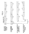
- receive and transmit synchronization One implication of this receive and transmit synchronization is that the subscriber unit 16 introduces no additional delay as far as the phase of the spreading codes are concerned. Accordingly, as shown in Figure 3 , the relative delay between the pilot code 40 transmitted from the base station 14 and the subscriber unit's transmit spreading code 42 received at the base station 14 is 2 ⁇ t, which is solely due to the round trip propagation delay.
- the pilot code is 29,877,120 chips in length and takes approximately 2 to 5 seconds to transmit, depending on the spreading factor.
- the length of the pilot code 40 was chosen to be a multiple of the data symbol no matter what kind of data rate or bandwidth is used. As is well known by those of skill in the art, a longer pilot code 40 has better randomness properties and the frequency response of the pilot code 40 is more uniform. Additionally, a longer pilot code 40 provides low channel cross correlation, thus increasing the capacity of the system 10 to support more subscriber units 16 with less interference. The use of a long pilot code 40 also supports a greater number of random short codes. For synchronization purposes, the pilot code 40 is chosen to have the same period as all of the other spreading codes used by the system 10. Thus, once a subscriber unit 16 acquires the pilot code 40, it is synchronized to all other signals transmitted from the base station 14.
- the subscriber unit 16 During idle periods, when a call is not in progress or pending, the subscriber unit 16 remains synchronized to the base station 14 by periodically reacquiring the pilot code 40. This is necessary for the subscriber unit 16 to receive and demodulate any downlink transmissions, in particular paging messages which indicate incoming calls.
- the base station 14 When a communication link is desired, the base station 14 must acquire the signal transmitted from the subscriber unit 16 before it can demodulate the data. The subscriber unit 16 must transmit an uplink signal for acquisition by the base station 14 to begin establishing the two-way communication link.
- a critical parameter in this procedure is the transmission power level of the subscriber unit 16. A transmission power level that is too high can impair communications in the whole service area, whereas a transmission power level that is too low can prevent the base station 14 from detecting the uplink signal.
- the subscriber unit 16 starts transmitting at a power level guaranteed to be lower than what is required and increases transmission power output until the correct power level is achieved. This avoids sudden introduction of a strong interference, hence improving system 10 capacity.
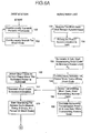
- the base station 14 begins by continuously transmitting a periodic pilot code 40 to all subscriber units 16 located within the operating range of the base station 14 (step 100). As the base station 14 transmits the pilot code 40 (step 100), the base station 14 searches (step 101) for an "access code" 42 transmitted by a subscriber unit 16.
- the access code 42 is a known spreading code transmitted from a subscriber unit 16 to the base station 14 during initiation of communications and power ramp-up.
- the base station 14 must search through all possible phases (time shifts) of the access code 42 transmitted from the subscriber unit 16 in order to find the correct phase. This is called the "acquisition” or the "detection” process (step 101). The longer the access code 42, the longer it takes for the base station 14 to search through the phases and acquire the correct phase.
- the relative delay between signals transmitted from the base station 14 and return signals received at the base station 14 corresponds to the round trip propagation delay 2 ⁇ t.
- the maximum delay occurs at the maximum operating range of the base station 14, known as the cell boundary. Accordingly, the base station 14 must search up to as many code phases as there are in the maximum round trip propagation delay, which is typically less code phases than there are in a code period.
- the ratio L Rc/Rb is called the spreading factor or the processing gain.
- the cell boundary radius is 30 km, which corresponds to approximately between 1000 and 2500 code phases in the maximum round trip delay, depending on the processing gain.
- step 102 If the base station 14 has not detected the access code after searching through the code phases corresponding to the maximum round trip delay the search is repeated starting from the phase of the pilot code 40 which corresponds to zero delay (step 102).
- the pilot code 40 from the base station 14 is received at the subscriber unit 16 which periodically synchronizes its transmit spreading code generator thereto (step 103). If synchronization with the pilot code 40 is lost, the subscriber unit 16 reacquires the pilot code 40 and resynchronizes (step 104).
- the subscriber unit 16 When it is desired to initiate a communication link, the subscriber unit 16 starts transmitting the access code 42 back to the base station 14 (step 106). The subscriber unit 16 continuously increases the transmission power while retransmitting the access code 42 (step 108) until it receives an acknowledgment from the base station 14. The base station 14 detects the access code 42 at the correct phase once the minimum power level for reception has been achieved (step 110). The base station 14 subsequently transmits an access code detection acknowledgment signal (step 112) to the subscriber unit 16. Upon receiving the acknowledgment, the subscriber unit ceases the transmission power increase (step 114). With the power ramp-up completed, closed loop power control and call setup signaling is performed (step 116) to establish the two-way communication link.
- this embodiment limits subscriber unit 16 transmission power, acquisition of the subscriber unit 16 by the base station 14 in this manner may lead to unnecessary power overshoot from the subscriber unit 16, thereby reducing the performance of the system 10.
- the transmission power output profile of the subscriber unit 16 is shown in Figure 5 .
- the subscriber unit 16 starts transmitting at the starting transmission power level P 0 , which is a power level guaranteed to be less than the power level required for detection by the base station 14.
- the subscriber unit 16 continually increases the transmission power level until it receives the detection indication from the base station 14.
- the access code 42 must: 1) be received at a sufficient power level; and 2) be detected at the proper phase. Accordingly, referring to Figure 5 , although the access code 42 is at a sufficient power level for detection by the base station 14 at tp, the base station 14 must continue searching for the correct phase of the access code 42 which occurs at t A .
- the subscriber unit 16 continues to increase the output transmission power level until it receives the detection indication from the base station 14, the transmission power of the access code 42 exceeds the power level required for detection by the base station 14. This causes unnecessary interference to all other subscriber units 16. If the power overshoot is too large, the interference to other subscriber units 16 may be so severe as to terminate ongoing communications of other subscriber units 16.
- the preferred embodiment of the present invention utilizes "short codes" and a two-stage communication link establishment procedure to achieve fast power ramp-up without large power overshoots.
- the spreading code transmitted by the subscriber unit 16 is much shorter than the rest of the spreading codes (hence the term short code), so that the number of phases is limited and the base station 14 can quickly search through the code.
- the short code used for this purpose carries no data.
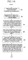
- the base station 14 periodically and continuously transmits the pilot code to all subscriber units 16 located within the operating range of the base station 14 (step 150).
- the base station 14 also continuously searches for a short code transmitted by the subscriber unit 16 (step 152).
- the subscriber unit 16 acquires the pilot code and synchronizes its transmit spreading code generator to the pilot code.
- the subscriber unit 16 also periodically checks to ensure it is synchronized. If synchronization is lost, the subscriber unit 16 reacquires the pilot signal transmitted by the base station (step 156).
- the subscriber unit 16 starts transmitting a short code at the minimum power level P 0 (step 158) and continuously increases the transmission power level while retransmitting the short code (step 160) until it receives an acknowledgment from the base station 14 that the short code has been detected by the base station 14.
- the access code in the preferred embodiment is approximately 30 million chips in length. However, the short code is much smaller.
- the short code can be chosen to be any length that is sufficiently short to permit quick detection. There is an advantage in choosing a short code length such that it divides the access code period evenly.
- the short code is preferably chosen to be 32, 64 or 128 chips in length. Alternatively, the short code may be as short as one symbol length, as will be described in detail hereinafter.
- the base station 14 Since the start of the short code and the start of the access code are synchronized, once the base station 14 acquires the short code, the base station 14 knows that the corresponding phase of the access code is an integer multiple of N chips from the phase of the short code where N is the length of the short code. Accordingly, the base station 14 does not have to search all possible phases corresponding to the maximum round trip propagation delay.
- the short code Using the short code, the correct phase for detection by the base station 14 occurs much more frequently.
- the short code is quickly detected (step 162) and the transmission power overshoot is limited.
- the transmission power ramp-up rate may be significantly increased without concern for a large power overshoot.
- the power ramp-up rate using the short code is 1 dB per millisecond.
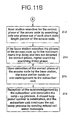
- the base station 14 subsequently transmits a short code detection indication signal (step 164) to the subscriber unit 16 which enters the second stage of the power ramp-up upon receiving this indication.
- the subscriber unit 16 ceases transmitting the short code (step 166) and starts continuously transmitting a periodic access code (step 166).
- the subscriber unit 16 continues to ramp-up its transmission power while transmitting the access code, however the ramp-up rate is now much lower than the previous ramp-up rate used with the short code (step 168).
- the ramp-up rate with the access code is preferably 0.05 dB per millisecond. The slow ramp-up avoids losing synchronization with the base station 14 due to small changes in channel propagation characteristics.
- the base station 14 has detected the short code at the proper phase and power level (step 162).
- the base station 14 must now synchronize to the access code which is the same length as all other spreading codes and much longer than the short code. Utilizing the short code, the base station 14 is able to detect the proper phase of the access code much more quickly.
- the base station 14 quickly acquires the access code of the proper phase and power level by: 1) detecting the short code; and 2) determining the proper phase of the access code by searching every N chips of the access code from the beginning of the short code.
- the base station 14 restarts the search for the access code by searching every chip instead of every N chips (step 172).
- the base station 14 transmits an access code detection acknowledgment (step 176) to the subscriber unit 16 which ceases the transmission power increase (step 178) upon receiving this acknowledgment.
- closed loop power control and call setup signaling is performed (step 180) to establish the two-way communication link.
- the subscriber unit 16 may ramp-up the transmission power level at a much higher rate by using a short code.
- the short code is quickly detected after the transmission power level surpasses the minimum detection level, thus minimizing the amount of transmission power overshoot.
- the short codes are dynamically selected and updated in accordance with the following procedure.
- the period of the short code is equal to one symbol length and the start of each period is aligned with a symbol boundary.
- the short codes are generated from a regular length spreading code. A symbol length portion from the beginning of the spreading code is stored and used as the short code for the next 3 milliseconds. Every 3 milliseconds, a new symbol length portion of the spreading code replaces the old short code. Since the spreading code period is an integer multiple of 3 milliseconds, the same short codes are repeated once every period of the spreading code. Periodic updating of the short code averages the interference created by the short code over the entire spectrum.
- the base station 14 comprises a receiver section 50, a transmitter section 52 and a diplexer 54.
- An RF receiver 56 receives and down-converts the RF signal received from the diplexer 54.
- the receive spreading code generator 58 outputs a spreading code to both the data receiver 60 and the code detector 62.
- the spreading code is correlated with the baseband signal to extract the data signal which is forwarded for further processing.
- the received baseband signal is also forwarded to the code detector 62 which detects the access code or the short code from the subscriber unit 16 and adjusts the timing of the spreading code generator 58 to establish a communication channel 18.
- the transmit spreading code generator 64 outputs a spreading code to the data transmitter 66 and the pilot code transmitter 68.
- the pilot code transmitter 68 continuously transmits the periodic pilot code.
- the data transmitter 66 transmits the short code detect indication and access code detect acknowledgment after the code detector 62 has detected the short code or the access code respectively.
- the data transmitter also sends other message and data signals.
- the signals from the data transmitter 66 and the pilot code transmitter 68 are combined and up-converted by the RF transmitter 70 for transmission to the subscriber units 16.
- the subscriber unit 16 comprises a receiver section 72, a transmitter section 74 and a diplexer 84.
- An RF receiver 76 receives and down-converts the RF signal received from the diplexer 84.
- a pilot code detector 80 correlates the spreading code with the baseband signal to acquire the pilot code transmitted by the base station 16. In this manner, the pilot code detector 80 maintains synchronization with the pilot code.
- the receiver spreading code generator 82 generates and outputs a spreading code to the data receiver 78 and the pilot code detector 80.
- the data receiver 78 correlates the spreading code with the baseband signal to process the short code detect indication and the access code detect acknowledgment transmitted by the base station 16.
- the transmitter section 74 comprises a spreading code generator 86 which generates and outputs spreading codes to a data transmitter 88 and a short code and access code transmitter 90.
- the short code and access code transmitter 90 transmits these codes at different stages of the power ramp-up procedure as hereinbefore described.
- the signals output by the data transmitter 88 and the short code and access code transmitter 90 are combined and up-converted by the RF transmitter 92 for transmission to the base station 14.
- the timing of the receiver spreading code generator 82 is adjusted by the pilot code-detector 80 through the acquisition process.
- the receiver and transmitter spreading code generators 82, 86 are also synchronized.
- the base station 14 transmits a pilot code while searching for the short code (step 200).
- the subscriber unit 16 acquires the pilot code transmitted from the base station 14 (step 202), starts transmitting a short code starting at a minimum power level P 0 which is guaranteed to be less than the required power, and quickly increases transmission power (step 204).
- the base station 14 acquires the correct phase of the short code, transmits an indication of this detection, and begins searching for the access code (step 208).
- the subscriber unit 16 Upon receiving the detection indication, the subscriber unit 16 ceases transmitting the short code and starts transmitting an access code.
- the subscriber unit 16 initiates a slow ramp-up of transmit power while sending the access code (step 210).
- the base station 14 searches for the correct phase of the access code by searching only one phase out of each short code length portion of the access code (step 212). If the base station 14 searches the phases of the access code up to the maximum round trip delay and has not detected the correct phase, the search is repeated by searching every phase (step 214).
- the base station 14 Upon detection of the correct phase of the access code by the base station 14, the base station 14 sends an acknowledgment to the subscriber unit 16 (step 216). Reception of the acknowledgment by the subscriber unit 16 concludes the ramp-up process.
- a closed loop power control is established, and the subscriber unit 16 continues the call setup process by sending related call setup messages (step 218).
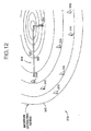
- the propagation of certain signals in the establishment of a communication channel 318 between a base station 314 and a plurality of subscriber units 316 is shown.
- the forward pilot signal 320 is transmitted from the base station 314 at time t0, and is received by a subscriber unit 316 after a propagation delay ⁇ t.
- the subscriber unit 316 transmits an access signal 322 which is received by the base station 314 after a further propagation delay of ⁇ t. Accordingly, the round trip propagation delay is 2 ⁇ t.
- the access signal 322 is transmitted epoch aligned to the forward pilot signal 320, which means that the code phase of the access signal 322 when transmitted is identical to the code phase of the received forward pilot signal 320.
- the round trip propagation delay depends upon the location of a subscriber unit 316 with respect to the base station 314. Communication signals transmitted between a subscriber unit 316 located closer to the base station 314 will experience a shorter propagation delay than a subscriber unit 316 located further from the base station 314. Since the base station 314 must be able to acquire subscriber units 316 located at any position within the cell 330, the base station 314 must search all code phases of the access signal corresponding to the entire range of propagation delays of the cell 330.
- a subscriber unit 316 desires the establishment of a channel 318 with a base station 314 with which it has never established a channel, the subscriber unit 316 has no knowledge of the two-way propagation delay. Accordingly, the subscriber unit 316 enters the initial acquisition channel establishment process.
- the subscriber unit 316 selects a low initial power level and zero code phase delay, (epoch aligning the code phase of the transmitted access signal 322 to the code phase of the received forward pilot signal 320), and commences transmitting the access signal 322 while slowly (0.05-0.1 dB/msec) ramping-up transmission power (step 400). While the subscriber unit 316 is awaiting receipt of the confirmation signal from the base station 314, it varies the code phase delay in predetermined steps from zero to the delay corresponding to the periphery of the cell 330, (the maximum code phase delay) , allowing sufficient time between steps for the base station 314 to detect the access signal 322 (step 402). If the subscriber unit 316 reaches the code phase delay corresponding to the periphery of the cell 330, it repeats the process of varying the code phase delay while continuing the slow power ramp-up (step 402).
- the base station 314 In order to acquire subscriber units 316 desiring access, the base station 314 continuously transmits a forward pilot signal 320 and attempts to detect the access signals 322 from subscriber units 316 (step 404). Rather than test for access signals 322 at all code phase delays within the cell 330 as with current systems, the base station 314 need only test code phase delays centered about the periphery of the cell 330.
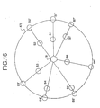
- the base station 314 detects the access signal 322 (step 406) when the subscriber unit 316 begins transmitting with sufficient power at the code phase delay which makes the subscriber unit 316 appear to be at the periphery of the cell 330, thereby "virtually" locating the subscriber unit 316 at the periphery of the cell 330.
- the base station 314 transmits a signal to the subscriber unit 316 which confirms that the access signal 322 has been received (step 408) and continues with the channel establishment process (step 410).
- the subscriber unit 316 receives the confirmation signal (step 412), it ceases the ramp-up of transmission power, ceases varying the code phase delay (step 414) and records the value of the code phase delay for subsequent re-acquisitions (step 416). The subscriber unit 316 then continues the channel establishment process including closed-loop power transmission control (step 418).
- a subscriber unit 316 desires the establishment of a channel 318 with a base station 314, the subscriber unit 316 enters the re-acquisition channel establishment process shown in Figure 14 .
- the subscriber unit 316 selects a low initial power level and the code phase delay recorded during the initial acquisition process, (shown in Figure 13 ), and commences continuously transmitting the access signal 322 while quickly (1 dB/msec) ramping-up transmission power (step 420). While the subscriber unit 316 is awaiting receipt of the confirmation signal from the base station 314, it slightly varies the code phase delay of the access signal 322 about the recorded code phase delay, allowing sufficient time for the base station 314 to detect the access signal 322 before changing the delay (step 422).
- the base station 314 transmits a forward pilot signal 320 and tests only the code phase delays at the periphery of the cell 330 in attempting to acquire the subscriber units 316 within its operating range (step 424).
- the base station 314 detects the access signal 322 when the subscriber unit 316 transmits with sufficient power at the code phase delay which makes the subscriber unit 316 appear to be at the periphery of the cell 330 (step 426).
- the base station 314 transmits a signal to the subscriber unit 316 which confirms that the access signal 322 has been received (step 428) and continues with the channel establishment process (step 430).
- the subscriber unit 316 When the subscriber unit 316 receives the confirmation signal (step 432) it ceases power ramp-up, ceases varying the code phase delay (step 434) and records the present value of the code phase delay for subsequent re-acquisitions (step 436). This code phase delay may be slightly different from the code phase delay initially used when starting the re-acquisitions process (step 422). The subscriber unit 316 then continues the channel establishment process at the present power level (step 438). If a subscriber unit 316 has not received a confirmation signal from the base station 314 after a predetermined time, the subscriber unit 316 reverts to the initial acquisition process described in Figure 13 .
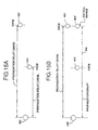
- a base station 460 communicates with two subscriber units 462, 464.
- the first subscriber unit 462 is located 30 km from the base station 460 at the maximum operating range.
- the second subscriber unit 464 is located 15 km from the base station 460.
- the propagation delay of Tx and Rx communications between the first subscriber unit 462 and the base station 460 will be twice that of communications between the second subscriber unit 464 and the base station 460.
- a subscriber unit 316 which has achieved a sufficient power level will be acquired by the base station 314 in approximately 2 msec. Due to the shorter acquisition time, the subscriber unit 316 can ramp-up at a much faster rate, (on the order of 1 dB/msec), without significantly overshooting the desired power level. Assuming the same 20 dB power back-off, it would take the subscriber unit 316 approximately 20 msec to reach the sufficient power level for detection by the base station 314. Accordingly, the entire duration of the re-acquisition process of the present invention is approximately 22 msec, which is an order of magnitude reduction from prior art reacquisition methods.
- a subscriber unit 500 made in accordance with this embodiment of the present invention is shown in Figure 17 .
- the subscriber unit 500 includes a receiver section 502 and a transmitter section 504.
- An antenna 506 receives a signal from the base station 314, which is filtered by a band-pass filter 508 having a bandwidth equal to twice the chip rate and a center frequency equal to the center frequency of the spread spectrum system's bandwidth.
- the output of the filter 508 is down-converted by a mixer 510 to a baseband signal using a constant frequency (Fc) local oscillator.
- the output of the mixer 510 is then spread spectrum decoded by applying a PN sequence to a mixer 512 within the PN Rx generator 514.
- the output of the mixer 512 is applied to a low pass filter 516 having a cutoff frequency at the data rate (Fb) of the PCM data sequence.
- the output of the filter 516 is input to a coder/decoder (codec) 518 which interfaces with the communicating entity 520.
- a baseband signal from the communicating entity 520 is pulse code modulated by the codec 518.
- a 32 kilobit per second adaptive pulse code modulation (ADPCM) is used.
- the PCM signal is applied to a mixer 522 within a PN Tx generator 524.
- the mixer 522 multiplies the PCM data signal with the PN sequence.
- the output of the mixer 522 is applied to low-pass filter 526 whose cutoff frequency is equal to the system chip rate.
- the output of the filter 526 is then applied to a mixer 528 and suitably up-converted, as determined by the carrier frequency Fc applied to the other terminal.
- the up-converted signal is then passed through a band-pass filter 530 and to a broadband RF amplifier 532 which drives an antenna 534.
- the microprocessor 536 controls the acquisition process as well as the Rx and Tx PN generators 514, 524.
- the microprocessor 536 controls the code phase delay added to the Rx and Tx PN generators 514, 524 to acquire the forward pilot signal 320, and for the subscriber unit 500 to be acquired by the base station 314, and records the code phase difference between these PN generators. For re-acquisition the microprocessor 536 adds the recorded delay to the Tx PN generator 524.
- the base station 314 uses a configuration similar to the subscriber unit 316 to detect PN coded signals from the subscriber unit 500.
- the microprocessor (not shown) in the base station 314 controls the Rx PN generator in a similar manner to make the code phase difference between Rx PN generator and the Tx PN generator equivalent to the two-way propagation delay of the subscriber unit's 316 virtual location.
- the subscriber unit 316 continuously transmits an epoch aligned access signal 322 to the base station 314 (step 600) when the establishment of a channel 318 is desired. While the subscriber unit 316 is awaiting the receipt of a confirmation signal from the base station 314, it'continuously increases the transmission power as it continues transmission of the access signal 322 (step 602).
- the base station 314 transmits a forward pilot signal 320 and sweeps the cell by searching all code phases corresponding to the entire range of propagation delays of the cell (step 604) and detects the epoch aligned access signal 322 sent from the subscriber unit 316 after the transmission has achieved sufficient power for detection (step 606).
- the base station 314 transmits a signal to the subscriber unit 316 (step 608) which confirms that the access signal 322 has been received.
- the subscriber unit 316 receives the confirmation signal (step 610) and ceases the increase in transmission power (step 612).
- the base station 314 determines the desired code phase delay of the subscriber unit 316 by noting the difference (step 614) between the Tx and Rx PN generators 524, 514 after acquiring the subscriber unit 316.
- the desired code phase delay value is sent to the subscriber unit 316 (step 616) as an OA&M message, which receives and stores the value (step 618) for use during re-acquisition, and continues with the channel establishment process (steps 622 and 624).
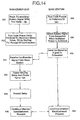
- FIG. 19 an alternative method of fast reacquisition in accordance with the present invention is shown.
- the subscriber unit 316 transmits the access signal 322 with the desired code phase delay as in the preferred embodiment.
- the base station 314 need only search the code phase delays centered about the periphery of' the cell to acquire the access signals 322 of such subscriber units 316 (step 630). Thus, a subscriber unit 316 may ramp-up power rapidly to exploit the more frequent acquisition opportunities.
- the subscriber unit 316 implements the delay the same way as in the preferred embodiment.
- the base station 314 subsequently detects the subscriber unit 316 at the periphery of the cell (step 636), sends a confirmation signal to the subscriber unit (step 637) and recalculates the desired code phase delay value, if necessary. Recalculation (step 638) compensates for propagation path changes, oscillator drift and other communication variables.
- the subscriber unit 316 receives the confirmation signal from the base station 316 (step 639).
- the base station 314 sends the updated desired code phase delay value to the subscriber unit 316 (step 640) which receives and stores the updated value (step 642).
- the subscriber unit 316 and the base station 314 then continue the channel establishment process communications (steps 644 and 646).
- the alternative embodiment requires the base station to search both the code phase delays centered on the periphery of the cell to re-acquire previously acquired subscriber units and the code phase delays for the entire cell to acquired subscriber units which have never been acquired.
- FIG. 20 the tasks associated with initial acquisition of a never-acquired subscriber unit 316 by a base station 314 in accordance with a second alternative embodiment of the present invention are shown.
- the access signal 320 remains epoch aligned to the forward pilot signal 320.
- the base station 314 and subscriber unit 316 change the code phase alignment of the access signal 322 from epoch aligned to delayed, (by the code phase delay), to make the subscriber unit 316 appear at the periphery of the cell. This change is performed at a designated time.
- Steps 700 through 718 are the same as the corresponding steps 600 through 618 shown in Figure 18 .
- the base station 314 sends the desired delay value to the subscriber unit 316 (step 716) the base station 314 sends a message to the subscriber unit 316 to switch to the desired delay value at a time referenced to a sub-epoch of the forward pilot signal 320 (step 720).
- the subscriber unit 316 receives this message (step 722), and both units 314, 316 wait until the switchover time is reached (steps 724, 730).
- the base station 314 adds the desired delay value to its Rx PN operator (step 732) and the subscriber unit 316 adds the same desired delay value to its Tx PN generator (step 726).
- the subscriber unit 316 and the base station 314 then continue the channel establishment process communication (step 728, 734).
Abstract
Description
- The present invention relates generally to CDMA communication systems. More specifically, the present invention relates to a CDMA communication system which utilizes the transmission of short codes from subscriber units to a base station to reduce the time required for the base station to detect the signal from a subscriber unit. The improved detection time allows a faster ramp-up of the initial transmit power from the subscriber units while reducing the unnecessary power overshoot.
- The use of wireless telecommunication systems has grown dramatically in the last decade as the reliability and capacity of the systems have improved. Wireless communication systems are being utilized in a variety of applications where land line based systems are impractical or impossible to use. Applications of wireless communications include cellular phone communications, communications in remote locations, and temporary communications for disaster recovery. Wireless communication systems have also become an economically viable alternative to replacing aging telephone lines and outdated' telephone equipment.
- The portion of the RF spectrum available for use by wireless communication systems is a critical resource. The RF spectrum must be shared among all commercial, governmental and military applications. There is a constant desire to improve the efficiency of wireless communication systems in order to increase system capacity.
- Code division multiple access (CDMA) wireless communication systems have shown particular promise in this area. Although more traditional time division multiple access (TDMA) and frequency division multiple access (FDMA) systems have improved using the latest technological advances, CDMA systems, in particular Broadband Code Division Multiple Access™ (B-CDMA™) systems, have significant advantages over TDMA and FDMA systems. This efficiency is due to the improved coding and modulation density, interference rejection and multipath tolerance of B-CDMA™ systems, as well as reuse of the same spectrum in every communication cell. The format of CDMA communication signals also makes it extremely difficult to intercept calls, thereby ensuring greater privacy for callers and providing greater immunity against fraud.
- In a CDMA system, the same portion of the frequency spectrum is used for communication by all subscriber units. Each subscriber unit's baseband data signal is multiplied by a code sequence, called the "spreading code", which has a much higher rate than the data. The ratio of the spreading code rate to the data symbol rate is called the "spreading factor" or the "processing gain". This coding results in a much wider transmission spectrum than the spectrum of the baseband data signal, hence the technique is called "spread spectrum". Subscriber units and their communications can be discriminated by assigning a unique spreading code to each communication link which is called a CDMA channel. Since all communications are sent over the same frequency band, each CDMA communication overlaps communications from other subscriber units and noise-related signals in both frequency and time.
- The use of the same frequency spectrum by a plurality of subscriber units increases the efficiency of the system. However, it also causes a gradual degradation of the performance of the system as the number of users increase. Each subscriber unit detects communication signals with its unique spreading code as valid signals and all other signals are viewed as noise. The stronger the signal from a subscriber unit arrives at the base station, the more interference the base station experiences when receiving and demodulating signals from other subscriber units. Ultimately, the power from one subscriber unit may be great enough to terminate communications of other subscriber units. Accordingly, it is extremely important in wireless CDMA communication systems to control the transmission power of all subscriber units. This is best accomplished by using a closed loop power control algorithm once a communication link is established.
- The control of transmission power is particularly critical when a subscriber unit is attempting to initiate communications with a base station and a power control loop has not yet been established. Typically, the transmission power required from a subscriber unit changes continuously as a function of the propagation loss, interference from other subscribers, channel noise, fading and other channel characteristics. Therefore, a subscriber unit does not know the power level at which it should start transmitting. If the subscriber unit begins transmitting at a power level that is too high, it may interfere with the communications of other subscriber units and may even terminate the communications of other subscriber units. If the initial transmission power level is too low, the subscriber unit will not be detected by the base station and a communication link will not be established.
- There are many methods for controlling transmission power in a CDMA communication system. For example,
U.S. Patent No. 5,056,109 (Gilhousen et al. ) discloses a transmission power control system wherein the transmission power of the subscriber unit is based upon periodic signal measurements from both the subscriber unit and the base station. The base station transmits a pilot signal to all subscriber units which analyze the received pilot signal, estimate the power loss in the transmitted signal and adjust their transmission power accordingly. Each subscriber unit includes a non-linear loss output filter which prevents sudden increases in power which would cause interference to other subscriber units. This method is too complex to permit a base station to quickly acquire a subscriber unit while limiting the interference to other subscriber units. In addition, the propagation losses, interference and noise levels experienced in a forward link (transmission from the base station to a subscriber unit) is often not the same as in a reverse link (transmission from a subscriber unit to the base station). Reverse link power estimates based on forward link losses are not precise. - Many other types of prior art transmission power control systems require complex control signaling between communicating units or preselected transmission values to control transmission power. These power control techniques are inflexible and often impractical to implement.
- Additionally,
EP 0 565 507 A2 discloses a system for minimizing interference between two radio stations at the initiation of radio communications. A mobile station initiates a low level access signal and incrementally increases the transmission power level until the base station detects the signal. Once detected, the power level of the message is maintained at the detected level so that the signal interference is avoided.EP 0 565 507 A2 also discloses a method for synchronizing random access communications between mobile stations and the base station despite the variations in the distance between them. - Accordingly, there is a need for an efficient method of controlling the initial ramp-up of transmission power by subscriber units in a wireless CDMA communication system.
- The present invention comprises a novel method of controlling transmission power during the establishment of a channel in a CDMA communication system by utilizing the transmission of a short code from a subscriber unit to a base station during initial power ramp-up. The short code is a sequence for detection by the base station which has a much shorter period than a conventional spreading code. The ramp-up starts from a power level that is guaranteed to be lower than the required power level for detection by the base station. The subscriber unit quickly increases transmission power while repeatedly transmitting the short code until the signal is detected by the base station. Once the base station detects the short code, it sends an indication to the subscriber unit to cease increasing transmission power. The use of short codes limits power overshoot and interference to other subscriber stations and permits the base station to quickly synchronize to the spreading code used by the subscriber unit.
- Accordingly, it is an object of the present invention to provide an improved technique for controlling power ramp-up during establishment of a communication channel between a CDMA subscriber unit and base station.
- Other objects and advantages of the present invention will become apparent after reading the description of a presently preferred embodiment.
-
-
Figure 1 is a schematic overview of a code division multiple access communication system in accordance with the present invention; -
Figure 2 is a diagram showing the operating range of a base station; -
Figure 3 is a timing diagram of communication signals between a base station and a subscriber unit; -
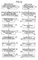
Figure 4 is a flow diagram of the establishment of a communication channel between a base station and a subscriber unit; -
Figure 5 is a graph of the transmission power output from a subscriber unit; -
Figures 6A and6B are flow diagrams of the establishment of a communication channel between a base station and a subscriber unit in accordance with the preferred embodiment of the present invention using short codes; -
Figure 7 is a graph of the transmission power output from a subscriber unit using short codes; -
Figure 8 shows the adaptive selection of short codes; -
Figure 9 is a block diagram of a base station in accordance with the present invention; -
Figure 10 is a block diagram of the subscriber unit in accordance with the present invention; -
Figures 11A and11B are flow diagrams of the ramp-up procedure implemented in accordance with the present invention; and -
Figure 12 is a diagram showing the propagation of signals between a base station and a plurality of subscriber units; -
Figure 13 is a flow diagram of the preferred embodiment of the initial establishment of a communication channel between a base station and a subscriber unit using slow initial acquisition; -
Figure 14 is a flow diagram of the preferred embodiment of the reestablishment of a communication channel between a base station and a subscriber unit using fast re-acquisition; -
Figure 15A is a diagram of the communications between a base station and a plurality of subscriber units; -
Figure 15B is a diagram of the base station and a subscriber unit which has been virtually located; -
Figure 16 is a schematic overview of a plurality of subscriber units which have been virtually located; -
Figure 17 is a subscriber unit made in accordance with the teachings of the present invention; -
Figure 18 is a flow diagram of an alternative embodiment of the initial establishment of a communication channel between a base station and a subscriber unit using slow initial acquisition; -
Figure 19 is a flow diagram of an alternative embodiment of the reestablishment of a communication channel between a base station and a subscriber unit using fast re-acquisition; and -
Figure 20 is a flow diagram of a second alternative embodiment of the initial establishment of a communication channel between a base station and a subscriber unit using slow initial acquisition. - The preferred embodiment will be described with reference to the drawing figures where identical numerals represent similar elements throughout.
- A
communication network 10 embodying the present invention is shown inFigure 1 . Thecommunication network 10 generally comprises one ormore base stations 14, each of which is in wireless communication with a plurality ofsubscriber units 16, which may be fixed or mobile. Eachsubscriber unit 16 communicates with either theclosest base station 14 or thebase station 14 which provides the strongest communication signal. Thebase stations 14 also communicate with abase station controller 20, which coordinates communications amongbase stations 14. Thecommunication network 10 may also be connected to a public switched telephone network (PSTN) 22, wherein thebase station controller 20 also coordinates communications between thebase stations 14 and thePSTN 22. Preferably, eachbase station 14 communicates with thebase station controller 20 over a wireless link, although a land line may also be provided. A land line is particularly applicable when abase station 14 is in close proximity to thebase station controller 20. - The
base station controller 20 performs several functions. Primarily, thebase station controller 20 provides all of the operations, administrative and maintenance (OA&M) signaling associated with establishing and maintaining all of the wireless communications between thesubscriber units 16, thebase stations 14, and thebase station controller 20. Thebase station controller 20 also provides an interface between thewireless communication system 10 and thePSTN 22. This interface includes multiplexing and demultiplexing of the communication signals that enter and leave thesystem 10 via thebase station controller 20. Although thewireless communication system 10 is shown employing antennas to transmit RF signals, one skilled in the art should recognize that communications may be accomplished via microwave or satellite uplinks. Additionally, the functions of thebase station controller 20 may be combined with abase station 14 to form a "master base station". - Referring to
Figure 2 , the propagation of signals between abase station 14 and a plurality ofsubscriber units 16 is shown. A two-way communication channel (link) 18 comprises a signal transmitted 20 (Tx) from thebase station 14 to thesubscriber unit 16 and a signal received 22 (Rx) by thebase station 14 from thesubscriber unit 16. TheTx signal 20 is transmitted from thebase station 14 and is received by thesubscriber unit 16 after a propagation delay Δt. Similarly, theRx 22 signal originates at thesubscriber unit 16 and terminates at thebase station 14 after a further propagation delay Δt. Accordingly, the round trip propagation delay is 2Δt. In the preferred embodiment, thebase station 14 has an operating range of approximately 30 kilometers. The roundtrip propagation delay 24 associated with asubscriber unit 16 at the maximum operating range is 200 microseconds. - It should be apparent to those of skill in the art that the establishment of a communication channel between a base station and a subscriber unit is a complex procedure involving many tasks performed by the
base station 14 and thesubscriber unit 16 which are outside the scope of the present invention. The present invention is directed to initial power ramp-up and synchronization during the establishment of a communication channel. - Referring to
Figure 3 , the signaling between abase station 14 and asubscriber unit 16 is shown. In accordance with the present invention, thebase station 14 continuously transmits apilot code 40 to all of thesubscriber units 16 located within the transmitting range of thebase station 14. Thepilot code 40 is a spreading code which carries no data bits. Thepilot code 40 is used forsubscriber unit 16 acquisition and synchronization, as well as for determining the parameters of the adaptive matched filter used in the receiver. - The
subscriber unit 16 must acquire thepilot code 40 transmitted by thebase station 14 before it can receive or transmit any data. Acquisition is the process whereby thesubscriber unit 16 aligns its locally generated spreading code with the receivedpilot code 40. Thesubscriber unit 16 searches through all of the possible phases of the receivedpilot code 40 until it detects the correct phase, (the beginning of the pilot code 40). - The
subscriber unit 16 then synchronizes its transmit spreading code to the receivedpilot code 40 by aligning the beginning of its transmit spreading code to the beginning of thepilot code 40. One implication of this receive and transmit synchronization is that thesubscriber unit 16 introduces no additional delay as far as the phase of the spreading codes are concerned. Accordingly, as shown inFigure 3 , the relative delay between thepilot code 40 transmitted from thebase station 14 and the subscriber unit's transmit spreadingcode 42 received at thebase station 14 is 2Δt, which is solely due to the round trip propagation delay. - In the preferred embodiment, the pilot code is 29,877,120 chips in length and takes approximately 2 to 5 seconds to transmit, depending on the spreading factor. The length of the
pilot code 40 was chosen to be a multiple of the data symbol no matter what kind of data rate or bandwidth is used. As is well known by those of skill in the art, alonger pilot code 40 has better randomness properties and the frequency response of thepilot code 40 is more uniform. Additionally, alonger pilot code 40 provides low channel cross correlation, thus increasing the capacity of thesystem 10 to supportmore subscriber units 16 with less interference. The use of along pilot code 40 also supports a greater number of random short codes. For synchronization purposes, thepilot code 40 is chosen to have the same period as all of the other spreading codes used by thesystem 10. Thus, once asubscriber unit 16 acquires thepilot code 40, it is synchronized to all other signals transmitted from thebase station 14. - During idle periods, when a call is not in progress or pending, the
subscriber unit 16 remains synchronized to thebase station 14 by periodically reacquiring thepilot code 40. This is necessary for thesubscriber unit 16 to receive and demodulate any downlink transmissions, in particular paging messages which indicate incoming calls. - When a communication link is desired, the
base station 14 must acquire the signal transmitted from thesubscriber unit 16 before it can demodulate the data. Thesubscriber unit 16 must transmit an uplink signal for acquisition by thebase station 14 to begin establishing the two-way communication link. A critical parameter in this procedure is the transmission power level of thesubscriber unit 16. A transmission power level that is too high can impair communications in the whole service area, whereas a transmission power level that is too low can prevent thebase station 14 from detecting the uplink signal. - In a first embodiment of the present invention the
subscriber unit 16 starts transmitting at a power level guaranteed to be lower than what is required and increases transmission power output until the correct power level is achieved. This avoids sudden introduction of a strong interference, hence improvingsystem 10 capacity. - The establishment of a communication channel in accordance with the present invention and the tasks performed by the
base station 14 and asubscriber unit 16 are shown inFigure 4 . Althoughmany subscriber units 16 may be located within the operating range of thebase station 14, reference will be made hereinafter to asingle subscriber unit 16 for simplicity in explaining the operation of the present invention. - The
base station 14 begins by continuously transmitting aperiodic pilot code 40 to allsubscriber units 16 located within the operating range of the base station 14 (step 100). As thebase station 14 transmits the pilot code 40 (step 100), thebase station 14 searches (step 101) for an "access code" 42 transmitted by asubscriber unit 16. Theaccess code 42 is a known spreading code transmitted from asubscriber unit 16 to thebase station 14 during initiation of communications and power ramp-up. Thebase station 14 must search through all possible phases (time shifts) of theaccess code 42 transmitted from thesubscriber unit 16 in order to find the correct phase. This is called the "acquisition" or the "detection" process (step 101). The longer theaccess code 42, the longer it takes for thebase station 14 to search through the phases and acquire the correct phase. - As previously explained, the relative delay between signals transmitted from the
base station 14 and return signals received at thebase station 14 corresponds to the round trip propagation delay 2Δt. The maximum delay occurs at the maximum operating range of thebase station 14, known as the cell boundary. Accordingly, thebase station 14 must search up to as many code phases as there are in the maximum round trip propagation delay, which is typically less code phases than there are in a code period. - For a data rate Rb and spreading code rate Rc, the ratio L = Rc/Rb is called the spreading factor or the processing gain. In the preferred embodiment of the present invention, the cell boundary radius is 30 km, which corresponds to approximately between 1000 and 2500 code phases in the maximum round trip delay, depending on the processing gain.
- If the
base station 14 has not detected the access code after searching through the code phases corresponding to the maximum round trip delay the search is repeated starting from the phase of thepilot code 40 which corresponds to zero delay (step 102). - During idle periods, the
pilot code 40 from thebase station 14 is received at thesubscriber unit 16 which periodically synchronizes its transmit spreading code generator thereto (step 103). If synchronization with thepilot code 40 is lost, thesubscriber unit 16 reacquires thepilot code 40 and resynchronizes (step 104). - When it is desired to initiate a communication link, the
subscriber unit 16 starts transmitting theaccess code 42 back to the base station 14 (step 106). Thesubscriber unit 16 continuously increases the transmission power while retransmitting the access code 42 (step 108) until it receives an acknowledgment from thebase station 14. Thebase station 14 detects theaccess code 42 at the correct phase once the minimum power level for reception has been achieved (step 110). Thebase station 14 subsequently transmits an access code detection acknowledgment signal (step 112) to thesubscriber unit 16. Upon receiving the acknowledgment, the subscriber unit ceases the transmission power increase (step 114). With the power ramp-up completed, closed loop power control and call setup signaling is performed (step 116) to establish the two-way communication link. - Although this embodiment limits
subscriber unit 16 transmission power, acquisition of thesubscriber unit 16 by thebase station 14 in this manner may lead to unnecessary power overshoot from thesubscriber unit 16, thereby reducing the performance of thesystem 10. - The transmission power output profile of the
subscriber unit 16 is shown inFigure 5 . At to, thesubscriber unit 16 starts transmitting at the starting transmission power level P0, which is a power level guaranteed to be less than the power level required for detection by thebase station 14. Thesubscriber unit 16 continually increases the transmission power level until it receives the detection indication from thebase station 14. For thebase station 14 to properly detect theaccess code 42 from thesubscriber unit 16 theaccess code 42 must: 1) be received at a sufficient power level; and 2) be detected at the proper phase. Accordingly, referring toFigure 5 , although theaccess code 42 is at a sufficient power level for detection by thebase station 14 at tp, thebase station 14 must continue searching for the correct phase of theaccess code 42 which occurs at tA. - Since the
subscriber unit 16 continues to increase the output transmission power level until it receives the detection indication from thebase station 14, the transmission power of theaccess code 42 exceeds the power level required for detection by thebase station 14. This causes unnecessary interference to allother subscriber units 16. If the power overshoot is too large, the interference toother subscriber units 16 may be so severe as to terminate ongoing communications ofother subscriber units 16. - The rate that the
subscriber unit 16 increases transmission power to avoid overshoot may be reduced, however, this results in a longer call setup time. Those of skill in the art would appreciate that adaptive ramp-up rates can also be used, yet these rates have shortcomings and will not appreciably eliminate power overshoot in all situations. - The preferred embodiment of the present invention utilizes "short codes" and a two-stage communication link establishment procedure to achieve fast power ramp-up without large power overshoots. The spreading code transmitted by the
subscriber unit 16 is much shorter than the rest of the spreading codes (hence the term short code), so that the number of phases is limited and thebase station 14 can quickly search through the code. The short code used for this purpose carries no data. - The tasks performed by the
base station 14 and thesubscriber unit 16 to establish a.communication channel using short codes in accordance with the preferred embodiment of the present invention are shown inFigures 6A and6B . During idle periods, thebase station 14 periodically and continuously transmits the pilot code to allsubscriber units 16 located within the operating range of the base station 14 (step 150). Thebase station 14 also continuously searches for a short code transmitted by the subscriber unit 16 (step 152). Thesubscriber unit 16 acquires the pilot code and synchronizes its transmit spreading code generator to the pilot code. Thesubscriber unit 16 also periodically checks to ensure it is synchronized. If synchronization is lost, thesubscriber unit 16 reacquires the pilot signal transmitted by the base station (step 156). - When a communication link is desired, the
subscriber unit 16 starts transmitting a short code at the minimum power level P0 (step 158) and continuously increases the transmission power level while retransmitting the short code (step 160) until it receives an acknowledgment from thebase station 14 that the short code has been detected by thebase station 14. - The access code in the preferred embodiment, as previously described herein, is approximately 30 million chips in length. However, the short code is much smaller. The short code can be chosen to be any length that is sufficiently short to permit quick detection. There is an advantage in choosing a short code length such that it divides the access code period evenly. For the access code described herein, the short code is preferably chosen to be 32, 64 or 128 chips in length. Alternatively, the short code may be as short as one symbol length, as will be described in detail hereinafter.
- Since the start of the short code and the start of the access code are synchronized, once the
base station 14 acquires the short code, thebase station 14 knows that the corresponding phase of the access code is an integer multiple of N chips from the phase of the short code where N is the length of the short code. Accordingly, thebase station 14 does not have to search all possible phases corresponding to the maximum round trip propagation delay. - Using the short code, the correct phase for detection by the
base station 14 occurs much more frequently. When the minimum power level for reception has been achieved, the short code is quickly detected (step 162) and the transmission power overshoot is limited. The transmission power ramp-up rate may be significantly increased without concern for a large power overshoot. In the preferred embodiment of the present invention, the power ramp-up rate using the short code is 1 dB per millisecond. - The
base station 14 subsequently transmits a short code detection indication signal (step 164) to thesubscriber unit 16 which enters the second stage of the power ramp-up upon receiving this indication. In this stage, thesubscriber unit 16 ceases transmitting the short code (step 166) and starts continuously transmitting a periodic access code (step 166). Thesubscriber unit 16 continues to ramp-up its transmission power while transmitting the access code, however the ramp-up rate is now much lower than the previous ramp-up rate used with the short code (step 168). The ramp-up rate with the access code is preferably 0.05 dB per millisecond. The slow ramp-up avoids losing synchronization with thebase station 14 due to small changes in channel propagation characteristics. - At this point, the
base station 14 has detected the short code at the proper phase and power level (step 162). Thebase station 14 must now synchronize to the access code which is the same length as all other spreading codes and much longer than the short code. Utilizing the short code, thebase station 14 is able to detect the proper phase of the access code much more quickly. Thebase station 14 begins searching for the proper phase of the access code (step 170). However, since the start of the access code is synchronized with the start of the short code, thebase station 14 is only required to search every N chips; where N = the length of the short code. In summary, thebase station 14 quickly acquires the access code of the proper phase and power level by: 1) detecting the short code; and 2) determining the proper phase of the access code by searching every N chips of the access code from the beginning of the short code. - If the proper phase of the access code has not been detected after searching the number of phases in the maximum round trip delay the
base station 14 restarts the search for the access code by searching every chip instead of every N chips (step 172). When the proper phase of the access code has been detected (step 174) thebase station 14 transmits an access code detection acknowledgment (step 176) to thesubscriber unit 16 which ceases the transmission power increase (step 178) upon receiving this acknowledgment. With the power ramp-up completed, closed loop power control and call setup signaling is performed (step 180) to establish the two-way communication link. - Referring to
Figure 7 , although the starting power level P0 is the same as in the prior embodiment, thesubscriber unit 16 may ramp-up the transmission power level at a much higher rate by using a short code. The short code is quickly detected after the transmission power level surpasses the minimum detection level, thus minimizing the amount of transmission power overshoot. - Although the same short code may be reused by the
subscriber unit 16, in the preferred embodiment of the present invention the short codes are dynamically selected and updated in accordance with the following procedure. Referring toFigure 8 , the period of the short code is equal to one symbol length and the start of each period is aligned with a symbol boundary. The short codes are generated from a regular length spreading code. A symbol length portion from the beginning of the spreading code is stored and used as the short code for the next 3 milliseconds. Every 3 milliseconds, a new symbol length portion of the spreading code replaces the old short code. Since the spreading code period is an integer multiple of 3 milliseconds, the same short codes are repeated once every period of the spreading code. Periodic updating of the short code averages the interference created by the short code over the entire spectrum. - A block diagram of the
base station 14 is shown inFigure 9 . Briefly described, thebase station 14 comprises areceiver section 50, atransmitter section 52 and adiplexer 54. AnRF receiver 56 receives and down-converts the RF signal received from thediplexer 54. The receive spreadingcode generator 58 outputs a spreading code to both thedata receiver 60 and thecode detector 62. In thedata receiver 60, the spreading code is correlated with the baseband signal to extract the data signal which is forwarded for further processing. The received baseband signal is also forwarded to thecode detector 62 which detects the access code or the short code from thesubscriber unit 16 and adjusts the timing of the spreadingcode generator 58 to establish acommunication channel 18. - In the
transmitter section 52 of thebase station 14, the transmit spreadingcode generator 64 outputs a spreading code to thedata transmitter 66 and thepilot code transmitter 68. Thepilot code transmitter 68 continuously transmits the periodic pilot code. Thedata transmitter 66 transmits the short code detect indication and access code detect acknowledgment after thecode detector 62 has detected the short code or the access code respectively. The data transmitter also sends other message and data signals. The signals from thedata transmitter 66 and thepilot code transmitter 68 are combined and up-converted by theRF transmitter 70 for transmission to thesubscriber units 16. - A block diagram of the
subscriber unit 16 is shown inFigure 10 . Briefly described, thesubscriber unit 16 comprises areceiver section 72, atransmitter section 74 and adiplexer 84. AnRF receiver 76 receives and down-converts the RF signal received from thediplexer 84. Apilot code detector 80 correlates the spreading code with the baseband signal to acquire the pilot code transmitted by thebase station 16. In this manner, thepilot code detector 80 maintains synchronization with the pilot code. The receiver spreadingcode generator 82 generates and outputs a spreading code to thedata receiver 78 and thepilot code detector 80. Thedata receiver 78 correlates the spreading code with the baseband signal to process the short code detect indication and the access code detect acknowledgment transmitted by thebase station 16. - The
transmitter section 74 comprises a spreadingcode generator 86 which generates and outputs spreading codes to adata transmitter 88 and a short code andaccess code transmitter 90. The short code andaccess code transmitter 90 transmits these codes at different stages of the power ramp-up procedure as hereinbefore described. The signals output by thedata transmitter 88 and the short code andaccess code transmitter 90 are combined and up-converted by theRF transmitter 92 for transmission to thebase station 14. The timing of the receiver spreadingcode generator 82 is adjusted by the pilot code-detector 80 through the acquisition process. The receiver and transmitter spreadingcode generators - An overview of the ramp-up procedure in accordance with the preferred current invention is summarized in
Figures 11A and11B . Thebase station 14 transmits a pilot code while searching for the short code (step 200). Thesubscriber unit 16 acquires the pilot code transmitted from the base station 14 (step 202), starts transmitting a short code starting at a minimum power level P0 which is guaranteed to be less than the required power, and quickly increases transmission power (step 204). Once the received power level at thebase station 14 reaches the minimum level needed for detection of the short code (step 206) thebase station 14 acquires the correct phase of the short code, transmits an indication of this detection, and begins searching for the access code (step 208). Upon receiving the detection indication, thesubscriber unit 16 ceases transmitting the short code and starts transmitting an access code. Thesubscriber unit 16 initiates a slow ramp-up of transmit power while sending the access code (step 210). Thebase station 14 searches for the correct phase of the access code by searching only one phase out of each short code length portion of the access code (step 212). If thebase station 14 searches the phases of the access code up to the maximum round trip delay and has not detected the correct phase, the search is repeated by searching every phase (step 214). Upon detection of the correct phase of the access code by thebase station 14, thebase station 14 sends an acknowledgment to the subscriber unit 16 (step 216). Reception of the acknowledgment by thesubscriber unit 16 concludes the ramp-up process. A closed loop power control is established, and thesubscriber unit 16 continues the call setup process by sending related call setup messages (step 218). - An alternative embodiment of the present invention in the reestablishment of a communication link will be described with reference to
Figure 12 . The propagation of certain signals in the establishment of acommunication channel 318 between abase station 314 and a plurality ofsubscriber units 316 is shown. Theforward pilot signal 320 is transmitted from thebase station 314 at time t0, and is received by asubscriber unit 316 after a propagation delay Δt. To be acquired by thebase station 314 thesubscriber unit 316 transmits anaccess signal 322 which is received by thebase station 314 after a further propagation delay of Δt. Accordingly, the round trip propagation delay is 2Δt. Theaccess signal 322 is transmitted epoch aligned to theforward pilot signal 320, which means that the code phase of theaccess signal 322 when transmitted is identical to the code phase of the receivedforward pilot signal 320. - The round trip propagation delay depends upon the location of a
subscriber unit 316 with respect to thebase station 314. Communication signals transmitted between asubscriber unit 316 located closer to thebase station 314 will experience a shorter propagation delay than asubscriber unit 316 located further from thebase station 314. Since thebase station 314 must be able to acquiresubscriber units 316 located at any position within thecell 330, thebase station 314 must search all code phases of the access signal corresponding to the entire range of propagation delays of thecell 330. - Referring to
Figure 13 , the tasks associated with initial acquisition of asubscriber unit 316 by abase station 314 are shown. When asubscriber unit 316 desires the establishment of achannel 318 with abase station 314 with which it has never established a channel, thesubscriber unit 316 has no knowledge of the two-way propagation delay. Accordingly, thesubscriber unit 316 enters the initial acquisition channel establishment process. - The
subscriber unit 316 selects a low initial power level and zero code phase delay, (epoch aligning the code phase of the transmittedaccess signal 322 to the code phase of the received forward pilot signal 320), and commences transmitting theaccess signal 322 while slowly (0.05-0.1 dB/msec) ramping-up transmission power (step 400). While thesubscriber unit 316 is awaiting receipt of the confirmation signal from thebase station 314, it varies the code phase delay in predetermined steps from zero to the delay corresponding to the periphery of thecell 330, (the maximum code phase delay) , allowing sufficient time between steps for thebase station 314 to detect the access signal 322 (step 402). If thesubscriber unit 316 reaches the code phase delay corresponding to the periphery of thecell 330, it repeats the process of varying the code phase delay while continuing the slow power ramp-up (step 402). - In order to acquire
subscriber units 316 desiring access, thebase station 314 continuously transmits aforward pilot signal 320 and attempts to detect the access signals 322 from subscriber units 316 (step 404). Rather than test foraccess signals 322 at all code phase delays within thecell 330 as with current systems, thebase station 314 need only test code phase delays centered about the periphery of thecell 330. - The
base station 314 detects the access signal 322 (step 406) when thesubscriber unit 316 begins transmitting with sufficient power at the code phase delay which makes thesubscriber unit 316 appear to be at the periphery of thecell 330, thereby "virtually" locating thesubscriber unit 316 at the periphery of thecell 330. Thebase station 314 then transmits a signal to thesubscriber unit 316 which confirms that theaccess signal 322 has been received (step 408) and continues with the channel establishment process (step 410). - Once the
subscriber unit 316 receives the confirmation signal (step 412), it ceases the ramp-up of transmission power, ceases varying the code phase delay (step 414) and records the value of the code phase delay for subsequent re-acquisitions (step 416). Thesubscriber unit 316 then continues the channel establishment process including closed-loop power transmission control (step 418). - On subsequent re-acquisitions when a
subscriber unit 316 desires the establishment of achannel 318 with abase station 314, thesubscriber unit 316 enters the re-acquisition channel establishment process shown inFigure 14 . Thesubscriber unit 316 selects a low initial power level and the code phase delay recorded during the initial acquisition process, (shown inFigure 13 ), and commences continuously transmitting theaccess signal 322 while quickly (1 dB/msec) ramping-up transmission power (step 420). While thesubscriber unit 316 is awaiting receipt of the confirmation signal from thebase station 314, it slightly varies the code phase delay of theaccess signal 322 about the recorded code phase delay, allowing sufficient time for thebase station 314 to detect theaccess signal 322 before changing the delay (step 422). Thebase station 314 as inFigure 13 , transmits aforward pilot signal 320 and tests only the code phase delays at the periphery of thecell 330 in attempting to acquire thesubscriber units 316 within its operating range (step 424). Thebase station 314 detects theaccess signal 322 when thesubscriber unit 316 transmits with sufficient power at the code phase delay which makes thesubscriber unit 316 appear to be at the periphery of the cell 330 (step 426). Thebase station 314 transmits a signal to thesubscriber unit 316 which confirms that theaccess signal 322 has been received (step 428) and continues with the channel establishment process (step 430). - When the
subscriber unit 316 receives the confirmation signal (step 432) it ceases power ramp-up, ceases varying the code phase delay (step 434) and records the present value of the code phase delay for subsequent re-acquisitions (step 436). This code phase delay may be slightly different from the code phase delay initially used when starting the re-acquisitions process (step 422). Thesubscriber unit 316 then continues the channel establishment process at the present power level (step 438). If asubscriber unit 316 has not received a confirmation signal from thebase station 314 after a predetermined time, thesubscriber unit 316 reverts to the initial acquisition process described inFigure 13 . - The effect of introducing a code phase delay in the
Tx 320 andRx 322 communications between thebase station 314 and asubscriber unit 316 will be explained with reference toFigures 15A and 15B . Referring toFigure 15A , abase station 460 communicates with twosubscriber units first subscriber unit 462 is located 30 km from thebase station 460 at the maximum operating range. Thesecond subscriber unit 464 is located 15 km from thebase station 460. The propagation delay of Tx and Rx communications between thefirst subscriber unit 462 and thebase station 460 will be twice that of communications between thesecond subscriber unit 464 and thebase station 460. - Referring to
Figure 15B , after an addeddelay value 466 is introduced into the Tx PN generator of thesecond subscriber unit 464 the propagation delay of communications between thefirst subscriber unit 462 and thebase station 460 will be the same as the propagation delay of communications between thesecond subscriber unit 464 and thebase station 460. Viewed from thebase station 460, it appears as though thesecond subscriber unit 464 is located at the virtual range 464'. - Referring to
Figure 16 , it can be seen that when a plurality of subscriber units S1 - S7 are virtually relocated S1' - S7' to thevirtual range 475, the base station B must only test the code phase delays centered about thevirtual range 475. - Utilizing the present invention, a
subscriber unit 316 which has achieved a sufficient power level will be acquired by thebase station 314 in approximately 2 msec. Due to the shorter acquisition time, thesubscriber unit 316 can ramp-up at a much faster rate, (on the order of 1 dB/msec), without significantly overshooting the desired power level. Assuming the same 20 dB power back-off, it would take thesubscriber unit 316 approximately 20 msec to reach the sufficient power level for detection by thebase station 314. Accordingly, the entire duration of the re-acquisition process of the present invention is approximately 22 msec, which is an order of magnitude reduction from prior art reacquisition methods. - A
subscriber unit 500 made in accordance with this embodiment of the present invention is shown inFigure 17 . Thesubscriber unit 500 includes areceiver section 502 and atransmitter section 504. Anantenna 506 receives a signal from thebase station 314, which is filtered by a band-pass filter 508 having a bandwidth equal to twice the chip rate and a center frequency equal to the center frequency of the spread spectrum system's bandwidth. The output of thefilter 508 is down-converted by amixer 510 to a baseband signal using a constant frequency (Fc) local oscillator. The output of themixer 510 is then spread spectrum decoded by applying a PN sequence to amixer 512 within thePN Rx generator 514. The output of themixer 512 is applied to alow pass filter 516 having a cutoff frequency at the data rate (Fb) of the PCM data sequence. The output of thefilter 516 is input to a coder/decoder (codec) 518 which interfaces with the communicatingentity 520. - A baseband signal from the communicating
entity 520 is pulse code modulated by thecodec 518. Preferably, a 32 kilobit per second adaptive pulse code modulation (ADPCM) is used. The PCM signal is applied to amixer 522 within aPN Tx generator 524. Themixer 522 multiplies the PCM data signal with the PN sequence. The output of themixer 522 is applied to low-pass filter 526 whose cutoff frequency is equal to the system chip rate. The output of thefilter 526 is then applied to amixer 528 and suitably up-converted, as determined by the carrier frequency Fc applied to the other terminal. The up-converted signal is then passed through a band-pass filter 530 and to abroadband RF amplifier 532 which drives anantenna 534. - The
microprocessor 536 controls the acquisition process as well as the Rx andTx PN generators microprocessor 536 controls the code phase delay added to the Rx andTx PN generators forward pilot signal 320, and for thesubscriber unit 500 to be acquired by thebase station 314, and records the code phase difference between these PN generators. For re-acquisition themicroprocessor 536 adds the recorded delay to theTx PN generator 524. - The
base station 314 uses a configuration similar to thesubscriber unit 316 to detect PN coded signals from thesubscriber unit 500. The microprocessor (not shown) in thebase station 314 controls the Rx PN generator in a similar manner to make the code phase difference between Rx PN generator and the Tx PN generator equivalent to the two-way propagation delay of the subscriber unit's 316 virtual location. Once thebase station 314 acquires the access signal 322 from thesubscriber unit 316, all other signals from thesubscriber unit 316 to the base station 314 (traffic, pilot, etc.) use the same code phase delay determined during the acquisition process. - It should be noted that although the invention has been described herein as the virtual locating of
subscriber units 316 at the periphery of thecell 330 the virtual location can be at any fixed distance from thebase station 314. - Referring to
Figure 18 , the tasks associated with initial acquisition of a "never-acquired"subscriber unit 316 by abase station 314 in accordance with an alternative embodiment of the present invention are shown. Thesubscriber unit 316 continuously transmits an epoch aligned access signal 322 to the base station 314 (step 600) when the establishment of achannel 318 is desired. While thesubscriber unit 316 is awaiting the receipt of a confirmation signal from thebase station 314, it'continuously increases the transmission power as it continues transmission of the access signal 322 (step 602). - To detect subscriber units which have never been acquired, the
base station 314 transmits aforward pilot signal 320 and sweeps the cell by searching all code phases corresponding to the entire range of propagation delays of the cell (step 604) and detects the epoch aligned access signal 322 sent from thesubscriber unit 316 after the transmission has achieved sufficient power for detection (step 606). Thebase station 314 transmits a signal to the subscriber unit 316 (step 608) which confirms that theaccess signal 322 has been received. Thesubscriber unit 316 receives the confirmation signal (step 610) and ceases the increase in transmission power (step 612). - The
base station 314 determines the desired code phase delay of thesubscriber unit 316 by noting the difference (step 614) between the Tx andRx PN generators subscriber unit 316. The desired code phase delay value is sent to the subscriber unit 316 (step 616) as an OA&M message, which receives and stores the value (step 618) for use during re-acquisition, and continues with the channel establishment process (steps 622 and 624). - Referring to
Figure 19 , an alternative method of fast reacquisition in accordance with the present invention is shown. When a communication channel must be reestablished between thesubscriber unit 316 and thebase station 314, thesubscriber unit 316 transmits theaccess signal 322 with the desired code phase delay as in the preferred embodiment. - With all of the previously acquired
subscriber units 316 at the same virtual range, thebase station 314 need only search the code phase delays centered about the periphery of' the cell to acquire the access signals 322 of such subscriber units 316 (step 630). Thus, asubscriber unit 316 may ramp-up power rapidly to exploit the more frequent acquisition opportunities. Thesubscriber unit 316 implements the delay the same way as in the preferred embodiment. Thebase station 314 subsequently detects thesubscriber unit 316 at the periphery of the cell (step 636), sends a confirmation signal to the subscriber unit (step 637) and recalculates the desired code phase delay value, if necessary. Recalculation (step 638) compensates for propagation path changes, oscillator drift and other communication variables. Thesubscriber unit 316 receives the confirmation signal from the base station 316 (step 639). - The
base station 314 sends the updated desired code phase delay value to the subscriber unit 316 (step 640) which receives and stores the updated value (step 642). Thesubscriber unit 316 and thebase station 314 then continue the channel establishment process communications (steps 644 and 646). - Note that the alternative embodiment requires the base station to search both the code phase delays centered on the periphery of the cell to re-acquire previously acquired subscriber units and the code phase delays for the entire cell to acquired subscriber units which have never been acquired.
- Referring to
Figure 20 , the tasks associated with initial acquisition of a never-acquiredsubscriber unit 316 by abase station 314 in accordance with a second alternative embodiment of the present invention are shown. In the embodiment shown inFigure 18 , when a never-acquiredsubscriber unit 316 is acquired, theaccess signal 320 remains epoch aligned to theforward pilot signal 320. In this embodiment, thebase station 314 andsubscriber unit 316 change the code phase alignment of the access signal 322 from epoch aligned to delayed, (by the code phase delay), to make thesubscriber unit 316 appear at the periphery of the cell. This change is performed at a designated time. - Steps 700 through 718 are the same as the
corresponding steps 600 through 618 shown inFigure 18 . However, after thebase station 314 sends the desired delay value to the subscriber unit 316 (step 716) thebase station 314 sends a message to thesubscriber unit 316 to switch to the desired delay value at a time referenced to a sub-epoch of the forward pilot signal 320 (step 720). Thesubscriber unit 316 receives this message (step 722), and bothunits steps 724, 730). At that time, thebase station 314 adds the desired delay value to its Rx PN operator (step 732) and thesubscriber unit 316 adds the same desired delay value to its Tx PN generator (step 726). Thesubscriber unit 316 and thebase station 314 then continue the channel establishment process communication (step 728, 734). - Although the invention has been described in part by making detailed reference to the preferred embodiment, such detail is intended to be instructive rather than restrictive. It will be appreciated by those skilled in the art that many variations may be made in the structure and mode of operation without departing from the spirit and scope of the invention as disclosed in the teachings herein.
-
- 1. A subscriber unit operable to perform an access procedure for establishing communications between the subscriber unit and a base station, the subscriber unit comprising:
- a transmitter configured to repeatedly transmit codes of a first type wherein each transmission of a code of the first type is transmitted at an increased power level with respect to a prior transmission of a code of the first type;
- a receiver configured to receive an acknowledgement from the base station wherein the acknowledgement signal is an indication to the subscriber unit that the base station has received a code of the first type;
- the transmitter further configured to transmit a code of a second type to said base station upon receipt by the receiver of said acknowledgement, and
- wherein the code of a second type includes access message data.
- 2. The subscriber unit of
aspect 1 wherein the transmitter is configured such that the code of the first type and the code of the second type are derived from a same code sequence. - 3. The subscriber unit of
aspect 1 wherein the code of the first type has a shorter bit length than the code of the second type. - 4. The subscriber unit of
aspect 2 wherein the same code sequence includes a spreading code. - 5. A subscriber unit operable to perform an access procedure for establishing communications, the subscriber unit comprising:
- a transmitter configured to receive a code of a first type and to transmit the received code of the first type, wherein the transmitted code of the first type does not include data of the subscriber unit;
- a receiver configured to receive an acknowledgement signal, the acknowledgement signal being an indication to the subscriber unit that a code of the first type was received;
- the transmitter further configured to repeatedly receive a code of the first type and to transmit each received code of the first type until the receiver receives the acknowledgement signal; wherein the received transmitted codes of a first type are transmitted at increasing power levels until the receiver has received the acknowledgement signal; and
- the transmitter, in response to the receiver receiving an acknowledgement, further configured to receive a code of a second type and to transmit the code of the second type.
- 6. The subscriber unit of
aspect 5 wherein the transmitter is configured such that said codes of a first type are dynamically selected codes associated with said code of a second type. - 7. The subscriber unit of
aspect 5 wherein each of the received transmitted codes of a first type is shorter than said code of a second type. - 8. The subscriber unit of
aspect 5 wherein said received transmitted codes of a first type carry no data.
Claims (30)
- A subscriber unit for performing an access procedure, the subscriber unit characterized by:means for transmitting wireless signals of a first type;means for receiving an indication that at least one of the wireless signals of the first type was detected; andmeans for transmitting a wireless signal of a second type.
- A subscriber unit according to claim 1 wherein the wireless signals of the first type are transmitted successively.
- A subscriber unit according to claim 2 wherein a beginning of each one of the successively transmitted transmissions, other than a first one of the successively transmitted transmissions, is at a higher power level with respect to a beginning of a prior one of the successively transmitted transmissions.
- A subscriber unit according to claim 2 wherein each one of the successively transmitted transmissions, other than a first one of the successively transmitted transmissions, is at a power level that is higher than the power level of a prior one of the successively transmitted transmissions.
- A subscriber unit according to claim 2 wherein the transmissions are successively sent until receipt of the indication.
- A subscriber unit according to claim 1 wherein the means for transmitting the wireless signals of the first type is configured to transmit the wireless signals of the first type when the subscriber unit is first accessing a network and wherein the wireless signals of the first type are used to convey information to facilitate establishment of a communication channel.
- A subscriber unit according to claim 1 wherein each transmitted wireless signal of the first type is produced using a sequence of chips, wherein the sequence of chips is not used to increase bandwidth.
- A subscriber unit according to claim 1 wherein at least two of the transmitted wireless signals of the first type are produced using different sequences of chips.
- A subscriber unit according to claim 1 wherein the wireless signal of the second type is a message that indicates that the subscriber unit wants to establish communications with a network.
- A subscriber unit according to claim 1 wherein each transmitted wireless signal of the first type and the wireless signal of the second type are produced using portions of a same sequence of chips, wherein the same sequence of chips is not used to increase bandwidth.
- A subscriber unit according to claim 1 wherein the wireless signal of the second type is transmitted only subsequent to the subscriber unit receiving the indication.
- A subscriber unit according to claim 1 wherein the wireless signals of the first type and the wireless signal of the second type are not closed loop power controlled.
- A subscriber unit according to claim 1 wherein the wireless signal of the second type is produced using an access code and data.
- A subscriber unit according to claim 1 wherein a communication channel is indicated to the subscriber unit in response to the wireless signal of the second type, wherein the communication channel is closed loop power controlled.
- A subscriber unit according to claim 1 wherein the transmitted wireless signals of the first type facilitate power control when the subscriber unit is first accessing a network.
- A subscriber unit according to claim 1 wherein each wireless signal of the first type is dynamically selected.
- A subscriber unit according to claim 1 wherein each wireless signal of the first type carries no data.
- A subscriber unit according to claim 1 wherein each wireless signal of the first type is shorter than the wireless signal of the second type.
- A subscriber unit according to claim 1 wherein a first transmitted wireless signal of the first type is derived using a first set of transmission bits.
- A subscriber unit according to claim 19 wherein, in response to not receiving the indication, the subscriber unit transmits a second wireless signal of the first type, wherein the second transmitted wireless signal of the first type is derived using a second set of transmission bits.
- A subscriber unit according to claim 20 wherein, in response to receiving the indication, the subscriber unit transmits the wireless signal of the second type, wherein the wireless signal of the second type is derived using a third set of transmission bits.
- A subscriber unit according to claim 20 wherein the first and second transmitted wireless signals of the first type are not closed loop power controlled.
- A subscriber unit according to claim 22 further comprising means for transmitting a fourth set of transmission bits, wherein the transmitted fourth set of transmission bits is closed loop power controlled.
- A subscriber unit according to claim 1 further comprising means for receiving an indication that the wireless signal of the second type has been received, and wherein the transmitted fourth set of transmission bits is transmitted only after receipt of the indication that the wireless signal of the second type has been received.
- A subscriber unit according to claim 20 wherein the first and second transmitted wireless signals of the first type are chosen to be one of a plurality of predetermined lengths.
- A subscriber unit according to claim 1 wherein a first transmitted wireless signal of the first type is derived using a first sequence.
- A subscriber unit according to claim 26 wherein, in response to not receiving the indication, the subscriber unit transmits a second wireless signal of the first type, wherein the second transmitted wireless signal of the first type is derived using a second sequence.
- A base station for performing an access procedure, the base station characterized by:means for detecting wireless signals of a first type;means for transmitting an indication that at least one of the wireless signals of the first type was detected; andmeans for receiving a wireless signal of a second type.
- A system for performing an access procedure, the system characterized by:a base station comprising;means for detecting wireless signals of a first type;means for transmitting an indication that at least one of the wireless signals of the first type was detected; andmeans for receiving a wireless signal of a second type; anda subscriber unit.
- A system for performing an access procedure, the system characterized by:a subscriber unit comprising:means for transmitting wireless signals of a first type;means for receiving an indication that at least one of the wireless signals of the first type was detected; andmeans for transmitting a wireless signal of a second type anda base station.
Applications Claiming Priority (6)
| Application Number | Priority Date | Filing Date | Title |
|---|---|---|---|
| US08/670,162 US5841768A (en) | 1996-06-27 | 1996-06-27 | Method of controlling initial power ramp-up in CDMA systems by using short codes |
| US08/671,068 US5940382A (en) | 1996-06-27 | 1996-06-27 | Virtual locating of a fixed subscriber unit to reduce re-acquisition time |
| EP97930175A EP0908021B1 (en) | 1996-06-27 | 1997-06-23 | A method and network of controlling initial power ramp-up in cdma systems by using short codes |
| EP07009972.6A EP1814243B9 (en) | 1996-06-27 | 1997-06-23 | Base station and subscriber unit in CDMA communication system |
| EP04010946A EP1453221B1 (en) | 1996-06-27 | 1997-06-23 | Subscriber unit with controlled initial transmit power ramp up in CDMA communication system and related base station |
| EP00111007A EP1037395B1 (en) | 1996-06-27 | 1997-06-23 | Device and method for communication between base station and subscriber unit in CDMA communication system |
Related Parent Applications (8)
| Application Number | Title | Priority Date | Filing Date |
|---|---|---|---|
| EP97930175A Division EP0908021B1 (en) | 1996-06-27 | 1997-06-23 | A method and network of controlling initial power ramp-up in cdma systems by using short codes |
| EP07009972.6A Division EP1814243B9 (en) | 1996-06-27 | 1997-06-23 | Base station and subscriber unit in CDMA communication system |
| EP04010946A Division EP1453221B1 (en) | 1996-06-27 | 1997-06-23 | Subscriber unit with controlled initial transmit power ramp up in CDMA communication system and related base station |
| EP00111007A Division EP1037395B1 (en) | 1996-06-27 | 1997-06-23 | Device and method for communication between base station and subscriber unit in CDMA communication system |
| EP97930175.1 Division | 1997-12-31 | ||
| EP00111007.1 Division | 2000-05-30 | ||
| EP04010946.4 Division | 2004-05-07 | ||
| EP07009972.6 Division | 2007-05-18 |
Publications (2)
| Publication Number | Publication Date |
|---|---|
| EP2271158A2 true EP2271158A2 (en) | 2011-01-05 |
| EP2271158A3 EP2271158A3 (en) | 2014-02-19 |
Family
ID=27100263
Family Applications (12)
| Application Number | Title | Priority Date | Filing Date |
|---|---|---|---|
| EP07009971A Ceased EP1814242A3 (en) | 1996-06-27 | 1997-06-23 | Device and method for communication between base station and subscriber unit in CDMA communication system |
| EP07009970A Ceased EP1814241A3 (en) | 1996-06-27 | 1997-06-23 | Device and method for communication between base station and subscriber unit in CDMA communication system |
| EP97930175A Expired - Lifetime EP0908021B1 (en) | 1996-06-27 | 1997-06-23 | A method and network of controlling initial power ramp-up in cdma systems by using short codes |
| EP03018061A Expired - Lifetime EP1411646B1 (en) | 1996-06-27 | 1997-06-23 | A method of controlling initial power ramp-up in CDMA systems by using short codes |
| EP10182369.8A Withdrawn EP2271157A3 (en) | 1996-06-27 | 1997-06-23 | Device and method for communication between base station and subscriber unit in CDMA communication system |
| EP07009972.6A Expired - Lifetime EP1814243B9 (en) | 1996-06-27 | 1997-06-23 | Base station and subscriber unit in CDMA communication system |
| EP07009968.4A Expired - Lifetime EP1814237B1 (en) | 1996-06-27 | 1997-06-23 | Device and method for communication between base station and subscriber unit in CDMA communication system |
| EP07009969A Expired - Lifetime EP1814240B1 (en) | 1996-06-27 | 1997-06-23 | Subscriber unit and method for controlling transmission power during establishment of a channel in a CDMA communication system |
| EP10182382.1A Withdrawn EP2271158A3 (en) | 1996-06-27 | 1997-06-23 | Device and method for communication between base station and subscriber unit in CDMA communication system |
| EP04010946A Expired - Lifetime EP1453221B1 (en) | 1996-06-27 | 1997-06-23 | Subscriber unit with controlled initial transmit power ramp up in CDMA communication system and related base station |
| EP01124286A Expired - Lifetime EP1172942B1 (en) | 1996-06-27 | 1997-06-23 | A method of controlling initial power ramp-up in CDMA systems by using short codes |
| EP00111007A Expired - Lifetime EP1037395B1 (en) | 1996-06-27 | 1997-06-23 | Device and method for communication between base station and subscriber unit in CDMA communication system |
Family Applications Before (8)
| Application Number | Title | Priority Date | Filing Date |
|---|---|---|---|
| EP07009971A Ceased EP1814242A3 (en) | 1996-06-27 | 1997-06-23 | Device and method for communication between base station and subscriber unit in CDMA communication system |
| EP07009970A Ceased EP1814241A3 (en) | 1996-06-27 | 1997-06-23 | Device and method for communication between base station and subscriber unit in CDMA communication system |
| EP97930175A Expired - Lifetime EP0908021B1 (en) | 1996-06-27 | 1997-06-23 | A method and network of controlling initial power ramp-up in cdma systems by using short codes |
| EP03018061A Expired - Lifetime EP1411646B1 (en) | 1996-06-27 | 1997-06-23 | A method of controlling initial power ramp-up in CDMA systems by using short codes |
| EP10182369.8A Withdrawn EP2271157A3 (en) | 1996-06-27 | 1997-06-23 | Device and method for communication between base station and subscriber unit in CDMA communication system |
| EP07009972.6A Expired - Lifetime EP1814243B9 (en) | 1996-06-27 | 1997-06-23 | Base station and subscriber unit in CDMA communication system |
| EP07009968.4A Expired - Lifetime EP1814237B1 (en) | 1996-06-27 | 1997-06-23 | Device and method for communication between base station and subscriber unit in CDMA communication system |
| EP07009969A Expired - Lifetime EP1814240B1 (en) | 1996-06-27 | 1997-06-23 | Subscriber unit and method for controlling transmission power during establishment of a channel in a CDMA communication system |
Family Applications After (3)
| Application Number | Title | Priority Date | Filing Date |
|---|---|---|---|
| EP04010946A Expired - Lifetime EP1453221B1 (en) | 1996-06-27 | 1997-06-23 | Subscriber unit with controlled initial transmit power ramp up in CDMA communication system and related base station |
| EP01124286A Expired - Lifetime EP1172942B1 (en) | 1996-06-27 | 1997-06-23 | A method of controlling initial power ramp-up in CDMA systems by using short codes |
| EP00111007A Expired - Lifetime EP1037395B1 (en) | 1996-06-27 | 1997-06-23 | Device and method for communication between base station and subscriber unit in CDMA communication system |
Country Status (13)
| Country | Link |
|---|---|
| EP (12) | EP1814242A3 (en) |
| JP (22) | JP3683279B2 (en) |
| KR (21) | KR100730014B1 (en) |
| CN (6) | CN100550706C (en) |
| AT (6) | ATE317183T1 (en) |
| AU (1) | AU3406897A (en) |
| CA (10) | CA2413950C (en) |
| DE (8) | DE69713096T2 (en) |
| DK (7) | DK1037395T3 (en) |
| ES (8) | ES2258190T3 (en) |
| HK (8) | HK1019271A1 (en) |
| PT (1) | PT1411646E (en) |
| WO (1) | WO1997050194A2 (en) |
Families Citing this family (18)
| Publication number | Priority date | Publication date | Assignee | Title |
|---|---|---|---|---|
| ATE317183T1 (en) * | 1996-06-27 | 2006-02-15 | Interdigital Tech Corp | A METHOD FOR CONTROLLING THE RAMP UP OF INITIAL TRANSMIT POWER IN A CDMA SYSTEM USING SHORT CODE |
| CN1783754A (en) | 1997-04-17 | 2006-06-07 | Ntt移动通信网株式会社 | Base station apparatus of mobile communication system |
| CA2324083A1 (en) * | 1998-03-17 | 1999-09-23 | Interdigital Technology Corporation | Modular base station with variable communication capacity |
| US6414951B1 (en) | 1999-10-08 | 2002-07-02 | Interdigital Technology Corporation | Method for detecting short codes in CDMA systems |
| US7158563B2 (en) * | 2001-06-01 | 2007-01-02 | The Board Of Trustees Of The Leland Stanford Junior University | Dynamic digital communication system control |
| JP4113840B2 (en) * | 2001-07-24 | 2008-07-09 | 株式会社エヌ・ティ・ティ・ドコモ | Transmission power control apparatus and method, mobile station and communication apparatus in mobile communication system |
| GB2382746B (en) * | 2001-11-20 | 2005-12-14 | Ericsson Telefon Ab L M | Establishing radio communication channels |
| DE10204851B4 (en) * | 2002-02-06 | 2005-12-15 | Infineon Technologies Ag | Data transmission system with adjustable transmission power |
| US6876868B2 (en) * | 2002-04-08 | 2005-04-05 | Motorola, Inc. | System and method for predictive transmit power control for mobile stations in a multiple access wireless communication system |
| ATE424662T1 (en) * | 2003-08-11 | 2009-03-15 | Koninkl Philips Electronics Nv | POWER CONTROL IN MOBILE TERMINALS TO ENABLE THE TRANSMISSION OF ACK/NACK SIGNALS |
| CA2575981C (en) * | 2004-08-24 | 2013-10-29 | Venkata Guruprasad | Distance division multiplexing |
| US20060262874A1 (en) * | 2005-05-17 | 2006-11-23 | Interdigital Technology Corporation | Method and apparatus for power control in a multiple antenna system |
| GB2445336B (en) * | 2005-11-04 | 2010-12-08 | Nec Corp | Wireless communication system and method of controlling a transmission power |
| US8600370B2 (en) * | 2008-11-04 | 2013-12-03 | Huawei Technologies Co., Ltd. | Systems and methods for maintaining constant closed subscriber group cell reselection radius |
| JP5365583B2 (en) * | 2010-06-04 | 2013-12-11 | 富士通株式会社 | Wireless communication apparatus, transmission power control method, and transmission power control program |
| DE102014119135A1 (en) | 2014-12-19 | 2016-06-23 | Sedac-Mecobel S.A. | Joint connector for a folding mechanism |
| CN108369264B (en) * | 2015-12-16 | 2021-08-10 | 皇家飞利浦有限公司 | System and method for wireless communication synchronization for Magnetic Resonance Imaging (MRI) systems |
| CN106130573B (en) * | 2016-08-25 | 2019-11-15 | 上海创远仪器技术股份有限公司 | The pilot signal method for generation of NB-IoT pilot signal generating device |
Citations (2)
| Publication number | Priority date | Publication date | Assignee | Title |
|---|---|---|---|---|
| US5056109A (en) | 1989-11-07 | 1991-10-08 | Qualcomm, Inc. | Method and apparatus for controlling transmission power in a cdma cellular mobile telephone system |
| EP0565507A2 (en) | 1992-04-10 | 1993-10-13 | Ericsson Inc. | Power control for random access call set-up in a mobile telephone system |
Family Cites Families (16)
| Publication number | Priority date | Publication date | Assignee | Title |
|---|---|---|---|---|
| FR2498379A1 (en) * | 1981-01-20 | 1982-07-23 | Thomson Csf | ORTHOGONAL AXIS ORIENTATION DEVICE, USE IN A HYPERFREQUENCY ANTENNA AND HYPERFREQUENCY ANTENNA COMPRISING SUCH A DEVICE |
| JPH02256331A (en) * | 1989-03-29 | 1990-10-17 | Sharp Corp | Radio communication system |
| US5265119A (en) * | 1989-11-07 | 1993-11-23 | Qualcomm Incorporated | Method and apparatus for controlling transmission power in a CDMA cellular mobile telephone system |
| JPH03231523A (en) * | 1990-02-07 | 1991-10-15 | Nippon Telegr & Teleph Corp <Ntt> | Mobile communication control system |
| JPH05227124A (en) * | 1992-02-10 | 1993-09-03 | Sharp Corp | Code division multiple access communication system |
| MX9301888A (en) * | 1992-04-10 | 1993-11-30 | Ericsson Telefon Ab L M | MULTIPLE ACCESS OF TIME DIVISION FOR ACCESS OF A MOBILE IN A MULTIPLE ACCESS SYSTEM OF DIVISION OF CODE. |
| KR940012914A (en) * | 1992-11-26 | 1994-06-24 | 정용문 | Method and apparatus for controlling transmission power of mobile station using code division multiple access method |
| EP0639899B2 (en) * | 1993-03-05 | 2008-02-27 | Ntt Mobile Communications Network Inc. | Random access communication method by use of cdma, and system for mobile stations which use the method |
| JPH07170574A (en) * | 1993-12-14 | 1995-07-04 | Uniden Corp | Connection control method and cordless telephone set using it |
| JPH07297776A (en) * | 1994-04-22 | 1995-11-10 | Oki Electric Ind Co Ltd | Communication system |
| US5604730A (en) * | 1994-07-25 | 1997-02-18 | Qualcomm Incorporated | Remote transmitter power control in a contention based multiple access system |
| US5528593A (en) * | 1994-09-30 | 1996-06-18 | Qualcomm Incorporated | Method and apparatus for controlling power in a variable rate communication system |
| US5528623A (en) * | 1994-10-26 | 1996-06-18 | American Wireless Corporation | Cordless telephone system having automatic control of transmitter power and frequency in response to changing conditions |
| ZA965340B (en) * | 1995-06-30 | 1997-01-27 | Interdigital Tech Corp | Code division multiple access (cdma) communication system |
| FI103082B1 (en) * | 1996-05-27 | 1999-04-15 | Nokia Telecommunications Oy | Connection set up procedure and radio system |
| ATE317183T1 (en) * | 1996-06-27 | 2006-02-15 | Interdigital Tech Corp | A METHOD FOR CONTROLLING THE RAMP UP OF INITIAL TRANSMIT POWER IN A CDMA SYSTEM USING SHORT CODE |
-
1997
- 1997-06-23 AT AT03018061T patent/ATE317183T1/en not_active IP Right Cessation
- 1997-06-23 KR KR1020047016084A patent/KR100730014B1/en not_active IP Right Cessation
- 1997-06-23 DE DE69713096T patent/DE69713096T2/en not_active Expired - Lifetime
- 1997-06-23 CA CA002413950A patent/CA2413950C/en not_active Expired - Lifetime
- 1997-06-23 DE DE69735173T patent/DE69735173T2/en not_active Expired - Lifetime
- 1997-06-23 CA CA002259351A patent/CA2259351C/en not_active Expired - Lifetime
- 1997-06-23 KR KR1020127027418A patent/KR101478890B1/en not_active IP Right Cessation
- 1997-06-23 CN CNB021560080A patent/CN100550706C/en not_active Expired - Lifetime
- 1997-06-23 ES ES03018061T patent/ES2258190T3/en not_active Expired - Lifetime
- 1997-06-23 DK DK00111007T patent/DK1037395T3/en active
- 1997-06-23 AT AT00111007T patent/ATE281029T1/en not_active IP Right Cessation
- 1997-06-23 AT AT01124286T patent/ATE247343T1/en not_active IP Right Cessation
- 1997-06-23 KR KR1020097022914A patent/KR101029337B1/en not_active IP Right Cessation
- 1997-06-23 DE DE69731408T patent/DE69731408T2/en not_active Expired - Lifetime
- 1997-06-23 ES ES97930175T patent/ES2139554T3/en not_active Expired - Lifetime
- 1997-06-23 KR KR1020107016973A patent/KR101079982B1/en not_active IP Right Cessation
- 1997-06-23 EP EP07009971A patent/EP1814242A3/en not_active Ceased
- 1997-06-23 DE DE1172942T patent/DE1172942T1/en active Pending
- 1997-06-23 KR KR1020117008235A patent/KR101229817B1/en not_active IP Right Cessation
- 1997-06-23 DK DK01124286T patent/DK1172942T3/en active
- 1997-06-23 AT AT97930175T patent/ATE218773T1/en not_active IP Right Cessation
- 1997-06-23 KR KR1020157004518A patent/KR20150034798A/en active IP Right Grant
- 1997-06-23 PT PT03018061T patent/PT1411646E/en unknown
- 1997-06-23 CA CA002413937A patent/CA2413937C/en not_active Expired - Lifetime
- 1997-06-23 DE DE1037395T patent/DE1037395T1/en active Pending
- 1997-06-23 KR KR1020117029640A patent/KR101246134B1/en not_active IP Right Cessation
- 1997-06-23 CN CN201210384407.XA patent/CN102932898B/en not_active Expired - Lifetime
- 1997-06-23 KR KR1020077020690A patent/KR100952881B1/en not_active IP Right Cessation
- 1997-06-23 KR KR1020137019820A patent/KR101557208B1/en not_active IP Right Cessation
- 1997-06-23 KR KR1020047015504A patent/KR100806652B1/en active IP Right Grant
- 1997-06-23 DK DK97930175T patent/DK0908021T3/en active
- 1997-06-23 KR KR1020147011898A patent/KR20140066792A/en active IP Right Grant
- 1997-06-23 KR KR1020117008234A patent/KR101282530B1/en not_active IP Right Cessation
- 1997-06-23 KR KR1020057012347A patent/KR100918283B1/en not_active IP Right Cessation
- 1997-06-23 DE DE69739632T patent/DE69739632D1/en not_active Expired - Lifetime
- 1997-06-23 EP EP07009970A patent/EP1814241A3/en not_active Ceased
- 1997-06-23 ES ES04010946T patent/ES2335881T3/en not_active Expired - Lifetime
- 1997-06-23 EP EP97930175A patent/EP0908021B1/en not_active Expired - Lifetime
- 1997-06-23 EP EP03018061A patent/EP1411646B1/en not_active Expired - Lifetime
- 1997-06-23 DK DK07009968.4T patent/DK1814237T3/en active
- 1997-06-23 EP EP10182369.8A patent/EP2271157A3/en not_active Withdrawn
- 1997-06-23 KR KR1020107016974A patent/KR101079947B1/en not_active IP Right Cessation
- 1997-06-23 CA CA2818770A patent/CA2818770C/en not_active Expired - Lifetime
- 1997-06-23 AU AU34068/97A patent/AU3406897A/en not_active Abandoned
- 1997-06-23 ES ES07009969T patent/ES2386279T3/en not_active Expired - Lifetime
- 1997-06-23 AT AT04010946T patent/ATE446619T1/en not_active IP Right Cessation
- 1997-06-23 DK DK04010946.4T patent/DK1453221T3/en active
- 1997-06-23 DE DE69724163T patent/DE69724163T2/en not_active Expired - Lifetime
- 1997-06-23 KR KR1020097013752A patent/KR100962621B1/en not_active IP Right Cessation
- 1997-06-23 EP EP07009972.6A patent/EP1814243B9/en not_active Expired - Lifetime
- 1997-06-23 EP EP07009968.4A patent/EP1814237B1/en not_active Expired - Lifetime
- 1997-06-23 CA CA002413954A patent/CA2413954C/en not_active Expired - Lifetime
- 1997-06-23 DK DK07009969.2T patent/DK1814240T3/en active
- 1997-06-23 ES ES07009972T patent/ES2398666T3/en not_active Expired - Lifetime
- 1997-06-23 KR KR1020097004299A patent/KR100972803B1/en not_active IP Right Cessation
- 1997-06-23 KR KR1020057011698A patent/KR100799532B1/en not_active IP Right Cessation
- 1997-06-23 CA CA002413948A patent/CA2413948C/en not_active Expired - Lifetime
- 1997-06-23 JP JP50339098A patent/JP3683279B2/en not_active Expired - Lifetime
- 1997-06-23 ES ES01124286T patent/ES2172489T3/en not_active Expired - Lifetime
- 1997-06-23 KR KR1020117029642A patent/KR101359854B1/en not_active IP Right Cessation
- 1997-06-23 EP EP07009969A patent/EP1814240B1/en not_active Expired - Lifetime
- 1997-06-23 EP EP10182382.1A patent/EP2271158A3/en not_active Withdrawn
- 1997-06-23 EP EP04010946A patent/EP1453221B1/en not_active Expired - Lifetime
- 1997-06-23 ES ES07009968T patent/ES2530373T3/en not_active Expired - Lifetime
- 1997-06-23 KR KR1020067015487A patent/KR100872110B1/en not_active IP Right Cessation
- 1997-06-23 WO PCT/US1997/010754 patent/WO1997050194A2/en active IP Right Grant
- 1997-06-23 ES ES00111007T patent/ES2154617T3/en not_active Expired - Lifetime
- 1997-06-23 EP EP01124286A patent/EP1172942B1/en not_active Expired - Lifetime
- 1997-06-23 EP EP00111007A patent/EP1037395B1/en not_active Expired - Lifetime
- 1997-06-23 CN CN2010106237898A patent/CN102083185B/en not_active Expired - Lifetime
- 1997-06-23 CN CN200410047243.7A patent/CN1551527B/en not_active Expired - Lifetime
- 1997-06-23 CN CN201010623780.7A patent/CN102083190B/en not_active Expired - Lifetime
- 1997-06-23 CA CA2676866A patent/CA2676866C/en not_active Expired - Lifetime
- 1997-06-23 DE DE0908021T patent/DE908021T1/en active Pending
- 1997-06-23 CA CA2905192A patent/CA2905192A1/en not_active Expired - Lifetime
- 1997-06-23 KR KR1020057013853A patent/KR100985806B1/en not_active IP Right Cessation
- 1997-06-23 CN CNB971958416A patent/CN1154253C/en not_active Expired - Lifetime
- 1997-06-23 CA CA002578405A patent/CA2578405C/en not_active Expired - Lifetime
- 1997-06-23 AT AT07009969T patent/ATE555630T1/en active
- 1997-06-23 CA CA002577444A patent/CA2577444C/en not_active Expired - Lifetime
- 1997-06-23 KR KR1020067015486A patent/KR100799533B1/en not_active IP Right Cessation
- 1997-06-23 DK DK07009972.6T patent/DK1814243T3/en active
-
1999
- 1999-10-06 HK HK99104358A patent/HK1019271A1/en not_active IP Right Cessation
-
2001
- 2001-03-16 HK HK01101895A patent/HK1031284A1/en not_active IP Right Cessation
-
2002
- 2002-03-11 JP JP2002065420A patent/JP2002330475A/en active Pending
- 2002-05-31 HK HK02104164A patent/HK1042604A1/en not_active IP Right Cessation
-
2004
- 2004-06-16 HK HK04104376A patent/HK1061479A1/en not_active IP Right Cessation
- 2004-09-17 JP JP2004271492A patent/JP3722443B2/en not_active Expired - Lifetime
- 2004-10-15 JP JP2004301250A patent/JP4402561B2/en not_active Expired - Lifetime
-
2005
- 2005-02-28 HK HK08101170.2A patent/HK1114696A1/en not_active IP Right Cessation
- 2005-02-28 HK HK05101667.5A patent/HK1068078A1/en not_active IP Right Cessation
- 2005-07-25 JP JP2005214039A patent/JP4085104B2/en not_active Expired - Fee Related
- 2005-09-30 JP JP2005286995A patent/JP2006109473A/en active Pending
-
2006
- 2006-09-11 JP JP2006245565A patent/JP4119464B2/en not_active Expired - Lifetime
-
2007
- 2007-05-15 JP JP2007129813A patent/JP4117333B2/en not_active Expired - Fee Related
- 2007-05-15 JP JP2007129814A patent/JP4200180B2/en not_active Expired - Lifetime
- 2007-05-15 JP JP2007129812A patent/JP4200179B2/en not_active Expired - Lifetime
- 2007-08-13 HK HK07108779.3A patent/HK1101231A1/en not_active IP Right Cessation
- 2007-08-13 HK HK07108778.4A patent/HK1101230A1/en not_active IP Right Cessation
-
2008
- 2008-07-22 JP JP2008189114A patent/JP2008312238A/en active Pending
-
2009
- 2009-02-13 JP JP2009031953A patent/JP2009147964A/en active Pending
- 2009-08-10 JP JP2009185680A patent/JP4834760B2/en not_active Expired - Lifetime
-
2010
- 2010-03-08 JP JP2010050879A patent/JP5055396B2/en not_active Expired - Lifetime
- 2010-04-08 JP JP2010089693A patent/JP4834777B2/en not_active Expired - Lifetime
- 2010-04-08 JP JP2010089687A patent/JP5061216B2/en not_active Expired - Lifetime
-
2011
- 2011-07-07 JP JP2011151218A patent/JP5059217B2/en not_active Expired - Lifetime
- 2011-07-07 JP JP2011151217A patent/JP5592845B2/en not_active Expired - Lifetime
-
2012
- 2012-12-26 JP JP2012282176A patent/JP5592930B2/en not_active Expired - Lifetime
- 2012-12-26 JP JP2012282175A patent/JP5592929B2/en not_active Expired - Lifetime
-
2013
- 2013-12-25 JP JP2013267459A patent/JP2014090485A/en not_active Ceased
-
2014
- 2014-06-11 JP JP2014120788A patent/JP2014207694A/en active Pending
Patent Citations (2)
| Publication number | Priority date | Publication date | Assignee | Title |
|---|---|---|---|---|
| US5056109A (en) | 1989-11-07 | 1991-10-08 | Qualcomm, Inc. | Method and apparatus for controlling transmission power in a cdma cellular mobile telephone system |
| EP0565507A2 (en) | 1992-04-10 | 1993-10-13 | Ericsson Inc. | Power control for random access call set-up in a mobile telephone system |
Also Published As
Similar Documents
| Publication | Publication Date | Title |
|---|---|---|
| US5841768A (en) | Method of controlling initial power ramp-up in CDMA systems by using short codes | |
| EP1814240B1 (en) | Subscriber unit and method for controlling transmission power during establishment of a channel in a CDMA communication system |
Legal Events
| Date | Code | Title | Description |
|---|---|---|---|
| PUAI | Public reference made under article 153(3) epc to a published international application that has entered the european phase |
Free format text: ORIGINAL CODE: 0009012 |
|
| AC | Divisional application: reference to earlier application |
Ref document number: 1453221 Country of ref document: EP Kind code of ref document: P Ref document number: 1814243 Country of ref document: EP Kind code of ref document: P Ref document number: 0908021 Country of ref document: EP Kind code of ref document: P Ref document number: 1037395 Country of ref document: EP Kind code of ref document: P |
|
| AK | Designated contracting states |
Kind code of ref document: A2 Designated state(s): AT BE CH DE DK ES FI FR GB GR IE IT LI LU MC NL PT SE |
|
| 17P | Request for examination filed |
Effective date: 20101227 |
|
| REG | Reference to a national code |
Ref country code: HK Ref legal event code: DE Ref document number: 1152817 Country of ref document: HK |
|
| PUAL | Search report despatched |
Free format text: ORIGINAL CODE: 0009013 |
|
| AK | Designated contracting states |
Kind code of ref document: A3 Designated state(s): AT BE CH DE DK ES FI FR GB GR IE IT LI LU MC NL PT SE |
|
| RIC1 | Information provided on ipc code assigned before grant |
Ipc: H04B 1/707 20110101ALI20140113BHEP Ipc: H04W 52/50 20090101AFI20140113BHEP |
|
| STAA | Information on the status of an ep patent application or granted ep patent |
Free format text: STATUS: EXAMINATION IS IN PROGRESS |
|
| 17Q | First examination report despatched |
Effective date: 20170522 |
|
| REG | Reference to a national code |
Ref country code: HK Ref legal event code: WD Ref document number: 1152817 Country of ref document: HK |
|
| STAA | Information on the status of an ep patent application or granted ep patent |
Free format text: STATUS: THE APPLICATION IS DEEMED TO BE WITHDRAWN |
|
| 18D | Application deemed to be withdrawn |
Effective date: 20171003 |