EP0907520B1 - Rear axle assembly for motor vehicle - Google Patents
Rear axle assembly for motor vehicle Download PDFInfo
- Publication number
- EP0907520B1 EP0907520B1 EP97930609A EP97930609A EP0907520B1 EP 0907520 B1 EP0907520 B1 EP 0907520B1 EP 97930609 A EP97930609 A EP 97930609A EP 97930609 A EP97930609 A EP 97930609A EP 0907520 B1 EP0907520 B1 EP 0907520B1
- Authority
- EP
- European Patent Office
- Prior art keywords
- rear axle
- axle assembly
- blade
- vehicle structure
- assembly according
- Prior art date
- Legal status (The legal status is an assumption and is not a legal conclusion. Google has not performed a legal analysis and makes no representation as to the accuracy of the status listed.)
- Expired - Lifetime
Links
- 239000000725 suspension Substances 0.000 claims description 7
- 239000006096 absorbing agent Substances 0.000 claims description 6
- 230000035939 shock Effects 0.000 claims description 6
- 210000003414 extremity Anatomy 0.000 claims 4
- 210000003141 lower extremity Anatomy 0.000 claims 1
- 210000001364 upper extremity Anatomy 0.000 claims 1
- 238000000034 method Methods 0.000 description 2
- 230000004048 modification Effects 0.000 description 2
- 238000012986 modification Methods 0.000 description 2
- 230000007423 decrease Effects 0.000 description 1
- 238000006073 displacement reaction Methods 0.000 description 1
Images


Classifications
-
- B—PERFORMING OPERATIONS; TRANSPORTING
- B60—VEHICLES IN GENERAL
- B60G—VEHICLE SUSPENSION ARRANGEMENTS
- B60G3/00—Resilient suspensions for a single wheel
- B60G3/18—Resilient suspensions for a single wheel with two or more pivoted arms, e.g. parallelogram
- B60G3/20—Resilient suspensions for a single wheel with two or more pivoted arms, e.g. parallelogram all arms being rigid
- B60G3/26—Means for maintaining substantially-constant wheel camber during suspension movement ; Means for controlling the variation of the wheel position during suspension movement
-
- B—PERFORMING OPERATIONS; TRANSPORTING
- B60—VEHICLES IN GENERAL
- B60G—VEHICLE SUSPENSION ARRANGEMENTS
- B60G2200/00—Indexing codes relating to suspension types
- B60G2200/10—Independent suspensions
- B60G2200/14—Independent suspensions with lateral arms
- B60G2200/141—Independent suspensions with lateral arms with one trailing arm and one lateral arm only
-
- B—PERFORMING OPERATIONS; TRANSPORTING
- B60—VEHICLES IN GENERAL
- B60G—VEHICLE SUSPENSION ARRANGEMENTS
- B60G2200/00—Indexing codes relating to suspension types
- B60G2200/10—Independent suspensions
- B60G2200/14—Independent suspensions with lateral arms
- B60G2200/144—Independent suspensions with lateral arms with two lateral arms forming a parallelogram
- B60G2200/1442—Independent suspensions with lateral arms with two lateral arms forming a parallelogram including longitudinal rods
-
- B—PERFORMING OPERATIONS; TRANSPORTING
- B60—VEHICLES IN GENERAL
- B60G—VEHICLE SUSPENSION ARRANGEMENTS
- B60G2200/00—Indexing codes relating to suspension types
- B60G2200/40—Indexing codes relating to the wheels in the suspensions
- B60G2200/462—Toe-in/out
-
- B—PERFORMING OPERATIONS; TRANSPORTING
- B60—VEHICLES IN GENERAL
- B60G—VEHICLE SUSPENSION ARRANGEMENTS
- B60G2202/00—Indexing codes relating to the type of spring, damper or actuator
- B60G2202/10—Type of spring
- B60G2202/12—Wound spring
-
- B—PERFORMING OPERATIONS; TRANSPORTING
- B60—VEHICLES IN GENERAL
- B60G—VEHICLE SUSPENSION ARRANGEMENTS
- B60G2204/00—Indexing codes related to suspensions per se or to auxiliary parts
- B60G2204/10—Mounting of suspension elements
- B60G2204/12—Mounting of springs or dampers
- B60G2204/124—Mounting of coil springs
-
- B—PERFORMING OPERATIONS; TRANSPORTING
- B60—VEHICLES IN GENERAL
- B60G—VEHICLE SUSPENSION ARRANGEMENTS
- B60G2204/00—Indexing codes related to suspensions per se or to auxiliary parts
- B60G2204/10—Mounting of suspension elements
- B60G2204/14—Mounting of suspension arms
- B60G2204/143—Mounting of suspension arms on the vehicle body or chassis
-
- B—PERFORMING OPERATIONS; TRANSPORTING
- B60—VEHICLES IN GENERAL
- B60G—VEHICLE SUSPENSION ARRANGEMENTS
- B60G2204/00—Indexing codes related to suspensions per se or to auxiliary parts
- B60G2204/10—Mounting of suspension elements
- B60G2204/14—Mounting of suspension arms
- B60G2204/148—Mounting of suspension arms on the unsprung part of the vehicle, e.g. wheel knuckle or rigid axle
-
- B—PERFORMING OPERATIONS; TRANSPORTING
- B60—VEHICLES IN GENERAL
- B60G—VEHICLE SUSPENSION ARRANGEMENTS
- B60G2206/00—Indexing codes related to the manufacturing of suspensions: constructional features, the materials used, procedures or tools
- B60G2206/01—Constructional features of suspension elements, e.g. arms, dampers, springs
- B60G2206/10—Constructional features of arms
- B60G2206/11—Constructional features of arms the arm being a radius or track or torque or steering rod or stabiliser end link
-
- B—PERFORMING OPERATIONS; TRANSPORTING
- B60—VEHICLES IN GENERAL
- B60G—VEHICLE SUSPENSION ARRANGEMENTS
- B60G2206/00—Indexing codes related to the manufacturing of suspensions: constructional features, the materials used, procedures or tools
- B60G2206/01—Constructional features of suspension elements, e.g. arms, dampers, springs
- B60G2206/10—Constructional features of arms
- B60G2206/121—Constructional features of arms the arm having an H or X-shape
-
- B—PERFORMING OPERATIONS; TRANSPORTING
- B60—VEHICLES IN GENERAL
- B60G—VEHICLE SUSPENSION ARRANGEMENTS
- B60G2206/00—Indexing codes related to the manufacturing of suspensions: constructional features, the materials used, procedures or tools
- B60G2206/01—Constructional features of suspension elements, e.g. arms, dampers, springs
- B60G2206/10—Constructional features of arms
- B60G2206/122—Constructional features of arms the arm having L-shape
Definitions
- the present invention relates to a rear wheeled train independent for motor vehicle.
- the straight line passing through the point of convergence of the arms on the one hand, and the front point of articulation of the longitudinal arm on the chassis constitutes the pivot axis snapshot of the wheel in relation to the chassis.
- This hinge virtual completely determines the variations of pinching and camber of the wheel during its travel.
- the opening / closing angles and wheel camber are determined by the relative position of the point of convergence of the arms transverse and the point of articulation of the longitudinal arm on the chassis.
- Such a type of train also requires a conformation of specific body, which makes it very difficult to set up on a vehicle that has not been designed to receive it as soon as the origin.
- Document JP-A-5 278421 describes a rear wheeled train independent for motor vehicle, of the type comprising a steering knuckle connected to the structure of the vehicle by a longitudinal arm and an upper connecting rod camber, a shock absorber and a suspension spring where the posterior part of the longitudinal arm is connected to the structure of the vehicle by a lower connecting rod camber.
- Document JP-A-60 033112 describes a structure particular rear axle in which an extension is fixed on the longitudinal arm, and a link is connected to extension and structure of the vehicle.
- the subject of the present invention is a particular structure rear axle of a motor vehicle, which overcomes the known drawbacks of the state of the art.
- the invention provides a rear axle whose clamp angle and camber can be adjusted significantly independently of each other.
- any variation, at least in a determined area, from one of the angles results in only one small variation of the other, so that we can consider these variations as decoupled.
- Another advantage of the train according to the invention is that it is easily adaptable to different chassis at the price of minor modifications and can therefore equip all or part a range of a manufacturer, resulting in savings of consistent scale.
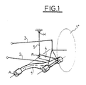
- the rear axle comprises a hydraulic shock absorber 6, a helical suspension spring 7 which can also be an air spring, a lower rod 2 of camber, a longitudinal arm 1, an upper connecting rod 3 camber.
- a transverse blade 4 is fixed by one of its ends on the longitudinal arm 1 and cooperates by its other end with a substantially vertical link 5.
- the lower and upper ends of the link 5 are respectively articulated on the blade 4 and the chassis.
- the corresponding joints are pivot type.
- the shock absorber 6, the lower 2 and upper 3 connecting rods camber as well as the longitudinal arm 1 are mounted in articulation between a stub axle 8 supporting the rear wheel left 1 'of the vehicle and the vehicle chassis.
- the arrow indicates the direction of movement of the moving vehicle before.
- the posterior end of the longitudinal arm 1 has a joint of revolution around a horizontal axis integral with the stub axle 8.
- the rear axle according to the invention has four points of fixing relative to the chassis. These attachment points are constituted by the front end of the longitudinal arm 1, a end of the lower camber rod 2, one end of the upper camber rod 3 and the upper end of the link 5.
- the longitudinal arm 1 has its front end mounted articulated on the vehicle chassis. Mounting can be carried out by means of an elastic bearing 9. The rear end part of the longitudinal arm 1 pivots in two points and around a substantially horizontal axis and inclined relative to the longitudinal direction secured to the rocket carrier 8.
- the center of the wheel 1 ' is located on the rear spindle axis or rear axle. This axis is horizontal and transverse to the vehicle.
- the front end of the longitudinal lower arm 1 is located further inside the vehicle in the transverse direction by relative to its rear end and has some cubit.
- the damper 6 inclined in a plane substantially transverse, with its upper end hinged on the chassis and its lower end hinged on the stub axle 8.
- the connecting rods 2 and 3 are articulated on the chassis and on the stub axle 8 in order to adjust the inclination of the plane of wheel with respect to the vertical.
- This inclination of the wheel plane 1 ' can be adjusted by modifying the relative provisions of the lower rods 2 and superior 3 to each other, which can be either by changing their respective length or the position of their respective articulation point on the chassis.
- the upper rod 3 carries the coil spring 7 or pneumatic suspension.
- the connecting rod 3 is provided with a cylindrical recess which receives the end lower end of spring 7, upper end of spring 7 being supported on the vehicle chassis.
- the connecting rod upper 3 carrier is arranged in a plane substantially horizontal and is articulated on the one hand on the chassis and on the other hand on the stub axle 8.
- the link 5 and the blade 4 are only slightly stressed, the main part of the longitudinal component of the forces applied to the wheel 1 'being taken up by the front articulation 9 of the longitudinal arm 1 on the chassis, the component transverse of said efforts being, for its part, level of the articulations of the connecting rods 2 and 3 on the chassis and the front articulation 9 of the longitudinal arm 1 previously cited.
- the train according to the invention makes it possible to adjust independently variations in the clamp and camber of the wheel plane 1 ' during the deflection of the latter during taxiing, the latter being controlled by an operation kinematics involving different elements of the rear axle.
- clamp variation law is determined by the obliquity of the virtual pivot axis of the wheel by compared to the chassis.
- This virtual hinge is made up by the right passing by the point A of articulation of the arm longitudinal 1 on the frame, on the one hand, and through the center P joint joint to link 5 and blade transverse 4, on the other hand.
- the connecting axes of the link 5 on the structure of the vehicle and on the blade 4 extend substantially longitudinally.
- the position of the center P of the joint common to the link 5 and to the blade 4 is by against easily changeable either by changing the length of the link 5 and of the blade 4, either by providing different adjustment holes arranged over all or part of the length of the blade 4, the axis of the joint common to the link 5 and to the blade 4 which can be mounted in either of these holes, allowing you to easily change the position of the point P.
- This point P varies very little compared to a point linked to the chassis during the running of the vehicle.
- the lower end of the link 5 is shaped as a fork with two branches between which is housed the corresponding end of the blade 4.
- the two branches of the fork are drilled with holes receiving the ends of an axis carried by the end of the blade 4.
- the upper end of the shock absorber 6 is mounted at pivoting on the vehicle structure around an axis coaxial with the mounting axis of the link 5 on the structure of the vehicle.
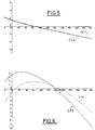
- Figure 6 shows the curves representative of the gripper variation for travel given of the wheel corresponding to two positions of the virtual axis of pivoting of the wheel relative to the frame.
- the first curve denoted CP1 corresponds to a first positioning of this hinge, and the second denoted CP2 at a second positioning defined with respect to to the first by moving up the point 2 mm arm articulation.
- Figure 5 shows the camber variation CC1, CC2 corresponding to the two particular positions of the virtual hinge respectively determining the laws of variation of clamp CP1, CP2.
- the rear axle according to the present invention further allows to make vehicles with a low overhang, and on which can be mounted large wheels diameter.
Landscapes
- Engineering & Computer Science (AREA)
- Mechanical Engineering (AREA)
- Vehicle Body Suspensions (AREA)
Description
La présente invention concerne un train arrière à roues indépendantes pour véhicule automobile.The present invention relates to a rear wheeled train independent for motor vehicle.
La publication ATZ 83(1991) 5, pages 274-280, décrit un train arrière comprenant un bras longitudinal dont l'extrémité antérieure est articulée sur le châssis et dont l'extrémité postérieure porte la fusée de roue. L'extrémité postérieure du bras longitudinal est reliée au châssis du véhciule par deux bras transversaux convergents.The publication ATZ 83 (1991) 5, pages 274-280, describes a rear axle comprising a longitudinal arm of which the anterior end is articulated on the chassis and whose the rear end carries the wheel knuckle. The end posterior of the longitudinal arm is connected to the chassis of the vehicle by two converging transverse arms.
La droite passant par le point de convergence des bras transversaux, d'une part, et le point avant d'articulation du bras longitudinal sur le châssis constitue l'axe de pivotement instantané de la roue par rapport au châssis. Cette charnière virtuelle détermine complètement les variations de pincement et de carrossage de la roue lors de son débattement. Les angles d'ouverture/fermeture et de carrossage de la roue, notamment, sont déterminés par la position relative du point de convergence des bras transversaux et du point d'articulation du bras longitudinal sur le châssis.The straight line passing through the point of convergence of the arms on the one hand, and the front point of articulation of the longitudinal arm on the chassis constitutes the pivot axis snapshot of the wheel in relation to the chassis. This hinge virtual completely determines the variations of pinching and camber of the wheel during its travel. The opening / closing angles and wheel camber, in particular, are determined by the relative position of the point of convergence of the arms transverse and the point of articulation of the longitudinal arm on the chassis.
Il en résulte que toute modification de la position relative de ces points, qui ne peut d'ailleurs s'effectuer que dans un domaine limité si l'on souhaite conserver au véhicule un comportement dynamique acceptable, entraíne une variation conjointe de ces angles.It follows that any change in the relative position of these points, which can only be done in a limited area if you want to keep the vehicle a acceptable dynamic behavior, causes variation joint of these angles.
La technique proposée dans ce document présente l'inconvénient que les angles de carrossage et de pince ne peuvent être réglés indépendamment l'un de l'autre. The technique proposed in this document presents the disadvantage that the camber and clamp angles do not can be set independently of each other.
Une telle disposition limite donc les possibilités d'évolution et de modification des caractéristiques de la suspension.Such a provision therefore limits the possibilities of evolution and modification of the characteristics of the suspension.
Un tel type de train nécessite en outre une conformation de caisse spécifique, ce qui rend très difficile son implantation sur un véhicule qui n'a pas été étudié pour le recevoir dès l'origine.Such a type of train also requires a conformation of specific body, which makes it very difficult to set up on a vehicle that has not been designed to receive it as soon as the origin.
Le document JP-A-5 278421 décrit un train arrière à roues indépendantes pour véhicule automobile, du type comprenant un porte-fusée de roue relié à la structure du véhicule par un bras longitudinal et une bielle supérieure de carrossage, un amortisseur et un ressort de suspension où la partie postérieure du bras longitudinal est relié à la structure du véhicule par une bielle inférieure de carrossage.Document JP-A-5 278421 describes a rear wheeled train independent for motor vehicle, of the type comprising a steering knuckle connected to the structure of the vehicle by a longitudinal arm and an upper connecting rod camber, a shock absorber and a suspension spring where the posterior part of the longitudinal arm is connected to the structure of the vehicle by a lower connecting rod camber.
Le document JP-A-60 033112 décrit une structure particulière de train arrière dans laquelle une extension est fixée sur le bras longitudinal, et une biellette est reliée à l'extension et à la structure du véhicule.Document JP-A-60 033112 describes a structure particular rear axle in which an extension is fixed on the longitudinal arm, and a link is connected to extension and structure of the vehicle.
Néanmoins, la structure de la suspension décrite dans le document JP-A-60 033112 est tout à fait différente de celle décrite dans le document JP-A-5 278421, si bien que l'inclusion de la caractéristique décrite dans le document JP-A-60 033112 présente de nombreuses difficultés.However, the structure of the suspension described in document JP-A-60 033112 is quite different from that described in document JP-A-5 278421, so that inclusion of the feature described in the document JP-A-60 033112 presents many difficulties.
La présente invention a pour objet une structure particulière de train arrière de véhicule automobile, qui pallie les inconvénients connus de l'état de la technique. The subject of the present invention is a particular structure rear axle of a motor vehicle, which overcomes the known drawbacks of the state of the art.
L'invention propose un train arrière dont l'angle de pince et de carrossage peuvent être réglés sensiblement indépendamment l'un de l'autre.The invention provides a rear axle whose clamp angle and camber can be adjusted significantly independently of each other.
En particulier, toute variation, tout du moins dans un domaine déterminé, de l'un des angles n'entraíne qu'une variation faible de l'autre, de telle sorte que l'on puisse considérer ces variations comme découplées.In particular, any variation, at least in a determined area, from one of the angles results in only one small variation of the other, so that we can consider these variations as decoupled.
Un autre avantage du train selon l'invention est qu'il est aisément adaptable sur des châssis différents au prix de modifications mineures et peut donc équiper tout ou partie d'une gamme d'un constructeur, d'où une économie d'échelle conséquente.Another advantage of the train according to the invention is that it is easily adaptable to different chassis at the price of minor modifications and can therefore equip all or part a range of a manufacturer, resulting in savings of consistent scale.
On comprendra mieux les buts, aspects et caractéristiques de la présente invention, d'après la description donnée ci-après d'un mode de réalisation de l'invention, présenté à titre d'exemple non limitatif, en se référant aux dessins annexés, dans lesquels :
- la figure 1 est une représentation schématique d'un demi-train selon l'invention,
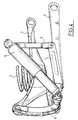
- la figure 2 est une vue en perspective d'un mode de réalisation d'un demi-train selon l'invention,
- la figure 3 est une vue de l'arrière du demi-train de la figure 2,
- la figure 4 est une vue de côté du demi-train de la figure 2.
- les figures 5 et 6 représentent respectivement les courbes d'évolution CC1, CC2 de l'angle de carrossage et les courbes d'évolution CP1, CP2 de l'angle de pince pour deux positionnements particuliers des éléments constitutifs du train arrière selon l'invention.
- FIG. 1 is a schematic representation of a half-train according to the invention,
- FIG. 2 is a perspective view of an embodiment of a half-train according to the invention,
- FIG. 3 is a view of the rear of the half-train of FIG. 2,
- FIG. 4 is a side view of the half-train of FIG. 2.
- Figures 5 and 6 show respectively the evolution curves CC1, CC2 of the camber angle and the evolution curves CP1, CP2 of the clamp angle for two particular positions of the components of the rear axle according to the invention .
Tel qu'illustré sur les figures 1 à 4, le train arrière selon
l'invention comprend un amortisseur 6 hydraulique, un
ressort 7 hélicoïdal de suspension qui peut être également
un ressort pneumatique, une bielle inférieure 2 de
carrossage, un bras longitudinal 1, une bielle supérieure 3
de carrossage.As illustrated in FIGS. 1 to 4, the rear axle according to
the invention comprises a
Une lame transversale 4 est fixée par l'une de ses
extrémités sur le bras longitudinal 1 et coopère par son
autre extrémité avec une biellette 5 sensiblement verticale.
Les extrémités inférieure et supérieure de la biellette 5 sont
respectivement articulées sur la lame 4 et le châssis. De
manière préférentielle, les articulations correspondantes
sont de type pivot. A
L'amortisseur 6, les bielles inférieure 2 et supérieure 3 de
carrossage ainsi que le bras longitudinal 1 sont montés en
articulation entre un porte-fusée 8 supportant la roue arrière
gauche 1' du véhicule et le châssis du véhicule. La flèche
indique le sens de déplacement du véhicule en marche
avant. De manière préférentielle, l'extrémité postérieure du
bras longitudinal 1 présente une articulation de révolution
autour d'un axe horizontal solidaire du porte-fusée 8.The shock absorber 6, the lower 2 and upper 3 connecting rods
camber as well as the
Le train arrière selon l'invention présente quatre points de
fixation par rapport au châssis. Ces points de fixation sont
constitués par l'extrémité avant du bras longitudinal 1, une
extrémité de la bielle inférieure 2 de carrossage, une
extrémité de la bielle supérieure 3 de carrossage et
l'extrémité supérieure de la biellette 5.The rear axle according to the invention has four points of
fixing relative to the chassis. These attachment points are
constituted by the front end of the
Le bras longitudinal 1 présente son extrémité avant montée
de façon articulée sur le châssis du véhicule. Le montage
peut être effectué au moyen d'un palier élastique 9. La
partie d'extrémité arrière du bras longitudinal 1 pivote en
deux points et autour d'un axe sensiblement horizontal et
incliné par rapport à la direction longitudinale solidarisé au
porte-fusée 8.The
Le centre de la roue 1' est situé sur l'axe de fusée arrière ou axe du train arrière. Cet axe est horizontal et transversal au véhicule.The center of the wheel 1 'is located on the rear spindle axis or rear axle. This axis is horizontal and transverse to the vehicle.
L'extrémité avant du bras inférieur longitudinal 1 est située
plus à l'intérieur du véhicule dans le sens transversal par
rapport à son extrémité arrière et présente une partie
coudée.The front end of the longitudinal
L'amortisseur 6, incliné dans un plan sensiblement
tranversal, a son extrémité supérieure articulée sur le
châssis et son extrémité inférieure articulée sur le porte-fusée
8.The
Les bielles 2 et 3 de carrossage s'articulent sur le châssis et
sur le porte-fusée 8 afin d'ajuster l'inclinaison du plan de
roue par rapport à la verticale.The connecting
Cette inclinaison du plan de roue 1' peut être réglée en
modifiant les dispositions relatives des bielles inférieure 2 et
supérieure 3 l'une par rapport à l'autre, ce qui peut être
réalisée, soit en modifiant leur longueur respective, soit la
position de leur point d'articulation respectif sur le châssis.This inclination of the wheel plane 1 'can be adjusted by
modifying the relative provisions of the
Ainsi un déplacement vertical vers le haut du point
d'articulation de la bielle supérieure 3 sur le porte-fusée 8
par rapport à l'axe du train diminue la valeur de l'angle de
carrossage de la roue 1'.Thus a vertical displacement towards the top of the point
of articulation of the
La bielle supérieure 3 est porteuse du ressort hélicoïdal 7 ou
pneumatique de suspension. A cet effet, la bielle 3 est
pourvue d'un évidement cylindrique qui reçoit l'extrémité
inférieure du ressort 7, l'extrémité supérieure du ressort 7
étant en appui sur le châssis du véhicule. La bielle
supérieure 3 porteuse est disposée dans un plan
sensiblement horizontal et s'articule d'une part sur le
châssis et d'autre part sur le porte-fusée 8.The
La biellette 5 et la lame 4 ne sont que faiblement sollicitées,
l'essentiel de la composante longitudinale des efforts
appliqués à la roue 1' étant reprise par l'articulation avant 9
du bras longitudinal 1 sur le châssis, la composante
transversale desdits efforts étant, quant à elle reprise au
niveau des articulations des bielles 2 et 3 sur le châssis et de
l'articulation avant 9 du bras longitudinal 1 précédemment
citée. The
Le train selon l'invention permet de régler indépendamment les variations de pince et de carrossage du plan de roue 1' lors du débattement de cette dernière au cours du roulage, ces dernières étant commandées par un fonctionnement cinématique faisant intervenir des éléments différents du train arrière.The train according to the invention makes it possible to adjust independently variations in the clamp and camber of the wheel plane 1 ' during the deflection of the latter during taxiing, the latter being controlled by an operation kinematics involving different elements of the rear axle.
En effet, la loi de variation de pince est déterminée par l'obliquité de l'axe de pivotement virtuel de la roue par rapport au châssis. Cette charnière virtuelle est constituée par la droite passant par le point A d'articulation du bras longitudinal 1 sur le châssis, d'une part, et par le centre P de l'articulation commune à la biellette 5 et à la lame transversale 4, d'autre part.Indeed, the clamp variation law is determined by the obliquity of the virtual pivot axis of the wheel by compared to the chassis. This virtual hinge is made up by the right passing by the point A of articulation of the arm longitudinal 1 on the frame, on the one hand, and through the center P joint joint to link 5 and blade transverse 4, on the other hand.
Les axes de liaison de la biellette 5 sur la structure du
véhicule et sur la lame 4 s'étendent sensiblement
longitudinalement.The connecting axes of the
Si la position du point A d'articulation antérieur du bras
longitudinal 1 reste fixe, la position du centre P de
l'articulation commune à la biellette 5 et à la lame 4 est par
contre facilement modifiable soit en modifiant la longueur
de la biellette 5 et de la lame 4, soit en prévoyant différents
trous de réglage disposés sur tout ou partie de la longueur
de la lame 4, l'axe de l'articulation commune à la biellette 5
et à la lame 4 pouvant être monté dans l'un ou l'autre de ces
trous, ce qui permet de modifier facilement la position du
point P.If the position of point A of the anterior articulation of the arm
longitudinal 1 remains fixed, the position of the center P of
the joint common to the
La position de ce point P varie très peu par rapport à un point lié au châssis au cours du roulage du véhicule. The position of this point P varies very little compared to a point linked to the chassis during the running of the vehicle.
L'extrémité inférieure de la biellette 5 est conformée en une
fourche à deux branches entre lesquelles vient se loger
l'extrémité correspondante de la lame 4.The lower end of the
Les deux branches de la fourche sont percées de trous de
réception des extrémités d'un axe porté par l'extrémité de la
lame 4.The two branches of the fork are drilled with holes
receiving the ends of an axis carried by the end of the
L'extrémité supérieure de l'amortisseur 6 est montée à
pivotement sur la structure du véhicule autour d'un axe
coaxial à l'axe de montage de la biellette 5 sur la structure
du véhicule.The upper end of the
La loi de variation du carrossage lors du débattement de la roue en cours de roulage est, quant à elle, déterminée uniquement par le positionnement relatif des bielles inférieure et supérieure l'une par rapport à l'autre qui détermine un point de convergence ainsi que leurs longueurs respectives.The law of variation of the camber during the deflection of the wheel in motion is determined only by the relative positioning of the connecting rods lower and higher relative to each other which determines a point of convergence as well as their respective lengths.
Les variations respectives du carrossage et de la pince sont donc cinématiquement indépendantes l'une de l'autre et toute modification de l'une des lois n'aura pas d'influence sur l'autre loi de variation.The respective variations of the camber and the clamp are therefore kinematically independent of each other and any change to one of the laws will have no influence on the other law of variation.
Ce découplage des lois de variation entre elles est illustré
par les figures 5 et 6. La figure 6 représente les courbes
représentatives de la variation de pince pour un débattement
donné de la roue correspondant à deux positionnements de
l'axe virtuel de pivotement de la roue par rapport au
châssis. La première courbe notée CP1 correspond à un
premier positionnement de cette charnière, et la seconde
notée CP2 à un deuxième positionnement défini par rapport
au premier par un déplacement vers le haut du point
d'articulation du bras de 2 mm.This decoupling of the laws of variation between them is illustrated
by Figures 5 and 6. Figure 6 shows the curves
representative of the gripper variation for travel
given of the wheel corresponding to two positions of
the virtual axis of pivoting of the wheel relative to the
frame. The first curve denoted CP1 corresponds to a
first positioning of this hinge, and the second
denoted CP2 at a second positioning defined with respect to
to the first by moving up the
La figure 5 représente la variation de carrossage CC1, CC2 correspondant aux deux positionnements particuliers de la charnière virtuelle déterminant respectivement les lois de variation de pince CP1, CP2.Figure 5 shows the camber variation CC1, CC2 corresponding to the two particular positions of the virtual hinge respectively determining the laws of variation of clamp CP1, CP2.
Ces figures 5 et 6 illustrent l'indépendance des lois de
variation entre elles, on constate en effet la quasi
superposition des courbes représentatives CC 1 et CC2.These figures 5 and 6 illustrate the independence of the laws of
variation between them, we see indeed almost
superposition of the
Le train arrière selon la présente invention permet en outre de réaliser des véhicules présentant un faible porte-à-faux, et sur lequel peuvent être montées des roues de grand diamètre.The rear axle according to the present invention further allows to make vehicles with a low overhang, and on which can be mounted large wheels diameter.
Bien entendu, l'invention n'est nullement limitée au mode de réalisation décrit et illustré qui n'a été donné qu'à titre d'exemple.Of course, the invention is in no way limited to the mode of implementation described and illustrated which was given only as example.
Au contraire, l'invention comprend tous les équivalents techniques des moyens décrits ainsi que leurs combinaisons si celles-ci sont effectuées suivant son esprit comme décrit dans les revendications suivantes.On the contrary, the invention includes all equivalents techniques of the means described and their combinations if these are carried out according to his spirit as described in the following claims.
Claims (8)
- Rear axle assembly with independent wheels for an automotive vehicle, of the type comprising a hub carrier 8 for a wheel 1' connected to the vehicle structure by a longitudinal arm 1 and an upper camber adjusting rod 3, a shock absorber 6 and a suspension spring 7, the posterior part of the longitudinal arm 1 being connected to the vehicle structure by a lower camber adjusting rod 2, characterised in that the posterior part of the longitudinal arm 1 is moreover connected to the vehicle structure by an assembly composed of a mutually articulated blade 4 and tie rod 5, where the blade 4 is fixed onto the longitudinal arm 1 and extends substantially transversely.
- Rear axle assembly according to claim 1, characterised in that the tie rod 5 extends substantially vertically.
- Rear axle assembly according to any one of the preceding claims, characterised in that the tie rod 5 is mounted in a pivoting manner about a first and a second axle respectively carried by the vehicle structure and by the extremity of the blade 4 opposite to the longitudinal arm 1.
- Rear axle assembly according to any one of the preceding claims, characterised in that the axes of connection of the tie rod 5 onto the vehicle structure and onto the blade 4 extend substantially longitudinally.
- Rear axle assembly according to any one of the preceding claims, characterised in that the lower extremity of the tie rod 5 is configured as a fork with two prongs, between which the corresponding extremity of the blade 4 comes to be accommodated.
- Rear axle assembly according to claim 5, characterised in that the two prongs of the fork are pierced by receiving apertures for the extremities of an axle carried by the extremity of the blade 4.
- Rear axle assembly according to any one of the preceding claims, characterised in that the upper extremity of the shock absorber 6 is mounted in a pivoting manner on the vehicle structure about an axle coaxial to the axis of mounting of the tie rod 5 on the vehicle structure.
- Rear axle assembly according to any one of the preceding claims, characterised in that the suspension spring 7 is mounted between the upper camber adjusting rod 3 and the vehicle structure.
Applications Claiming Priority (3)
| Application Number | Priority Date | Filing Date | Title |
|---|---|---|---|
| FR9608066 | 1996-06-28 | ||
| FR9608066A FR2750364B1 (en) | 1996-06-28 | 1996-06-28 | REAR TRAIN FOR MOTOR VEHICLE |
| PCT/FR1997/001156 WO1998000300A1 (en) | 1996-06-28 | 1997-06-27 | Rear axle assembly for motor vehicle |
Publications (2)
| Publication Number | Publication Date |
|---|---|
| EP0907520A1 EP0907520A1 (en) | 1999-04-14 |
| EP0907520B1 true EP0907520B1 (en) | 2001-08-29 |
Family
ID=9493521
Family Applications (1)
| Application Number | Title | Priority Date | Filing Date |
|---|---|---|---|
| EP97930609A Expired - Lifetime EP0907520B1 (en) | 1996-06-28 | 1997-06-27 | Rear axle assembly for motor vehicle |
Country Status (5)
| Country | Link |
|---|---|
| EP (1) | EP0907520B1 (en) |
| DE (1) | DE69706422T2 (en) |
| ES (1) | ES2160356T3 (en) |
| FR (1) | FR2750364B1 (en) |
| WO (1) | WO1998000300A1 (en) |
Families Citing this family (2)
| Publication number | Priority date | Publication date | Assignee | Title |
|---|---|---|---|---|
| MY118375A (en) * | 1997-03-21 | 2004-10-30 | Honda Motor Co Ltd | Wheel suspension system |
| JP4138461B2 (en) * | 2002-11-22 | 2008-08-27 | 株式会社エフテック | Vehicle suspension |
Family Cites Families (9)
| Publication number | Priority date | Publication date | Assignee | Title |
|---|---|---|---|---|
| DE3047004A1 (en) * | 1980-12-13 | 1982-07-22 | Dr.Ing.H.C. F. Porsche Ag, 7000 Stuttgart | Motor vehicle rear wheel suspension - has component between wheel bracket and guide member allowing controlled hinging |
| JPH064368B2 (en) * | 1983-08-01 | 1994-01-19 | マツダ株式会社 | Car rear suspension |
| JPS63265710A (en) * | 1987-04-24 | 1988-11-02 | Mazda Motor Corp | Suspension device for vehicle |
| IT1212162B (en) * | 1987-12-30 | 1989-11-08 | Fiat Auto Spa | REAR SUSPENSION FOR VEHICLES OF THE TYPE WITH INDEPENDENT WHEELS AND TRANSVERSAL QUADRILATERS |
| JPH04297311A (en) * | 1991-01-31 | 1992-10-21 | Yamaha Motor Co Ltd | Suspension for vehicle |
| JPH04317809A (en) * | 1991-04-16 | 1992-11-09 | Honda Motor Co Ltd | Rear suspension for vehicle |
| JPH05278421A (en) * | 1992-04-02 | 1993-10-26 | Fuji Heavy Ind Ltd | Rear suspension of automobile |
| JP2949679B2 (en) * | 1992-07-17 | 1999-09-20 | 新東工業株式会社 | Method for manufacturing porous mold material |
| FR2695595B1 (en) * | 1992-09-15 | 1994-11-25 | Renault | Rear axle with independent wheels for motor vehicle. |
-
1996
- 1996-06-28 FR FR9608066A patent/FR2750364B1/en not_active Expired - Fee Related
-
1997
- 1997-06-27 ES ES97930609T patent/ES2160356T3/en not_active Expired - Lifetime
- 1997-06-27 WO PCT/FR1997/001156 patent/WO1998000300A1/en not_active Ceased
- 1997-06-27 EP EP97930609A patent/EP0907520B1/en not_active Expired - Lifetime
- 1997-06-27 DE DE69706422T patent/DE69706422T2/en not_active Expired - Lifetime
Also Published As
| Publication number | Publication date |
|---|---|
| WO1998000300A1 (en) | 1998-01-08 |
| EP0907520A1 (en) | 1999-04-14 |
| DE69706422D1 (en) | 2001-10-04 |
| DE69706422T2 (en) | 2002-06-13 |
| FR2750364A1 (en) | 1998-01-02 |
| ES2160356T3 (en) | 2001-11-01 |
| FR2750364B1 (en) | 1998-07-31 |
Similar Documents
| Publication | Publication Date | Title |
|---|---|---|
| EP1070609B1 (en) | Motor vehicle equipped with a system controlling wheel camber during cornering | |
| EP1578626B1 (en) | Wheel support device with three pivots, suspension device and vehicle comprising said support device | |
| FR2607756A1 (en) | REAR SUSPENSION FOR AUTOMOBILE | |
| FR2588217A1 (en) | INDEPENDENT REAR WHEEL SUSPENSION | |
| EP1610967B1 (en) | Flexible rear axle with a control column and corresponding vehicle | |
| FR2761007A1 (en) | WHEEL SUSPENSION SYSTEM | |
| EP0279135B1 (en) | Front wheel suspension and pivot assembly for a motor vehicle | |
| FR2733463A1 (en) | Vehicle rear suspension system | |
| FR2707926A1 (en) | Improved suspension device for the front wheel of a motor vehicle | |
| WO2003011620A1 (en) | Pneumatic front suspension assembly for industrial vehicle | |
| EP0930183A1 (en) | Rear suspension device of a motor vehicle | |
| FR2466379A1 (en) | SELF-CONTROLLED WHEEL TYPE TIMONRY | |
| FR2874354A1 (en) | SUSPENSION OF LEG TYPE | |
| EP0588694B1 (en) | Rear suspension for motor vehicle with independent wheels | |
| WO1998000300A1 (en) | Rear axle assembly for motor vehicle | |
| EP1673244A2 (en) | Motor vehicle steering axle | |
| FR2707560A1 (en) | Rear wheel and axle assembly for motor vehicle | |
| FR2855143A1 (en) | FLEXIBLE REAR AXLE WITH ACTUATOR AND CORRESPONDING VEHICLE | |
| EP0187072B1 (en) | Rear suspension of an automotive vehicle | |
| FR2750925A1 (en) | Horizontal suspension unit for vehicle wheels | |
| FR3055878A1 (en) | REAR TRAIN OF A VEHICLE, IN PARTICULAR A MOTOR VEHICLE | |
| EP4134255B1 (en) | Rear end of a motor vehicle, in particular with steering wheels | |
| EP0392891B1 (en) | Vehicle suspension system | |
| FR2674187A1 (en) | Device forming a suspension, particularly for the rear wheel of a motor vehicle | |
| EP0729876A1 (en) | Rear suspension for a motor vehicle |
Legal Events
| Date | Code | Title | Description |
|---|---|---|---|
| PUAI | Public reference made under article 153(3) epc to a published international application that has entered the european phase |
Free format text: ORIGINAL CODE: 0009012 |
|
| 17P | Request for examination filed |
Effective date: 19981217 |
|
| AK | Designated contracting states |
Kind code of ref document: A1 Designated state(s): DE ES GB IT |
|
| 17Q | First examination report despatched |
Effective date: 19990325 |
|
| GRAG | Despatch of communication of intention to grant |
Free format text: ORIGINAL CODE: EPIDOS AGRA |
|
| GRAG | Despatch of communication of intention to grant |
Free format text: ORIGINAL CODE: EPIDOS AGRA |
|
| GRAH | Despatch of communication of intention to grant a patent |
Free format text: ORIGINAL CODE: EPIDOS IGRA |
|
| GRAH | Despatch of communication of intention to grant a patent |
Free format text: ORIGINAL CODE: EPIDOS IGRA |
|
| GRAA | (expected) grant |
Free format text: ORIGINAL CODE: 0009210 |
|
| AK | Designated contracting states |
Kind code of ref document: B1 Designated state(s): DE ES GB IT |
|
| ITF | It: translation for a ep patent filed | ||
| REF | Corresponds to: |
Ref document number: 69706422 Country of ref document: DE Date of ref document: 20011004 |
|
| REG | Reference to a national code |
Ref country code: ES Ref legal event code: FG2A Ref document number: 2160356 Country of ref document: ES Kind code of ref document: T3 |
|
| GBT | Gb: translation of ep patent filed (gb section 77(6)(a)/1977) |
Effective date: 20011018 |
|
| REG | Reference to a national code |
Ref country code: GB Ref legal event code: IF02 |
|
| PLBE | No opposition filed within time limit |
Free format text: ORIGINAL CODE: 0009261 |
|
| STAA | Information on the status of an ep patent application or granted ep patent |
Free format text: STATUS: NO OPPOSITION FILED WITHIN TIME LIMIT |
|
| 26N | No opposition filed | ||
| PGFP | Annual fee paid to national office [announced via postgrant information from national office to epo] |
Ref country code: GB Payment date: 20140618 Year of fee payment: 18 |
|
| PGFP | Annual fee paid to national office [announced via postgrant information from national office to epo] |
Ref country code: DE Payment date: 20140619 Year of fee payment: 18 Ref country code: ES Payment date: 20140627 Year of fee payment: 18 |
|
| PGFP | Annual fee paid to national office [announced via postgrant information from national office to epo] |
Ref country code: IT Payment date: 20140630 Year of fee payment: 18 |
|
| REG | Reference to a national code |
Ref country code: DE Ref legal event code: R119 Ref document number: 69706422 Country of ref document: DE |
|
| PG25 | Lapsed in a contracting state [announced via postgrant information from national office to epo] |
Ref country code: IT Free format text: LAPSE BECAUSE OF NON-PAYMENT OF DUE FEES Effective date: 20150627 |
|
| GBPC | Gb: european patent ceased through non-payment of renewal fee |
Effective date: 20150627 |
|
| PG25 | Lapsed in a contracting state [announced via postgrant information from national office to epo] |
Ref country code: GB Free format text: LAPSE BECAUSE OF NON-PAYMENT OF DUE FEES Effective date: 20150627 Ref country code: DE Free format text: LAPSE BECAUSE OF NON-PAYMENT OF DUE FEES Effective date: 20160101 |
|
| REG | Reference to a national code |
Ref country code: ES Ref legal event code: FD2A Effective date: 20160727 |
|
| PG25 | Lapsed in a contracting state [announced via postgrant information from national office to epo] |
Ref country code: ES Free format text: LAPSE BECAUSE OF NON-PAYMENT OF DUE FEES Effective date: 20150628 |