EP0907520B1 - Hinterachse für motorfahrzeug - Google Patents
Hinterachse für motorfahrzeug Download PDFInfo
- Publication number
- EP0907520B1 EP0907520B1 EP97930609A EP97930609A EP0907520B1 EP 0907520 B1 EP0907520 B1 EP 0907520B1 EP 97930609 A EP97930609 A EP 97930609A EP 97930609 A EP97930609 A EP 97930609A EP 0907520 B1 EP0907520 B1 EP 0907520B1
- Authority
- EP
- European Patent Office
- Prior art keywords
- rear axle
- axle assembly
- blade
- vehicle structure
- assembly according
- Prior art date
- Legal status (The legal status is an assumption and is not a legal conclusion. Google has not performed a legal analysis and makes no representation as to the accuracy of the status listed.)
- Expired - Lifetime
Links
- 239000000725 suspension Substances 0.000 claims description 7
- 239000006096 absorbing agent Substances 0.000 claims description 6
- 230000035939 shock Effects 0.000 claims description 6
- 210000003414 extremity Anatomy 0.000 claims 4
- 210000003141 lower extremity Anatomy 0.000 claims 1
- 210000001364 upper extremity Anatomy 0.000 claims 1
- 238000000034 method Methods 0.000 description 2
- 230000004048 modification Effects 0.000 description 2
- 238000012986 modification Methods 0.000 description 2
- 230000007423 decrease Effects 0.000 description 1
- 238000006073 displacement reaction Methods 0.000 description 1
Images


Classifications
-
- B—PERFORMING OPERATIONS; TRANSPORTING
- B60—VEHICLES IN GENERAL
- B60G—VEHICLE SUSPENSION ARRANGEMENTS
- B60G3/00—Resilient suspensions for a single wheel
- B60G3/18—Resilient suspensions for a single wheel with two or more pivoted arms, e.g. parallelogram
- B60G3/20—Resilient suspensions for a single wheel with two or more pivoted arms, e.g. parallelogram all arms being rigid
- B60G3/26—Means for maintaining substantially-constant wheel camber during suspension movement ; Means for controlling the variation of the wheel position during suspension movement
-
- B—PERFORMING OPERATIONS; TRANSPORTING
- B60—VEHICLES IN GENERAL
- B60G—VEHICLE SUSPENSION ARRANGEMENTS
- B60G2200/00—Indexing codes relating to suspension types
- B60G2200/10—Independent suspensions
- B60G2200/14—Independent suspensions with lateral arms
- B60G2200/141—Independent suspensions with lateral arms with one trailing arm and one lateral arm only
-
- B—PERFORMING OPERATIONS; TRANSPORTING
- B60—VEHICLES IN GENERAL
- B60G—VEHICLE SUSPENSION ARRANGEMENTS
- B60G2200/00—Indexing codes relating to suspension types
- B60G2200/10—Independent suspensions
- B60G2200/14—Independent suspensions with lateral arms
- B60G2200/144—Independent suspensions with lateral arms with two lateral arms forming a parallelogram
- B60G2200/1442—Independent suspensions with lateral arms with two lateral arms forming a parallelogram including longitudinal rods
-
- B—PERFORMING OPERATIONS; TRANSPORTING
- B60—VEHICLES IN GENERAL
- B60G—VEHICLE SUSPENSION ARRANGEMENTS
- B60G2200/00—Indexing codes relating to suspension types
- B60G2200/40—Indexing codes relating to the wheels in the suspensions
- B60G2200/462—Toe-in/out
-
- B—PERFORMING OPERATIONS; TRANSPORTING
- B60—VEHICLES IN GENERAL
- B60G—VEHICLE SUSPENSION ARRANGEMENTS
- B60G2202/00—Indexing codes relating to the type of spring, damper or actuator
- B60G2202/10—Type of spring
- B60G2202/12—Wound spring
-
- B—PERFORMING OPERATIONS; TRANSPORTING
- B60—VEHICLES IN GENERAL
- B60G—VEHICLE SUSPENSION ARRANGEMENTS
- B60G2204/00—Indexing codes related to suspensions per se or to auxiliary parts
- B60G2204/10—Mounting of suspension elements
- B60G2204/12—Mounting of springs or dampers
- B60G2204/124—Mounting of coil springs
-
- B—PERFORMING OPERATIONS; TRANSPORTING
- B60—VEHICLES IN GENERAL
- B60G—VEHICLE SUSPENSION ARRANGEMENTS
- B60G2204/00—Indexing codes related to suspensions per se or to auxiliary parts
- B60G2204/10—Mounting of suspension elements
- B60G2204/14—Mounting of suspension arms
- B60G2204/143—Mounting of suspension arms on the vehicle body or chassis
-
- B—PERFORMING OPERATIONS; TRANSPORTING
- B60—VEHICLES IN GENERAL
- B60G—VEHICLE SUSPENSION ARRANGEMENTS
- B60G2204/00—Indexing codes related to suspensions per se or to auxiliary parts
- B60G2204/10—Mounting of suspension elements
- B60G2204/14—Mounting of suspension arms
- B60G2204/148—Mounting of suspension arms on the unsprung part of the vehicle, e.g. wheel knuckle or rigid axle
-
- B—PERFORMING OPERATIONS; TRANSPORTING
- B60—VEHICLES IN GENERAL
- B60G—VEHICLE SUSPENSION ARRANGEMENTS
- B60G2206/00—Indexing codes related to the manufacturing of suspensions: constructional features, the materials used, procedures or tools
- B60G2206/01—Constructional features of suspension elements, e.g. arms, dampers, springs
- B60G2206/10—Constructional features of arms
- B60G2206/11—Constructional features of arms the arm being a radius or track or torque or steering rod or stabiliser end link
-
- B—PERFORMING OPERATIONS; TRANSPORTING
- B60—VEHICLES IN GENERAL
- B60G—VEHICLE SUSPENSION ARRANGEMENTS
- B60G2206/00—Indexing codes related to the manufacturing of suspensions: constructional features, the materials used, procedures or tools
- B60G2206/01—Constructional features of suspension elements, e.g. arms, dampers, springs
- B60G2206/10—Constructional features of arms
- B60G2206/121—Constructional features of arms the arm having an H or X-shape
-
- B—PERFORMING OPERATIONS; TRANSPORTING
- B60—VEHICLES IN GENERAL
- B60G—VEHICLE SUSPENSION ARRANGEMENTS
- B60G2206/00—Indexing codes related to the manufacturing of suspensions: constructional features, the materials used, procedures or tools
- B60G2206/01—Constructional features of suspension elements, e.g. arms, dampers, springs
- B60G2206/10—Constructional features of arms
- B60G2206/122—Constructional features of arms the arm having L-shape
Definitions
- the present invention relates to a rear wheeled train independent for motor vehicle.
- the straight line passing through the point of convergence of the arms on the one hand, and the front point of articulation of the longitudinal arm on the chassis constitutes the pivot axis snapshot of the wheel in relation to the chassis.
- This hinge virtual completely determines the variations of pinching and camber of the wheel during its travel.
- the opening / closing angles and wheel camber are determined by the relative position of the point of convergence of the arms transverse and the point of articulation of the longitudinal arm on the chassis.
- Such a type of train also requires a conformation of specific body, which makes it very difficult to set up on a vehicle that has not been designed to receive it as soon as the origin.
- Document JP-A-5 278421 describes a rear wheeled train independent for motor vehicle, of the type comprising a steering knuckle connected to the structure of the vehicle by a longitudinal arm and an upper connecting rod camber, a shock absorber and a suspension spring where the posterior part of the longitudinal arm is connected to the structure of the vehicle by a lower connecting rod camber.
- Document JP-A-60 033112 describes a structure particular rear axle in which an extension is fixed on the longitudinal arm, and a link is connected to extension and structure of the vehicle.
- the subject of the present invention is a particular structure rear axle of a motor vehicle, which overcomes the known drawbacks of the state of the art.
- the invention provides a rear axle whose clamp angle and camber can be adjusted significantly independently of each other.
- any variation, at least in a determined area, from one of the angles results in only one small variation of the other, so that we can consider these variations as decoupled.
- Another advantage of the train according to the invention is that it is easily adaptable to different chassis at the price of minor modifications and can therefore equip all or part a range of a manufacturer, resulting in savings of consistent scale.
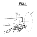
- the rear axle comprises a hydraulic shock absorber 6, a helical suspension spring 7 which can also be an air spring, a lower rod 2 of camber, a longitudinal arm 1, an upper connecting rod 3 camber.
- a transverse blade 4 is fixed by one of its ends on the longitudinal arm 1 and cooperates by its other end with a substantially vertical link 5.
- the lower and upper ends of the link 5 are respectively articulated on the blade 4 and the chassis.
- the corresponding joints are pivot type.
- the shock absorber 6, the lower 2 and upper 3 connecting rods camber as well as the longitudinal arm 1 are mounted in articulation between a stub axle 8 supporting the rear wheel left 1 'of the vehicle and the vehicle chassis.
- the arrow indicates the direction of movement of the moving vehicle before.
- the posterior end of the longitudinal arm 1 has a joint of revolution around a horizontal axis integral with the stub axle 8.
- the rear axle according to the invention has four points of fixing relative to the chassis. These attachment points are constituted by the front end of the longitudinal arm 1, a end of the lower camber rod 2, one end of the upper camber rod 3 and the upper end of the link 5.
- the longitudinal arm 1 has its front end mounted articulated on the vehicle chassis. Mounting can be carried out by means of an elastic bearing 9. The rear end part of the longitudinal arm 1 pivots in two points and around a substantially horizontal axis and inclined relative to the longitudinal direction secured to the rocket carrier 8.
- the center of the wheel 1 ' is located on the rear spindle axis or rear axle. This axis is horizontal and transverse to the vehicle.
- the front end of the longitudinal lower arm 1 is located further inside the vehicle in the transverse direction by relative to its rear end and has some cubit.
- the damper 6 inclined in a plane substantially transverse, with its upper end hinged on the chassis and its lower end hinged on the stub axle 8.
- the connecting rods 2 and 3 are articulated on the chassis and on the stub axle 8 in order to adjust the inclination of the plane of wheel with respect to the vertical.
- This inclination of the wheel plane 1 ' can be adjusted by modifying the relative provisions of the lower rods 2 and superior 3 to each other, which can be either by changing their respective length or the position of their respective articulation point on the chassis.
- the upper rod 3 carries the coil spring 7 or pneumatic suspension.
- the connecting rod 3 is provided with a cylindrical recess which receives the end lower end of spring 7, upper end of spring 7 being supported on the vehicle chassis.
- the connecting rod upper 3 carrier is arranged in a plane substantially horizontal and is articulated on the one hand on the chassis and on the other hand on the stub axle 8.
- the link 5 and the blade 4 are only slightly stressed, the main part of the longitudinal component of the forces applied to the wheel 1 'being taken up by the front articulation 9 of the longitudinal arm 1 on the chassis, the component transverse of said efforts being, for its part, level of the articulations of the connecting rods 2 and 3 on the chassis and the front articulation 9 of the longitudinal arm 1 previously cited.
- the train according to the invention makes it possible to adjust independently variations in the clamp and camber of the wheel plane 1 ' during the deflection of the latter during taxiing, the latter being controlled by an operation kinematics involving different elements of the rear axle.
- clamp variation law is determined by the obliquity of the virtual pivot axis of the wheel by compared to the chassis.
- This virtual hinge is made up by the right passing by the point A of articulation of the arm longitudinal 1 on the frame, on the one hand, and through the center P joint joint to link 5 and blade transverse 4, on the other hand.
- the connecting axes of the link 5 on the structure of the vehicle and on the blade 4 extend substantially longitudinally.
- the position of the center P of the joint common to the link 5 and to the blade 4 is by against easily changeable either by changing the length of the link 5 and of the blade 4, either by providing different adjustment holes arranged over all or part of the length of the blade 4, the axis of the joint common to the link 5 and to the blade 4 which can be mounted in either of these holes, allowing you to easily change the position of the point P.
- This point P varies very little compared to a point linked to the chassis during the running of the vehicle.
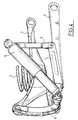
- the lower end of the link 5 is shaped as a fork with two branches between which is housed the corresponding end of the blade 4.
- the two branches of the fork are drilled with holes receiving the ends of an axis carried by the end of the blade 4.
- the upper end of the shock absorber 6 is mounted at pivoting on the vehicle structure around an axis coaxial with the mounting axis of the link 5 on the structure of the vehicle.
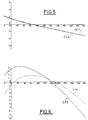
- Figure 6 shows the curves representative of the gripper variation for travel given of the wheel corresponding to two positions of the virtual axis of pivoting of the wheel relative to the frame.
- the first curve denoted CP1 corresponds to a first positioning of this hinge, and the second denoted CP2 at a second positioning defined with respect to to the first by moving up the point 2 mm arm articulation.
- Figure 5 shows the camber variation CC1, CC2 corresponding to the two particular positions of the virtual hinge respectively determining the laws of variation of clamp CP1, CP2.
- the rear axle according to the present invention further allows to make vehicles with a low overhang, and on which can be mounted large wheels diameter.
Landscapes
- Engineering & Computer Science (AREA)
- Mechanical Engineering (AREA)
- Vehicle Body Suspensions (AREA)
Claims (8)
- Hinterachsaggregat mit unabhängigen Rädern für ein Automobil, umfassend einen Achsschenkel (8) eines Rades (1'), der mit der Struktur des Fahrzeugs durch einen Längsarm (1) und eine obere Sturzstange (3), einen Stoßdämpfer (6) und eine Aufhängungsfeder (7) verbunden ist, wobei der hintere Teil des Längsarms (1) mit der Struktur des Fahrzeugs durch eine untere Sturzstange (2), verbunden ist, dadurch gekennzeichnet, dass der hintere Teil des Längsarms (1) darüber hinaus mit der Struktur des Fahrzeugs durch eine Einheit verbunden ist, die sich zusammensetzt aus einem Blatt (4) und einem Schwingarm (5), die gelenkig miteinander verbunden sind, wobei das Blatt 4 am Längsarm (1) befestigt ist und sich annähernd in Querrichtung erstreckt.
- Hinterachsaggregat nach Anspruch 1, dadurch gekennzeichnet, dass sich der Schwingarm (5) annähernd vertikal erstreckt.
- Hinterachsaggregat nach einem der vorhergehenden Ansprüche, dadurch gekennzeichnet, dass der Schwingarm (5) um eine erste und eine zweite Achse schwenkbar montiert ist, die von der Struktur des Fahrzeugs bzw. von dem Ende des Blattes (4), das dem Längsarm (1) entgegengesetzt ist, getragen werden.
- Hinterachsaggregat nach einem der vorhergehenden Ansprüche, dadurch gekennzeichnet, dass die sich Achsen der Verbindung des Schwingarms (5) mit der Struktur des Fahrzeugs und mit dem Blatt 4 annähernd in Längsrichtung erstrecken.
- Hinterachsaggregat nach einem der vorhergehenden Ansprüche, dadurch gekennzeichnet, dass das untere Ende des Schwingarms die Form einer Gabel mit zwei Zweigen aufweist, zwischen denen das entsprechende Ende des Blattes (4) aufgenommen wird.
- Hinterachsaggregat nach Anspruch 5, dadurch gekennzeichnet, dass in die zwei Zweige der Gabel Löcher zur Aufnahme der Enden einer Achse gebohrt sind, die vom Ende des Blattes (4) getragen wird.
- Hinterachsaggregat nach einem der vorhergehenden Ansprüche, dadurch gekennzeichnet, dass das obere Ende des Stoßdämpfers (6) an der Struktur des Fahrzeugs schwenkbar um eine Achse montiert ist, die koaxial mit der Achse der Montage des Schwingarms (5) an der Struktur des Fahrzeugs ist.
- Hinterachsaggregat nach einem der vorhergehenden Ansprüche, dadurch gekennzeichnet, dass die Aufhängungsfeder (7) zwischen der oberen Sturzstange (3) und der Struktur des Fahrzeugs montiert ist.
Applications Claiming Priority (3)
| Application Number | Priority Date | Filing Date | Title |
|---|---|---|---|
| FR9608066 | 1996-06-28 | ||
| FR9608066A FR2750364B1 (fr) | 1996-06-28 | 1996-06-28 | Train arriere pour vehicule automobile |
| PCT/FR1997/001156 WO1998000300A1 (fr) | 1996-06-28 | 1997-06-27 | Train arriere pour vehicule automobile |
Publications (2)
| Publication Number | Publication Date |
|---|---|
| EP0907520A1 EP0907520A1 (de) | 1999-04-14 |
| EP0907520B1 true EP0907520B1 (de) | 2001-08-29 |
Family
ID=9493521
Family Applications (1)
| Application Number | Title | Priority Date | Filing Date |
|---|---|---|---|
| EP97930609A Expired - Lifetime EP0907520B1 (de) | 1996-06-28 | 1997-06-27 | Hinterachse für motorfahrzeug |
Country Status (5)
| Country | Link |
|---|---|
| EP (1) | EP0907520B1 (de) |
| DE (1) | DE69706422T2 (de) |
| ES (1) | ES2160356T3 (de) |
| FR (1) | FR2750364B1 (de) |
| WO (1) | WO1998000300A1 (de) |
Families Citing this family (2)
| Publication number | Priority date | Publication date | Assignee | Title |
|---|---|---|---|---|
| MY118375A (en) * | 1997-03-21 | 2004-10-30 | Honda Motor Co Ltd | Wheel suspension system |
| JP4138461B2 (ja) * | 2002-11-22 | 2008-08-27 | 株式会社エフテック | 車両用サスペンション |
Family Cites Families (9)
| Publication number | Priority date | Publication date | Assignee | Title |
|---|---|---|---|---|
| DE3047004A1 (de) * | 1980-12-13 | 1982-07-22 | Dr.Ing.H.C. F. Porsche Ag, 7000 Stuttgart | Hinterradaufhaengung fuer kraftfahrzeuge, insbesondere doppelquerlenkeraufhaengung |
| JPH064368B2 (ja) * | 1983-08-01 | 1994-01-19 | マツダ株式会社 | 自動車のリヤサスペンション |
| JPS63265710A (ja) * | 1987-04-24 | 1988-11-02 | Mazda Motor Corp | 車両のサスペンシヨン装置 |
| IT1212162B (it) * | 1987-12-30 | 1989-11-08 | Fiat Auto Spa | Sospensione posteriore per autoveicoli del tipo a ruote indipendenti a quadrilateri trasversali |
| JPH04297311A (ja) * | 1991-01-31 | 1992-10-21 | Yamaha Motor Co Ltd | 車両の懸架装置 |
| JPH04317809A (ja) * | 1991-04-16 | 1992-11-09 | Honda Motor Co Ltd | 車両用リヤサスペンション |
| JPH05278421A (ja) * | 1992-04-02 | 1993-10-26 | Fuji Heavy Ind Ltd | 自動車のリヤサスペンション |
| JP2949679B2 (ja) * | 1992-07-17 | 1999-09-20 | 新東工業株式会社 | 多孔質金型材の製造方法 |
| FR2695595B1 (fr) * | 1992-09-15 | 1994-11-25 | Renault | Train arrière à roues indépendantes pour véhicule automobile. |
-
1996
- 1996-06-28 FR FR9608066A patent/FR2750364B1/fr not_active Expired - Fee Related
-
1997
- 1997-06-27 ES ES97930609T patent/ES2160356T3/es not_active Expired - Lifetime
- 1997-06-27 DE DE69706422T patent/DE69706422T2/de not_active Expired - Lifetime
- 1997-06-27 WO PCT/FR1997/001156 patent/WO1998000300A1/fr not_active Ceased
- 1997-06-27 EP EP97930609A patent/EP0907520B1/de not_active Expired - Lifetime
Also Published As
| Publication number | Publication date |
|---|---|
| FR2750364B1 (fr) | 1998-07-31 |
| ES2160356T3 (es) | 2001-11-01 |
| DE69706422D1 (de) | 2001-10-04 |
| FR2750364A1 (fr) | 1998-01-02 |
| DE69706422T2 (de) | 2002-06-13 |
| EP0907520A1 (de) | 1999-04-14 |
| WO1998000300A1 (fr) | 1998-01-08 |
Similar Documents
| Publication | Publication Date | Title |
|---|---|---|
| EP1070609B1 (de) | Kraftfahrzeug ausgerüstet mit einem System zur Radsturzsteuerung bei Kurvenfahrten | |
| EP1578626B1 (de) | Radträgervorrichtung mit dreifachscharnier, aufhängungsvorrichtung und kraftfahrzeug mit einer solchen trägervorrichtung | |
| FR2607756A1 (fr) | Suspension arriere pour automobile | |
| EP0458665B1 (de) | Hinterradaufhängung eines Kraftfahrzeugs | |
| FR2588217A1 (fr) | Suspension de roue arriere independante | |
| EP1610967B1 (de) | Flexible hinterachse mit einer steuersäule und entsprechendes fahrzeug | |
| EP0279135B1 (de) | Aufhängungs- und Schwenkvorrichtung von einem lenkbaren Rad eines Kraftfahrzeuges | |
| FR2733463A1 (fr) | Systeme de suspension arriere pour vehicule | |
| FR2707926A1 (fr) | Dispositif de suspension perfectionné pour une roue avant de véhicule automobile. | |
| FR2855459A1 (fr) | Essieu souple arriere a actionneurs et vehicule correspondant | |
| EP1412210A1 (de) | Pneumatische vorderradaufhängungsanordnung für industriefahrzeug | |
| EP0930183A1 (de) | Hinterradaufhängungsvorrichtung eines Kraftfahrzeuges | |
| EP0907520B1 (de) | Hinterachse für motorfahrzeug | |
| FR2466379A1 (fr) | Timonerie du type a bielle de commande de direction laterale | |
| FR2874354A1 (fr) | Suspension du type a jambe | |
| EP0588694B1 (de) | Hinterradaufhängung für Kraftfahrzeug mit unabhängigen Rädern | |
| EP1673244A2 (de) | Kraftfahrzeuglenkachse | |
| FR2707560A1 (fr) | Train de roues arrière pour véhicule automobile. | |
| FR2855143A1 (fr) | Essieu souple arriere a actionneur et vehicule correspondant | |
| EP0187072B1 (de) | Hinterradaufhängung eines Kraftfahrzeugs | |
| FR2750925A1 (fr) | Suspension horizontale pour roue de vehicule automobile avec systeme de filtrage des chocs longitudinaux | |
| FR3055878A1 (fr) | Train arriere d'un vehicule, notamment automobile | |
| EP4134255B1 (de) | Hinterachse eines kraftfahrzeugs, insbesondere mit gelenkten rädern | |
| EP0392891B1 (de) | Radaufhängung für Kraftfahrzeuge | |
| FR2674187A1 (fr) | Dispositif formant suspension notamment de roue arriere d'un vehicule automobile. |
Legal Events
| Date | Code | Title | Description |
|---|---|---|---|
| PUAI | Public reference made under article 153(3) epc to a published international application that has entered the european phase |
Free format text: ORIGINAL CODE: 0009012 |
|
| 17P | Request for examination filed |
Effective date: 19981217 |
|
| AK | Designated contracting states |
Kind code of ref document: A1 Designated state(s): DE ES GB IT |
|
| 17Q | First examination report despatched |
Effective date: 19990325 |
|
| GRAG | Despatch of communication of intention to grant |
Free format text: ORIGINAL CODE: EPIDOS AGRA |
|
| GRAG | Despatch of communication of intention to grant |
Free format text: ORIGINAL CODE: EPIDOS AGRA |
|
| GRAH | Despatch of communication of intention to grant a patent |
Free format text: ORIGINAL CODE: EPIDOS IGRA |
|
| GRAH | Despatch of communication of intention to grant a patent |
Free format text: ORIGINAL CODE: EPIDOS IGRA |
|
| GRAA | (expected) grant |
Free format text: ORIGINAL CODE: 0009210 |
|
| AK | Designated contracting states |
Kind code of ref document: B1 Designated state(s): DE ES GB IT |
|
| ITF | It: translation for a ep patent filed | ||
| REF | Corresponds to: |
Ref document number: 69706422 Country of ref document: DE Date of ref document: 20011004 |
|
| REG | Reference to a national code |
Ref country code: ES Ref legal event code: FG2A Ref document number: 2160356 Country of ref document: ES Kind code of ref document: T3 |
|
| GBT | Gb: translation of ep patent filed (gb section 77(6)(a)/1977) |
Effective date: 20011018 |
|
| REG | Reference to a national code |
Ref country code: GB Ref legal event code: IF02 |
|
| PLBE | No opposition filed within time limit |
Free format text: ORIGINAL CODE: 0009261 |
|
| STAA | Information on the status of an ep patent application or granted ep patent |
Free format text: STATUS: NO OPPOSITION FILED WITHIN TIME LIMIT |
|
| 26N | No opposition filed | ||
| PGFP | Annual fee paid to national office [announced via postgrant information from national office to epo] |
Ref country code: GB Payment date: 20140618 Year of fee payment: 18 |
|
| PGFP | Annual fee paid to national office [announced via postgrant information from national office to epo] |
Ref country code: DE Payment date: 20140619 Year of fee payment: 18 Ref country code: ES Payment date: 20140627 Year of fee payment: 18 |
|
| PGFP | Annual fee paid to national office [announced via postgrant information from national office to epo] |
Ref country code: IT Payment date: 20140630 Year of fee payment: 18 |
|
| REG | Reference to a national code |
Ref country code: DE Ref legal event code: R119 Ref document number: 69706422 Country of ref document: DE |
|
| PG25 | Lapsed in a contracting state [announced via postgrant information from national office to epo] |
Ref country code: IT Free format text: LAPSE BECAUSE OF NON-PAYMENT OF DUE FEES Effective date: 20150627 |
|
| GBPC | Gb: european patent ceased through non-payment of renewal fee |
Effective date: 20150627 |
|
| PG25 | Lapsed in a contracting state [announced via postgrant information from national office to epo] |
Ref country code: GB Free format text: LAPSE BECAUSE OF NON-PAYMENT OF DUE FEES Effective date: 20150627 Ref country code: DE Free format text: LAPSE BECAUSE OF NON-PAYMENT OF DUE FEES Effective date: 20160101 |
|
| REG | Reference to a national code |
Ref country code: ES Ref legal event code: FD2A Effective date: 20160727 |
|
| PG25 | Lapsed in a contracting state [announced via postgrant information from national office to epo] |
Ref country code: ES Free format text: LAPSE BECAUSE OF NON-PAYMENT OF DUE FEES Effective date: 20150628 |