EP0907147A2 - Procédé d'affichage de séquences vidéo et dispositif d'affichage - Google Patents
Procédé d'affichage de séquences vidéo et dispositif d'affichage Download PDFInfo
- Publication number
- EP0907147A2 EP0907147A2 EP98307789A EP98307789A EP0907147A2 EP 0907147 A2 EP0907147 A2 EP 0907147A2 EP 98307789 A EP98307789 A EP 98307789A EP 98307789 A EP98307789 A EP 98307789A EP 0907147 A2 EP0907147 A2 EP 0907147A2
- Authority
- EP
- European Patent Office
- Prior art keywords
- clips
- clip
- graphic representation
- segments
- motion picture
- Prior art date
- Legal status (The legal status is an assumption and is not a legal conclusion. Google has not performed a legal analysis and makes no representation as to the accuracy of the status listed.)
- Withdrawn
Links
- 238000000034 method Methods 0.000 title claims abstract description 75
- 239000013598 vector Substances 0.000 claims description 46
- 238000004364 calculation method Methods 0.000 claims description 29
- 239000003086 colorant Substances 0.000 claims description 19
- 238000000605 extraction Methods 0.000 claims description 11
- 238000010586 diagram Methods 0.000 description 20
- 238000013500 data storage Methods 0.000 description 3
- 239000000284 extract Substances 0.000 description 3
- 238000013507 mapping Methods 0.000 description 3
- 230000006835 compression Effects 0.000 description 2
- 238000007906 compression Methods 0.000 description 2
- 238000006243 chemical reaction Methods 0.000 description 1
- 238000001514 detection method Methods 0.000 description 1
- 239000006185 dispersion Substances 0.000 description 1
- 230000000694 effects Effects 0.000 description 1
- 238000007726 management method Methods 0.000 description 1
- 239000000463 material Substances 0.000 description 1
- 238000012986 modification Methods 0.000 description 1
- 230000004048 modification Effects 0.000 description 1
- 238000012544 monitoring process Methods 0.000 description 1
- 238000000926 separation method Methods 0.000 description 1
Images


Classifications
-
- G—PHYSICS
- G11—INFORMATION STORAGE
- G11B—INFORMATION STORAGE BASED ON RELATIVE MOVEMENT BETWEEN RECORD CARRIER AND TRANSDUCER
- G11B27/00—Editing; Indexing; Addressing; Timing or synchronising; Monitoring; Measuring tape travel
- G11B27/10—Indexing; Addressing; Timing or synchronising; Measuring tape travel
- G11B27/34—Indicating arrangements
-
- G—PHYSICS
- G11—INFORMATION STORAGE
- G11B—INFORMATION STORAGE BASED ON RELATIVE MOVEMENT BETWEEN RECORD CARRIER AND TRANSDUCER
- G11B27/00—Editing; Indexing; Addressing; Timing or synchronising; Monitoring; Measuring tape travel
- G11B27/02—Editing, e.g. varying the order of information signals recorded on, or reproduced from, record carriers
- G11B27/031—Electronic editing of digitised analogue information signals, e.g. audio or video signals
- G11B27/034—Electronic editing of digitised analogue information signals, e.g. audio or video signals on discs
-
- G—PHYSICS
- G11—INFORMATION STORAGE
- G11B—INFORMATION STORAGE BASED ON RELATIVE MOVEMENT BETWEEN RECORD CARRIER AND TRANSDUCER
- G11B27/00—Editing; Indexing; Addressing; Timing or synchronising; Monitoring; Measuring tape travel
- G11B27/10—Indexing; Addressing; Timing or synchronising; Measuring tape travel
- G11B27/19—Indexing; Addressing; Timing or synchronising; Measuring tape travel by using information detectable on the record carrier
- G11B27/28—Indexing; Addressing; Timing or synchronising; Measuring tape travel by using information detectable on the record carrier by using information signals recorded by the same method as the main recording
-
- G—PHYSICS
- G11—INFORMATION STORAGE
- G11B—INFORMATION STORAGE BASED ON RELATIVE MOVEMENT BETWEEN RECORD CARRIER AND TRANSDUCER
- G11B2220/00—Record carriers by type
- G11B2220/20—Disc-shaped record carriers
Definitions
- the present invention relates to a method whereby when editing a motion picture, loaded from a disk or a video camera, individual pieces of information of scenes can be displayed on an editing device, and to a display device for this purpose; and in particular, to a method for displaying material to be edited that facilitates the editing operation.
- a group of images for a scene one of a number of image groups obtained by dividing a series of images at predetermined time intervals, is called a clip.
- a typical image (index) for each clip can be displayed on an editing device, and an editor can then edit scenes while viewing these images.
- index the length of a clip for a scene can not be ascertained only from the index, editing is sometimes difficult.
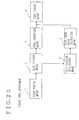
- a conventional display device to provide such a display comprises, as is shown in Fig. 20, video reading means 1, for reading digital images supplied by a video camera or a disk; clip division means 2, for dividing a series of digital images into clips; clip division data storage means 4, for maintaining IN point and OUT point data for the obtained clips; index generation means 3, for generating indexes for the clips; clip length ratio calculation means 5, for calculating the ratios for the lengths of the individual clips; and index display means 6, for displaying indexes by employing data received from the index generation means 3 and the clip length ratio calculation means 5.
- the clip division means 2 divides the digital images into clips.
- the index generation means 3 generates typical images, which are used as indexes, using the first frames of the individual obtained dips and outputs the stationary images to the index display means 6.
- the IN point and OUT point data for the clips are stored in the clip division data storage means 4.
- the clip length ratio calculation means 5 calculates the ratios for the lengths of the clips from the IN point and OUT point data, and outputs the ratio to the index display means 6.
- the index display means 6 Upon receipt of the data from the index generation means 3 and the clip length ratio calculation means 5, the index display means 6 displays the indexes for the clips and the ratios for the lengths of the clips using the form shown in Fig. 18 or 19.
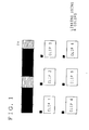
- a graphic representation for a motion picture is divided to provide segments corresponding to the ratio of the lengths of the clips to the total length of the motion picture, and presented are sequences of the separate graphic segments linked to typical images.
- a motion vector and a color change for a clip or a moving object in a motion picture is displayed in each corresponding segment of the graphic representation covering the overall length of the motion picture.
- the locations and the lengths of the individual clips, as they are related to the motion picture, or the contents of the images included in the clips, can be ascertained at a glance, and the editing can be performed very smoothly.
- a clip display device comprises: index display means, for displaying typical images of individual clips; clip length ratio display means, for dividing a graphic representation of the overall length of a motion picture into segments at the ratios of the lengths of the clips to the overall length of the motion picture; and linking means, for linking the typical images displayed by the index display means with the segments of the graphic representation displayed by the clip length ratio display means.
- the display device further comprises means for calculating, at a constant time interval, a motion vector from a motion picture; color data calculation means, for calculating at a constant time interval color data from a motion picture; and maximum movement object extraction means for extracting, at a constant time interval, an object that travels a maximum distance.
- the linking means links the thus obtained motion vector, the color data and the object that moves the maximum distance to the segments of the graphic representation that correspond to the overall length of the motion picture.
- the clip length ratio display means displays the items in the graphic segments that are linked together.
- This display device can employ the above described clip display method.
- a clip display method whereby clips obtained by dividing a motion picture are displayed using typical images of the clips, comprises the steps of
- the segments of the graphic representation are linked with the typical images by using colors or numerals. Since a segment having a color or a numeral provided for the typical image is searched for in the graphic representation of the overall length of the motion picture, the positioning in the motion picture of the clips represented by the typical images can be understood at a glance.
- a clip display method whereby clips obtained by dividing a motion picture are displayed using typical images of the clips, comprises the steps of
- a clip display method whereby clips obtained by dividing a motion picture are displayed using typical images of the clips, comprises the steps of
- a clip display method whereby clips obtained by dividing a motion picture are displayed using typical images of the clips, comprises the steps of
- the width or the type of line used for the border lines is changed in consonance with the numerical differential value. It can be ascertained that there is a large change of scene when a border line is thick, and that there is a small change of scene when a border line is thin. In addition, it can be ascertained that there is a large change of scene when a border line is represented by a solid line, and that there is a small change of scene when a border line is represented by a broken line.
- a clip display method whereby clips obtained by dividing a motion picture are displayed using typical images of the clips, comprises the steps of
- a clip display method whereby clips obtained by dividing a motion picture are displayed using typical images of the clips, comprises the steps of
- a mark is displayed in a corresponding segment of the graphic representation of the overall length of a motion picture, so that, when one location in the graphic representation of the overall length of the motion picture is selected, a corresponding typical image is displayed.
- the correspondence between a segment of the graphic representation of the overall length of the motion picture and a clip that is represented by a typical image can be ascertained at a glance.
- a clip display device which displays clips obtained by dividing a motion picture using typical images of the clips, comprises: index display means for displaying the typical images of clips; clip length ratio display means for dividing a graphic representation of the overall length of a motion picture into segments at ratios of the lengths of the clips to the overall length of the motion picture; and linking means for linking the typical images displayed by the index display means to the segments of the graphic representation displayed by the clip length ratio display means. Segments of the graphic representation of the overall length of the motion picture are displayed that correspond to the ratios of the lengths of individual clips that are represented by the typical images to the overall length of the motion picture.
- the linking means assigns the same color or numeral to the typical image and the segment that are linked together.
- the segments of the graphic representation of the overall length of the motion picture are displayed in colors assigned for corresponding typical images, or numerals assigned to the typical images are displayed in corresponding segments.
- motion vector calculation means for extracting two sequential frames from a motion picture at a constant time interval in order to calculate a motion vector.
- the linking means links the obtained motion vector with the segments of the graphic representation, and the clip length ratio display means displays the motion vector in the segments of the graphic representation.
- color data calculation means for extracting frames from a motion picture at a constant time interval in order to calculate data for the dominant color in each of the frames.
- the linking means links the obtained color data to the segments of the graphic representation, and the clip length ratio display means displays colors represented by the color data in the segments of the graphic representation.
- differential value storage means for storing a differential value acquired between two sequential frames in order to divide a motion picture into clips.
- the linking means employs the differential value to designate the shapes of border lines between the segments of the graphic representation.
- the clip length ratio display means displays the border lines having the designated shapes between the segments of the graphic representation.
- maximum movement object extraction means for extracting two sequential frames from a motion picture at a constant time interval and calculating a motion vector therefrom to acquire an object that travels a maximum distance.
- the linking means links the obtained objects with the segments of the graphic representation, and the clip length ratio display means displays the objects in the segments of the graphic representation.
- sound data acquisition means for extracting sound that is recorded with images at a constant time interval and for identifying a sound type.
- the linking means links the sound type that is identified with the segments of the graphic representation, and the clip length ratio display means displays graphic symbols representing the sound types in the segments of the graphic representation.
- a motion vector calculation means for extracting at a constant time interval two sequential frames from a motion picture to calculate a motion vector
- a color data calculation means for extracting at a constant time interval frames from a motion picture to calculate color data that are mainly included in the frames
- a differential value storage means for storing a differential value between two sequential frames that is acquired to divide a motion picture into clips
- a maximum movement object extraction means for extracting at a constant time interval two sequential frames from a motion picture and calculating a motion vector therefrom to acquire an object that travels the maximum distance
- a sound data acquisition means for extracting at a constant time interval sound that is recorded with a motion picture and for identifying sound types; and a selection means for selecting one or more of those means.
- the linking means links the obtained motion vector with the segments of the graphic representation, and the clip length ratio display means displays the motion vector in the segments of the graphic representation.
- the color data calculation means is selected
- the linking means links the obtained color data with the segments of the graphic representation
- the dip length ratio display means displays colors indicated by the color data in the segments of the graphic representation.
- the differential value storage means is selected, the linking means employs the differential value to designate shapes of border lines between the segments of the graphic representation, and the clip length ratio display means displays the border lines having the designated shapes between the segments of the graphic representation.
- the maximum movement object extraction means is selected, the linking means links the obtained objects with the segments of the graphic representation, and the clip length ratio display means displays the objects in the segments of the graphic representation.
- the linking means links the sound type that is identified with the segments of the graphic representation
- the clip length ratio display means displays graphic symbols representing the sound types in the segments of the graphic representation.
- selection means for selecting a position in a typical image on or in the graphic representation of the overall length of a motion picture; and marking means for displaying a mark in a corresponding typical image when a segment of said graphic representation is selected, and for displaying a mark in a corresponding segment of the graphic representation in order to identify a typical image when a corresponding image is selected.
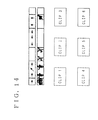
- an operating screen of a motion picture editing device that was developed by a group including the present inventor will be described.
- an operating button 21 for fetching digital images from a file
- an operating button 22 for fetching images from a digital video camera
- a pre-edited index display 23 for displaying indexes for pre-edited clips
- a bar 24, for displaying relationships between individual clips and a motion picture
- a post-edited index display 25 for displaying an index for a clip, the scene of which has been selected by an editor.
- the editor selects clips to be edited from the indexes that are displayed on the pre-edited index display 23, while referring to the display on the bar 24, the indexes for the selected clips are displayed on the post-edited index display 25, and the clips are linked in the order at which they were selected.
- the editing device is described in detail in another patent application.
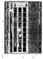
- the display on the pre-edited index display 23 is linked with the display on the bar 24 so that the editor can easily ascertain the contents of the clips.
- various colors corresponding to the indexes for the clips on the pre-edited index display 23 are used to establish the lengths of the individual dips that are displayed on the bar 24. Therefore, the ratio of the length of each dip to the motion picture and the location of each dip in the motion picture can be ascertained at a glance.
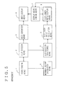
- the display device for providing such a display comprises, as is shown in Fig. 3, video reading means 1, for reading digital images from a video camera or from a hard disk; clip division means 2, for dividing a digital image into clips; clip division storage means 4, for holding IN point and OUT point data for the clips; index generation means 3, for generating indexes for the clips; index display means 6, for displaying the indexes generated by the index generation means 3; clip length ratio calculation means 5, for calculating a ratio for the length of each clip; clip length ratio display means 8, for displaying on the bar 24 separate segments whose sizes correspond to the length ratio for individual clips; and display means linking means 7, for, linking the indexes displayed on the index display means 6 with the separate segments on the bar 24.
- the video reading means 1 of the display device reads from a storage device, such as a hard disk, a video signal that is encoded using the DV method and transmits the encoded signal to the clip division means 2.
- the DV method is based on the specifications for digital video devices, such as digital video cameras, and conforms to the video cassette recorder specifications that were established in 1996, "Specifications for Consumer-Use Digital VCRs (HD Digital VCR Conference, 1996).”
- DCT disersion cosine conversion
- One macro block for DV data consists of four horizontally arranged luminance signal blocks and two chrominance signal (CR and CB) blocks that are located at corresponding positions, and has a color component form of 4:1:1.
- a super block is constituted by 27 of the macro blocks, and a 5 x 10 array of the super blocks constitutes one frame.
- the clip division means 2 When the clip division means 2 receives a video signal, it generates clips using a method selected by an operator, i.e., a method for dividing an image at specific time intervals (e.g., intervals of one second) or an image division method for automatically detecting a change of scene.
- a method selected by an operator i.e., a method for dividing an image at specific time intervals (e.g., intervals of one second) or an image division method for automatically detecting a change of scene.
- a differential value between the video data for two sequentially positioned frames is calculated (for DV data, the compression rate for each macro block is employed as the video data for the calculation, and the sum of the differential values between frames is acquired).
- the differential value is greater than a threshold value, it is determined that at that position there has been a change of scene.
- the index generation means 3 generates an index using the first ' frame of a clip obtained by the clip division means 2.
- a Bitmap that is so generated by extracting a direct current element is regarded as an index.
- the index display means 6 displays in order the Bitmaps generated along the time axis by the index generation means 3.
- the clip division data storage means 4 stores IN point and OUT point data for the clips provided by the clip division means 2, and the clip length ratio calculation means 5 employs the IN point and OUT point data for clip division to calculate the ratio of the length of each clip to the overall length of the motion picture.
- the clip length ratio display means 8 employs the length ratios obtained by the clip length ratio calculation means 5 to divide the area of the bar 24, so that the ratio of the length of each clip to the total length of a motion picture is readily apparent.
- the display means linking means 7 links the indexes displayed by the index display means 6 with the segments on the bar 24 displayed by the clip length ratio display means 8. For example, an "x" is displayed in the segment on the bar 24 that corresponds to the index for clip x, or n colors are assigned in order to the clips and a color corresponding to a clip is assigned to a corresponding segment on the bar 24.
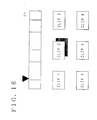
- the area of a bar 24 is divided into segments using the ratios of the lengths of individual clips to the overall length of a motion picture, and the movement of an image for a clip is displayed by using arrows in a corresponding segment.
- a display device for providing such a display comprises, as is shown in Fig. 5, motion vector calculation means 9, for determining the movement of an object from an image that is read.
- the other arrangements are the same as those for the device of the first embodiment in Fig. 3.
- the motion vector calculation means 9 extracts two sequential frames from the video reading means 1 at a constant time interval (e.g., an interval of two seconds), and calculates a motion vector for predetermined segments (e.g., centers) of frames.
- the calculation performed for the motion vector is the same as that performed for Mpegl and 2.
- the motion vector calculation means 9 obtains the motion vector, it converts the vector into one that most nearly approximates one of a number of vectors for n directions (e.g., four directions). When no motion vector is obtained, it is assumed that no vector exists.
- the display means linking means 7 employs the vector obtained by the motion vector calculation means 9 to perform the mapping of the bar 24 that is displayed by the clip length ratio display means 8.
- the arrows that represent motion vectors for the images of the individual clips are displayed on the bar 24.
- a plurality of arrows are displayed that represent the motion vectors at constant time intervals.
- the area of a bar 24 is divided into segments at ratios corresponding to the lengths of individual clips to the overall length of a motion picture, and a main color used in an image for a clip and the changing of the color are displayed in a corresponding segment.
- the scene for a clip represents the sunset
- the color displayed in a corresponding segment on the bar 24 is changed to a darker color.
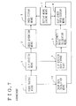
- a display device for providing such a display comprises, as is shown in Fig. 4, color data acquisition means 10 for acquiring color data from an image that is read.
- the other arrangements are the same as those for the device of the first embodiment shown in Fig. 3.
- the color data acquisition means 10 acquires a single frame from the video reading means 1 at constant time intervals, and employs luminance and chrominance signals to acquire, for each block, color data that are included in the frame. Then, the color data for each block is changed to one that most nearly approximates one color of a set of n colors. The color of the set of n colors that is most used in the frame is determined and is employed as the model color for the frame. While in this embodiment only one color is used as the model color for a frame, a frame may be divided into a plurality (m) of regions, a model color for each of the regions may be determined, and the so obtained m colors may be employed as model colors for the frame.
- the display means linking means 7 employs the model color obtained by the color data calculation means 10 to perform the mapping for the bar 24 that is displayed by the clip length ratio display means 8.
- the model colors for images in the individual clips are displayed on the bar 24.
- the model colors are displayed in order at constant time intervals.
- the area of a bar 24 is divided into segments at ratios of the lengths of individual clips to the overall length of a motion picture, and the thickness of a border line that is displayed corresponds to the degree of change between scenes.
- a thick border line is displayed.
- a thin border line is , displayed.
- a display device for providing such a display comprises, as is shown in Fig. 9, differential value storage means 11 for holding the differential value calculated by the clip division means 2 for the detection of scenes.
- the other arrangements are the same as those for the device of the first embodiment shown in Fig. 3.
- the clip division means 2 when the clip division means 2 detects scene changes in images carried by a video signal and divides the images into segments, the differential values between the frames that are calculated for the clip division by the clip division means 2 are stored in the difference value storage means 11.
- the clip division means 2 divides the images at constant time intervals, for each division point it calculates a differential value between the preceding and the succeeding frame and stores it in the differential value storage means 11.
- the display means linking means 7 employs the differential value data stored in the differential value storage means 11 to sort into n groups the image separation types for the clips, and transmits a message to that effect to the clip length ratio display means 8. Based on the received data, the clip length ratio display means 8 displays the bar 24, while changing the thicknesses of the border lines on the bar 24.
- border lines having widths that correspond to the degree of the changes between scenes are displayed in the bar 24.
- the clip length ratio display means 8 may change the types of border lines that are used (broken lines or wavy lines) or the colors of the border lines,
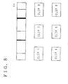
- the area of the bar 24 is divided into segments at ratios of the lengths of individual clips to the overall length of a motion picture, and the object that moves the most is extracted for each clip and is displayed in a corresponding segment.
- two planes are displayed in a segment on the bar 24, it means that the planes are moving in the index for a corresponding clip and that the moving planes also appear in an image after a specific time has elapsed.
- a horse is displayed only on the right side of a segment on the bar 24, it means that no moving object is shown in the index, but that a moving horse appears in an image after a predetermined time has elapsed.
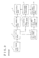
- a display device for providing such a display comprises, as is shown in Fig. 11, maximum movement object extraction means 12 for detecting, from images that is read, the object that has the maximum movement.
- maximum movement object extraction means 12 for detecting, from images that is read, the object that has the maximum movement.
- the maximum movement object extraction means 12 extracts two sequential frames from the video reading means 1 at a constant time interval, calculates a motion vector for each macro block, and cuts out an image portion that reflects the maximum motion vector and that moves in the same way.
- the display means linking means 7 performs mapping, on the bar displayed by the clip length ratio display means 8, for an image that is extracted by the maximum movement object extraction means 12.
- an object that moves the most in an image is displayed on the bar 24.
- a plurality of objects that move the most are selected from among the images extracted at constant time intervals along the time axis and are displayed.
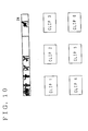
- the area of the bar 24 is divided into segments at ratios of the lengths of individual clips to the overall length of a motion picture.
- the sound recorded with images for a clip is a voice
- the figure of a person is displayed in a segment
- the sound recorded with images is music
- a note is displayed.
- both voice and music are recorded, the figure of a person and a note are overlapped on a display.
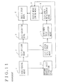
- a display device for providing such a display comprises, as is shown in Fig. 13, sound data acquisition means 13 for acquiring sounds recorded with images and identifying types of the sounds.
- the other arrangements are the same as those of the device for the first embodiment in Fig. 3.
- the sound data acquisition means 13 extracts sound data, which have been recorded with images, from the video reading means 1 at constant time intervals, and examines the frequency bands for sounds and the management of changes in the frequencies, and the presence/absence of a soundless portion to identify whether the sound is a voice or is music (the voice of a person includes an invoiced portion, while music does not include such a portion).
- the display means linking means 7 transmits the sound data obtained by the sound data acquisition means 13 to the clip length ratio display means 8, which, based on the sound data, displays the figure of a person, or a note, in each segment on the bar 24.
- the figures of persons or notes are displayed to represent the sound type, and for a clip for which the ratio of its length to the overall length of a motion picture is large, a plurality of sound types are displayed that are identified at constant time intervals along the time axis.
- a display method according to a seventh embodiment can be provided by the arbitrary combination of the display methods of the second to the sixth embodiments.
- Fig. 14 is shown a combination of the display methods of the second and the fifth embodiments. With this display, an object in the index that is moving and the direction of its movement can be ascertained.
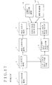
- a display device for providing such a display comprises, as is shown in Fig. 15, a means unit 14 that includes motion vector calculation means, color data calculation means, differential value storage means, maximum movement object extraction means and sound data acquisition means; and display data selection means 15 for selecting several means from the means unit 14.
- the other arrangements are the same as those for the device according to the first embodiment in Fig. 3.
- the selected means is activated to perform a display method selected from those of the second to the sixth embodiments.
- the area of a bar 24 is divided into segments at ratios of the lengths of individual clips to the overall length of a motion picture.
- a triangular mark is displayed in a corresponding segment on the bar 24.
- a mark is displayed in the index of a corresponding clip. Therefore, the editor can immediately understand the correspondence between the clips and the segments on the bar 24, and can quickly find a specific clip by designating an approximate location of the motion picture on the bar 24.
- a display device for providing such a display comprises, as is shown in Fig. 17, segment selection means 16 for permitting an editor to select a segment, and marking means 17 for providing a mark at a selected segment and at its linking destination.
- segment selection means 16 for permitting an editor to select a segment
- marking means 17 for providing a mark at a selected segment and at its linking destination.
- the marking means 17 designates a mark figure that is to be provided for a selected index, and a mark figure that is to be provided for a linking position in the bar 24.
- the display means linking means 7 transmits to the index display means 6 data that indicate the selected index and the mark figure that is to be provided for the index, and also transmits to the clip length ratio display means 8 the position of the bar 24 for linking with the selected index and the mark figure that is to be provided for that position.
- the clip length ratio display means 8 Upon receipt of the data, the clip length ratio display means 8 displays a triangular mark at the selected position on the bar 24, and the index display means 6 displays a shadow mark at the selected index.
- the position of each clip relative to a motion picture, and the ratio of the length of each clip to the overall length of the motion picture can be visually identified.
- the display method for displaying a motion vector the movement of a typical image for a clip is ascertained; according to the display method for displaying a change in colors, the change in the image color for a clip is ascertained; and according to the display method for changing the shape of border lines in consonance with the differential value between the images, the magnitude of the change between scenes is ascertained from the thickness and the type of border line. And according to the display method for displaying an object that performs the maximum move, what is moving in a typical image is ascertained, and according to the display method for displaying a sound type, the types of sounds recorded with images is ascertained.
- an editor can exactly recall the contents of the individual clips of a motion picture the editor took, or of a motion picture that the editor previewed, and can precisely and efficiently perform editing.
- the display method whereby when a typical image is selected, a mark is displayed on a figure that represents the overall length of a motion picture and whereby when a specific position is selected in a figure, a corresponding typical image is displayed so that an editor can identify it, the correspondence between the area of the graphic representation that represents the overall length of a moving image and the clip that is represented by a typical image can be understood at a glance. Further, when an approximate position in the motion picture is selected by referring to the figure, a pertinent clip can be found.
- the clip display device of the present invention can perform these clip display methods.
- the display device that can perform a combination of these clip display methods, when a plurality of display methods are performed, the contents of a clip can be understood better, and the efficiency of the editing can be further improved.
Applications Claiming Priority (3)
| Application Number | Priority Date | Filing Date | Title |
|---|---|---|---|
| JP277996/97 | 1997-09-26 | ||
| JP27799697 | 1997-09-26 | ||
| JP9277996A JPH11103441A (ja) | 1997-09-26 | 1997-09-26 | クリップ表示方法とその表示装置 |
Publications (2)
| Publication Number | Publication Date |
|---|---|
| EP0907147A2 true EP0907147A2 (fr) | 1999-04-07 |
| EP0907147A3 EP0907147A3 (fr) | 2000-04-26 |
Family
ID=17591182
Family Applications (1)
| Application Number | Title | Priority Date | Filing Date |
|---|---|---|---|
| EP98307789A Withdrawn EP0907147A3 (fr) | 1997-09-26 | 1998-09-25 | Procédé d'affichage de séquences vidéo et dispositif d'affichage |
Country Status (4)
| Country | Link |
|---|---|
| US (1) | US6310625B1 (fr) |
| EP (1) | EP0907147A3 (fr) |
| JP (1) | JPH11103441A (fr) |
| CN (1) | CN1228727C (fr) |
Cited By (6)
| Publication number | Priority date | Publication date | Assignee | Title |
|---|---|---|---|---|
| WO2000045596A1 (fr) * | 1999-01-29 | 2000-08-03 | Sony Corporation | Procede de description de donnees et unite de traitement de donnees |
| WO2000048397A1 (fr) * | 1999-02-15 | 2000-08-17 | Sony Corporation | Procede de traitement de signal et dispositif de traitement video/audio |
| WO2001003005A1 (fr) * | 1999-06-30 | 2001-01-11 | Sharp Kabushiki Kaisha | Appareil d'enregistrement d'informations de recherche d'images dynamiques et dispositif de recherche d'images dynamiques |
| EP1630811A1 (fr) * | 2004-08-24 | 2006-03-01 | Magix AG | Système et méthode pour la création automatique de contenu haute définition dépendant de l'appareil d'affichage |
| EP1909195A1 (fr) * | 2006-10-05 | 2008-04-09 | Kubj Limited | Divers procédés et appareil pour le déplacement de vignettes avec des métadonnées |
| US8078603B1 (en) | 2006-10-05 | 2011-12-13 | Blinkx Uk Ltd | Various methods and apparatuses for moving thumbnails |
Families Citing this family (22)
| Publication number | Priority date | Publication date | Assignee | Title |
|---|---|---|---|---|
| US20020057294A1 (en) * | 1996-12-06 | 2002-05-16 | Satoshi Ejima | Information processing apparatus |
| US20060020894A1 (en) * | 1996-12-06 | 2006-01-26 | Nikon Corporation | Information processing apparatus |
| EP1033718B1 (fr) * | 1999-03-02 | 2006-01-11 | Hitachi Denshi Kabushiki Kaisha | Méthode et appareil pour afficher une information d'images animées |
| US7020351B1 (en) * | 1999-10-08 | 2006-03-28 | Sarnoff Corporation | Method and apparatus for enhancing and indexing video and audio signals |
| WO2001028238A2 (fr) * | 1999-10-08 | 2001-04-19 | Sarnoff Corporation | Procede et appareil permettant d'ameliorer et d'indexer des signaux video et audio |
| WO2001056281A1 (fr) | 2000-01-26 | 2001-08-02 | Sony Corporation | Procede et systeme informatique et support d'enregistrement de programmes |
| JP4682434B2 (ja) * | 2000-04-21 | 2011-05-11 | ソニー株式会社 | 情報処理装置および方法、記録媒体、並びにプログラム |
| EP2546833A3 (fr) * | 2000-04-21 | 2014-08-20 | Sony Corporation | Appareil, procédé et logiciel de traitement d'informations |
| JP4683253B2 (ja) * | 2000-07-14 | 2011-05-18 | ソニー株式会社 | Av信号処理装置および方法、プログラム、並びに記録媒体 |
| US6774908B2 (en) * | 2000-10-03 | 2004-08-10 | Creative Frontier Inc. | System and method for tracking an object in a video and linking information thereto |
| JP2004295568A (ja) * | 2003-03-27 | 2004-10-21 | Sony Corp | 情報処理装置、および情報処理方法、並びにコンピュータ・プログラム |
| US7471871B2 (en) * | 2003-08-25 | 2008-12-30 | Hewlett-Packard Development Company, L.P. | Index validation system and method |
| JP4385974B2 (ja) * | 2004-05-13 | 2009-12-16 | ソニー株式会社 | 画像表示方法、画像処理装置、プログラム及び記録媒体 |
| JP2006165824A (ja) * | 2004-12-03 | 2006-06-22 | Fuji Xerox Co Ltd | 画像表示プログラム、画像表示方法及び画像表示装置 |
| US20070162857A1 (en) * | 2006-01-06 | 2007-07-12 | Ralf Weber | Automated multimedia authoring |
| US20070162855A1 (en) * | 2006-01-06 | 2007-07-12 | Kelly Hawk | Movie authoring |
| US7636889B2 (en) * | 2006-01-06 | 2009-12-22 | Apple Inc. | Controlling behavior of elements in a display environment |
| JP2007208874A (ja) * | 2006-02-06 | 2007-08-16 | Nec Electronics Corp | 変化点検出装置及び変化点検出方法、並びに記録装置及び記録再生装置 |
| JP4856105B2 (ja) * | 2008-01-31 | 2012-01-18 | 株式会社東芝 | 電子機器および表示処理方法 |
| JP2009055618A (ja) * | 2008-09-25 | 2009-03-12 | Casio Comput Co Ltd | 電子カメラ、及び電子カメラの制御プログラム |
| US20110280476A1 (en) * | 2010-05-13 | 2011-11-17 | Kelly Berger | System and method for automatically laying out photos and coloring design elements within a photo story |
| CN111311477B (zh) * | 2020-02-28 | 2024-05-07 | 深圳看到科技有限公司 | 图像编辑方法、装置及对应的存储介质 |
Citations (3)
| Publication number | Priority date | Publication date | Assignee | Title |
|---|---|---|---|---|
| US5177513A (en) * | 1991-07-19 | 1993-01-05 | Kabushiki Kaisha Toshiba | Moving picture managing device and method of managing a moving picture |
| EP0660249A1 (fr) * | 1993-12-27 | 1995-06-28 | AT&T Corp. | Système d'indexation de tables des matières |
| US5521841A (en) * | 1994-03-31 | 1996-05-28 | Siemens Corporate Research, Inc. | Browsing contents of a given video sequence |
Family Cites Families (3)
| Publication number | Priority date | Publication date | Assignee | Title |
|---|---|---|---|---|
| US5953485A (en) * | 1992-02-07 | 1999-09-14 | Abecassis; Max | Method and system for maintaining audio during video control |
| US5442744A (en) * | 1992-04-03 | 1995-08-15 | Sun Microsystems, Inc. | Methods and apparatus for displaying and editing multimedia information |
| JP3308061B2 (ja) | 1993-09-08 | 2002-07-29 | 株式会社日立製作所 | ラベル作成方法、ラベル作成プログラムを記録した記録媒体、およびラベル作成装置 |
-
1997
- 1997-09-26 JP JP9277996A patent/JPH11103441A/ja active Pending
-
1998
- 1998-09-25 US US09/160,545 patent/US6310625B1/en not_active Expired - Lifetime
- 1998-09-25 EP EP98307789A patent/EP0907147A3/fr not_active Withdrawn
- 1998-09-28 CN CNB981194486A patent/CN1228727C/zh not_active Expired - Fee Related
Patent Citations (3)
| Publication number | Priority date | Publication date | Assignee | Title |
|---|---|---|---|---|
| US5177513A (en) * | 1991-07-19 | 1993-01-05 | Kabushiki Kaisha Toshiba | Moving picture managing device and method of managing a moving picture |
| EP0660249A1 (fr) * | 1993-12-27 | 1995-06-28 | AT&T Corp. | Système d'indexation de tables des matières |
| US5521841A (en) * | 1994-03-31 | 1996-05-28 | Siemens Corporate Research, Inc. | Browsing contents of a given video sequence |
Non-Patent Citations (10)
| Title |
|---|
| AKUTSU A ET AL: "VIDEO INDEXING USING MOTION VECTORS" PROCEEDINGS OF THE SPIE,US,SPIE, BELLINGHAM, VA, vol. 1818, no. PART 03, 18 November 1992 (1992-11-18), pages 1522-1530, XP000671350 * |
| AKUTSU A ET AL: "VIDEO INTERFACE FOR SPATIOTEMPORAL INTERACTIONS BASED ON MULTI-DIMENSIONAL VIDEO COMPUTING" IEEE INTERNATIONAL CONFERENCE ON ACOUSTICS, SPEECH, AND SIGNAL PROCESSING (ICASSP),US,LOS ALIMITOS,CA: IEEE COMP. SOC. PRESS,1997, pages 191-194, XP000789152 ISBN: 0-8186-7920-4 * |
| COURTNEY J D: "AUTOMATIC VIDEO INDEXING VIA OBJECT MOTION ANALYSIS" PATTERN RECOGNITION,US,PERGAMON PRESS INC. ELMSFORD, N.Y, vol. 30, no. 4, 1 April 1997 (1997-04-01), pages 607-625, XP000690822 ISSN: 0031-3203 * |
| DIMITROVA N ET AL: "CONTENT-BASED VIDEO RETRIEVAL BY EXAMPLE VIDEO CLIP" PROCEEDINGS OF SPIE,US,BELLINGHAM, SPIE, vol. 3022, 1997, pages 59-70, XP000742371 ISBN: 0-8194-2433-1 * |
| GUENSEL B ET AL: "OBJECT-BASED VIDEO INDEXING FOR VIRTUAL STUDIO PRODUCTIONS" PROCEEDINGS OF THE IEEE COMPUTER SOCIETY CONFERENCE ON COMPUTER VISION AND PATTERN RECOGNITION,US,LOS ALAMITOS, IEEE COMP. SOC. PRESS, vol. CONF. 16, 1997, pages 769-774, XP000776575 ISBN: 0-7803-4236-4 * |
| HIROTADA UEDA ET AL: "AUTOMATIC STRUCTURE VISUALIZATION FOR VIDEO EDITING" PROCEEDINGS OF THE CONFERENCE ON HUMAN FACTORS IN COMPUTING SYSTEMS. (INTERCHI),US,READING, ADDISON WESLEY, vol. -, 1993, pages 137-141, XP000570441 * |
| TONOMURA Y ET AL: "CONTENT ORIENTED VISUAL INTERFACE USING VIDEO ICONS FOR VISUAL DATABASE SYSTEMS" JOURNAL OF VISUAL LANGUAGES AND COMPUTING,GB,LONDON, vol. 1, 1 January 1990 (1990-01-01), pages 183-198, XP000195706 * |
| UEDA ET AL: "Automatic structure visualization for video editing" PROCEEDINGS OF THE CONFERENCE ON HUMAN FACTORS IN COMPUTING SYSTEMS, 1993, pages 545-546, US, READING, ADDISON WESLEY * |
| UEDA H ET AL: "IMPACT: AN INTERACTIVE NATURAL-MOTION-PICTURE DEDICATED MULTIMEDIA AUTHORING SYSTEM" HUMAN FACTORS IN COMPUTING SYSTEMS CONFERENCE PROCEEDINGS,1991, XP000856890 * |
| YOSHINOBU TONOMURA ET AL: "STRUCTURED VIDEO COMPUTING" IEEE MULTIMEDIA,US,IEEE COMPUTER SOCIETY, vol. 1, no. 3, 21 September 1994 (1994-09-21), pages 34-43, XP000476887 ISSN: 1070-986X * |
Cited By (11)
| Publication number | Priority date | Publication date | Assignee | Title |
|---|---|---|---|---|
| WO2000045596A1 (fr) * | 1999-01-29 | 2000-08-03 | Sony Corporation | Procede de description de donnees et unite de traitement de donnees |
| US6996171B1 (en) | 1999-01-29 | 2006-02-07 | Sony Corporation | Data describing method and data processor |
| WO2000048397A1 (fr) * | 1999-02-15 | 2000-08-17 | Sony Corporation | Procede de traitement de signal et dispositif de traitement video/audio |
| US6710822B1 (en) | 1999-02-15 | 2004-03-23 | Sony Corporation | Signal processing method and image-voice processing apparatus for measuring similarities between signals |
| WO2001003005A1 (fr) * | 1999-06-30 | 2001-01-11 | Sharp Kabushiki Kaisha | Appareil d'enregistrement d'informations de recherche d'images dynamiques et dispositif de recherche d'images dynamiques |
| US7092040B1 (en) | 1999-06-30 | 2006-08-15 | Sharp Kabushiki Kaisha | Dynamic image search information recording apparatus and dynamic image searching device |
| US7884884B2 (en) | 1999-06-30 | 2011-02-08 | Sharp Kabushiki Kaisha | Dynamic image search information recording apparatus and dynamic image searching devices |
| EP1630811A1 (fr) * | 2004-08-24 | 2006-03-01 | Magix AG | Système et méthode pour la création automatique de contenu haute définition dépendant de l'appareil d'affichage |
| EP1909195A1 (fr) * | 2006-10-05 | 2008-04-09 | Kubj Limited | Divers procédés et appareil pour le déplacement de vignettes avec des métadonnées |
| US8078603B1 (en) | 2006-10-05 | 2011-12-13 | Blinkx Uk Ltd | Various methods and apparatuses for moving thumbnails |
| US8196045B2 (en) | 2006-10-05 | 2012-06-05 | Blinkx Uk Limited | Various methods and apparatus for moving thumbnails with metadata |
Also Published As
| Publication number | Publication date |
|---|---|
| US6310625B1 (en) | 2001-10-30 |
| JPH11103441A (ja) | 1999-04-13 |
| CN1228727C (zh) | 2005-11-23 |
| CN1219822A (zh) | 1999-06-16 |
| EP0907147A3 (fr) | 2000-04-26 |
Similar Documents
| Publication | Publication Date | Title |
|---|---|---|
| US6310625B1 (en) | Clip display method and display device therefor | |
| JP3432348B2 (ja) | 代表画像表示方法、代表画像表示装置およびこの装置を用いた動画検索装置 | |
| US6930687B2 (en) | Method of displaying a digital image | |
| US6392710B1 (en) | Graphical user interface for field-based definition of special effects in a video editing system | |
| Tonomura et al. | Structured video computing | |
| US7110592B2 (en) | Image recording apparatus, image reproducing apparatus and methods therefor | |
| EP0917148A3 (fr) | Un appareil pour éditer une image animée avec des informations associées, un procédé d'édition et milieu d'enregistrement pour stocker des procedures selon le même procédé | |
| CN109936763A (zh) | 视频的处理及发布方法 | |
| GB2258117A (en) | Interactive video image browser | |
| JPH08163488A (ja) | 動画像ダイジェスト生成方法及び動画像ダイジェスト生成装置 | |
| JPH0738842A (ja) | 動画編集装置 | |
| JP2000350156A (ja) | 動画像情報の記憶方法及びこれを記録した記録媒体 | |
| EP1738365B1 (fr) | Zoom horizontal d'images du pouce permettant une navigation efficace lors de l'edition de videos longues. | |
| JP4154012B2 (ja) | 画像表示方法を実現するためのプログラムを記録した記録媒体及び画像合成装置 | |
| EP1221660A2 (fr) | Rejouer des informations vidéo | |
| Kim et al. | Visual rhythm and shot verification | |
| JP3791869B2 (ja) | 画像編集方法及び画像編集装置並びにコンピュータに画像編集処理動作を実行させるためのプログラムを記録した媒体 | |
| JP3534592B2 (ja) | 代表画像生成装置 | |
| JPH08115250A (ja) | ハイパーメディアシステム | |
| JP2006101076A (ja) | 動画編集方法、動画編集装置及びプログラム | |
| JP3558886B2 (ja) | 映像処理装置 | |
| JP2000125243A (ja) | 映像記録再生装置及び記録媒体 | |
| JP2003283968A (ja) | 動画像内容表示装置 | |
| JP3426997B2 (ja) | 被写体情報取得機能付き編集用映像撮影方法及び装置並びに該方法を記述したプログラムを記録した記憶媒体 | |
| WO2009024966A2 (fr) | Procédé pour adapter des médias à une visualisation sur petits écrans d'affichage |
Legal Events
| Date | Code | Title | Description |
|---|---|---|---|
| PUAI | Public reference made under article 153(3) epc to a published international application that has entered the european phase |
Free format text: ORIGINAL CODE: 0009012 |
|
| 17P | Request for examination filed |
Effective date: 19981021 |
|
| AK | Designated contracting states |
Kind code of ref document: A2 Designated state(s): DE FR GB |
|
| AX | Request for extension of the european patent |
Free format text: AL;LT;LV;MK;RO;SI |
|
| PUAL | Search report despatched |
Free format text: ORIGINAL CODE: 0009013 |
|
| AK | Designated contracting states |
Kind code of ref document: A3 Designated state(s): AT BE CH CY DE DK ES FI FR GB GR IE IT LI LU MC NL PT SE |
|
| AX | Request for extension of the european patent |
Free format text: AL;LT;LV;MK;RO;SI |
|
| RIC1 | Information provided on ipc code assigned before grant |
Free format text: 7G 06T 11/60 A, 7G 06F 17/30 B |
|
| AKX | Designation fees paid |
Free format text: DE FR GB |
|
| 17Q | First examination report despatched |
Effective date: 20030129 |
|
| GRAP | Despatch of communication of intention to grant a patent |
Free format text: ORIGINAL CODE: EPIDOSNIGR1 |
|
| RIC1 | Information provided on ipc code assigned before grant |
Ipc: G11B 27/34 20060101ALI20060317BHEP Ipc: G06F 17/30 20060101ALI20060317BHEP Ipc: G06T 11/60 20060101AFI20060317BHEP |
|
| STAA | Information on the status of an ep patent application or granted ep patent |
Free format text: STATUS: THE APPLICATION IS DEEMED TO BE WITHDRAWN |
|
| 18D | Application deemed to be withdrawn |
Effective date: 20060808 |