EP0907074B1 - Optical chemical sensor - Google Patents
Optical chemical sensor Download PDFInfo
- Publication number
- EP0907074B1 EP0907074B1 EP98890284A EP98890284A EP0907074B1 EP 0907074 B1 EP0907074 B1 EP 0907074B1 EP 98890284 A EP98890284 A EP 98890284A EP 98890284 A EP98890284 A EP 98890284A EP 0907074 B1 EP0907074 B1 EP 0907074B1
- Authority
- EP
- European Patent Office
- Prior art keywords
- optical sensor
- sensor according
- luminescence
- oxygen
- matrix
- Prior art date
- Legal status (The legal status is an assumption and is not a legal conclusion. Google has not performed a legal analysis and makes no representation as to the accuracy of the status listed.)
- Expired - Lifetime
Links
Images


Classifications
-
- G—PHYSICS
- G01—MEASURING; TESTING
- G01N—INVESTIGATING OR ANALYSING MATERIALS BY DETERMINING THEIR CHEMICAL OR PHYSICAL PROPERTIES
- G01N21/00—Investigating or analysing materials by the use of optical means, i.e. using sub-millimetre waves, infrared, visible or ultraviolet light
- G01N21/62—Systems in which the material investigated is excited whereby it emits light or causes a change in wavelength of the incident light
- G01N21/63—Systems in which the material investigated is excited whereby it emits light or causes a change in wavelength of the incident light optically excited
- G01N21/64—Fluorescence; Phosphorescence
- G01N21/6408—Fluorescence; Phosphorescence with measurement of decay time, time resolved fluorescence
-
- G—PHYSICS
- G01—MEASURING; TESTING
- G01N—INVESTIGATING OR ANALYSING MATERIALS BY DETERMINING THEIR CHEMICAL OR PHYSICAL PROPERTIES
- G01N21/00—Investigating or analysing materials by the use of optical means, i.e. using sub-millimetre waves, infrared, visible or ultraviolet light
- G01N21/62—Systems in which the material investigated is excited whereby it emits light or causes a change in wavelength of the incident light
- G01N21/63—Systems in which the material investigated is excited whereby it emits light or causes a change in wavelength of the incident light optically excited
- G01N21/64—Fluorescence; Phosphorescence
- G01N21/6428—Measuring fluorescence of fluorescent products of reactions or of fluorochrome labelled reactive substances, e.g. measuring quenching effects, using measuring "optrodes"
- G01N2021/6432—Quenching
-
- G—PHYSICS
- G01—MEASURING; TESTING
- G01N—INVESTIGATING OR ANALYSING MATERIALS BY DETERMINING THEIR CHEMICAL OR PHYSICAL PROPERTIES
- G01N21/00—Investigating or analysing materials by the use of optical means, i.e. using sub-millimetre waves, infrared, visible or ultraviolet light
- G01N21/62—Systems in which the material investigated is excited whereby it emits light or causes a change in wavelength of the incident light
- G01N21/63—Systems in which the material investigated is excited whereby it emits light or causes a change in wavelength of the incident light optically excited
- G01N21/64—Fluorescence; Phosphorescence
- G01N21/6428—Measuring fluorescence of fluorescent products of reactions or of fluorochrome labelled reactive substances, e.g. measuring quenching effects, using measuring "optrodes"
- G01N2021/6434—Optrodes
-
- G—PHYSICS
- G01—MEASURING; TESTING
- G01N—INVESTIGATING OR ANALYSING MATERIALS BY DETERMINING THEIR CHEMICAL OR PHYSICAL PROPERTIES
- G01N21/00—Investigating or analysing materials by the use of optical means, i.e. using sub-millimetre waves, infrared, visible or ultraviolet light
- G01N21/75—Systems in which material is subjected to a chemical reaction, the progress or the result of the reaction being investigated
- G01N21/77—Systems in which material is subjected to a chemical reaction, the progress or the result of the reaction being investigated by observing the effect on a chemical indicator
- G01N21/7703—Systems in which material is subjected to a chemical reaction, the progress or the result of the reaction being investigated by observing the effect on a chemical indicator using reagent-clad optical fibres or optical waveguides
- G01N2021/7706—Reagent provision
- G01N2021/773—Porous polymer jacket; Polymer matrix with indicator
-
- G—PHYSICS
- G01—MEASURING; TESTING
- G01N—INVESTIGATING OR ANALYSING MATERIALS BY DETERMINING THEIR CHEMICAL OR PHYSICAL PROPERTIES
- G01N21/00—Investigating or analysing materials by the use of optical means, i.e. using sub-millimetre waves, infrared, visible or ultraviolet light
- G01N21/75—Systems in which material is subjected to a chemical reaction, the progress or the result of the reaction being investigated
- G01N21/77—Systems in which material is subjected to a chemical reaction, the progress or the result of the reaction being investigated by observing the effect on a chemical indicator
- G01N2021/7756—Sensor type
- G01N2021/7763—Sample through flow
-
- G—PHYSICS
- G01—MEASURING; TESTING
- G01N—INVESTIGATING OR ANALYSING MATERIALS BY DETERMINING THEIR CHEMICAL OR PHYSICAL PROPERTIES
- G01N21/00—Investigating or analysing materials by the use of optical means, i.e. using sub-millimetre waves, infrared, visible or ultraviolet light
- G01N21/75—Systems in which material is subjected to a chemical reaction, the progress or the result of the reaction being investigated
- G01N21/77—Systems in which material is subjected to a chemical reaction, the progress or the result of the reaction being investigated by observing the effect on a chemical indicator
- G01N2021/7769—Measurement method of reaction-produced change in sensor
- G01N2021/7786—Fluorescence
-
- Y—GENERAL TAGGING OF NEW TECHNOLOGICAL DEVELOPMENTS; GENERAL TAGGING OF CROSS-SECTIONAL TECHNOLOGIES SPANNING OVER SEVERAL SECTIONS OF THE IPC; TECHNICAL SUBJECTS COVERED BY FORMER USPC CROSS-REFERENCE ART COLLECTIONS [XRACs] AND DIGESTS
- Y10—TECHNICAL SUBJECTS COVERED BY FORMER USPC
- Y10T—TECHNICAL SUBJECTS COVERED BY FORMER US CLASSIFICATION
- Y10T436/00—Chemistry: analytical and immunological testing
- Y10T436/20—Oxygen containing
- Y10T436/207497—Molecular oxygen
Definitions
- the invention relates to an optical chemical sensor with a matrix which has a luminescence indicator whose luminescence can be quenched or quenched with oxygen.
- optical sensors hereinafter referred to simply as “optical sensors” or “sensors”, are now widely used, preferably in the form of membranes, in sensor configurations to detect certain substances, such as oxygen or glucose, in a sample
- Optical sensors are used, for example, in environmental measurement technology and in emergency medicine (blood gas analysis)
- the operation of optical sensors and the basic structure of a sensor configuration which generally comprises a multilayer optical sensor, an excitation light source and an optoelectronic detection system , is described in the literature (eg Sensors and Actuators B 11 (1993), pp. 281-289, Sensors and Actuators B 29 (1995), pp. 169-173).
- Lübbers US Pat. No. RE 31,879 describes a luminescence-optical oxygen sensor with the indicator pyrenebutyric acid, optionally stirred into a high-permeability oxygen-permeable silicon matrix whose sensitive layer is between a light-permeable cover layer and an oxygen-permeable base layer which is in contact with the fluid under investigation. is installed.
- Marsoner describes an oxygen sensor with modified dyes which are readily soluble in silicone and thus offer increased stability of the sensor against aggregation of the dye molecules.
- the sensor is going through Stir the dye into a prepolymer and then polymerize to silicone.
- US-A-5,242,835 to Jensen discloses a method of increasing the concentration of oxygen in a sample by detecting the emission of the singlet oxygen itself excited by energy transfer upon quenching of the luminescence, which occurs at about a wavelength of 1270 nm determine.
- This method is also susceptible to photo-decomposition of indicator or matrix by just this reactive singlet oxygen, since the latter in a photochemical reaction falls back radiationless in the ground state and also the sensitizer molecules (indicators), which are used for the production of singlet oxygen, attacked become.
- optical chemical sensors generally contain dyes which react to a change in concentration of the substance to be analyzed within the sensitive layer with a change in their photophysical properties. For example, luminescence intensity and decay time of oxygen sensors decrease with increasing oxygen concentration in the sensitive layer.
- a mere decrease in the luminescence intensity leads to a relative increase in the background fluorescence and thus to a change in the calibration curves.
- a decrease in the luminescence intensity is a problem for all sensor systems, as a result, the amount of radiation to be measured decreases so far that the dynamic range of the receiver electronics is left.
- Particularly problematic is the decrease of the luminescence intensity for sensor systems based on intensity measurement of the luminescence, but also for measuring systems which evaluate a phase shift of the luminescence due to the finite lifetime of the excited states of the dye molecules.
- K SV is the Stern-Volmer constant
- k q is the bimolecular deactivation rate
- [Q] is the concentration of the quencher.
- I is the luminescence intensity and ⁇ is its decay time. The index 0 indicates the absence of the quencher.
- the luminescence decay function can be described by a multi-exponential model (equation 2).
- i (t) is the time course of the emission after a comparatively short excitation pulse.
- B i are the amplitudes.
- ⁇ i are the time constants, and
- m is the number of simple exponential model functions (index i) whose sum can be used to describe the decay function.
- f 0i is the relative proportion of the ith cooldown component.
- ⁇ av is a mean decay time, weighted by the amplitudes B i .
- Such a sensor system generally has the well-known optical arrangement, as shown schematically in FIG.
- This sensor system comprises: a light source 1 for excitation light of a suitable wavelength (suitable for the absorption spectrum of the luminescent dye), a detector 2 for detecting the luminescence of the sensor 3, which comprises a sensitive layer 4 containing the luminescence indicator, an optical insulating layer 5 and a transparent support 6, filters 7, 8 for the excitation light or the emitted light, a beam splitter 9 and a measuring cell 10, which may be, for example, a flow tube through which the sample to be examined is transported.
- the transport direction of the sample is symbolized in FIG. 1 by an arrow.
- the sample to be analyzed e.g. Blood in which the oxygen concentration is to be determined is transported through the flow tube 10 and comes into contact with the optical insulating layer 5, which is permeable to oxygen.
- the oxygen passes through the optical isolation layer 5 into the sensitive layer 4, which comprises a matrix of e.g. a polymer in which the luminescence indicator for oxygen is located.
- the luminescence indicator is excited by excitation light 11, which comes from the light source 1, for luminescence, which is quenched by oxygen concentration-dependent.
- the emission 12 is detected electronically in the detector 2, and this value is used to calculate the oxygen concentration in the sample.
- the object of the invention is to propose an optical sensor which does not have the above-mentioned disadvantage and has an increased stability to photoinduced decomposition.
- the optical sensor according to the invention with a matrix which has a luminescence indicator whose luminescence can be quenched with oxygen is characterized in that the sensor for stabilizing the luminescence indicator and the matrix has at least one means which can deactivate singlet oxygen.
- the invention is based on the recognition that, in sensors which contain molecular oxygen in the matrix during operation, it is because oxygen is the analyte or, in the case of a other analytes - because molecular oxygen, together with the analyte as an adjunct to the sample to be analyzed, has diffused into the sensor, the photoinduced decomposition is primarily due to singlet oxygen, and it is possible to detect the singlet oxygen present in the sensor is so effectively deactivated that the photoinduced decomposition of the luminescence indicator is pushed back.
- Atkinson describes in "Use of tertiary amino-groups as substituents to stabilize compounds toward attack by singlet oxygen" (Journal of the Chemical Society, Perkin Transactions 1, 1973, pp. 960-964) the possibility of chemically bonding a tertiary amino group via an alkyl group on anthracene, this dye is effectively protected against decomposition by singlet oxygen, which has come about methylene blue in the excited state.
- Mahoney describes the stabilization of laser dyes by the controlled addition of trialkylamines, which convert carbonyl groups of the laser dye into fewer photosensitive alcohol groups and serve as radical scavengers.
- HALS hindered amine light stabilizers
- Particularly effective agents for deactivating singlet oxygen have been found in the present invention, which have at least one amino group, preferably a tertiary amino group.
- deactivating singlet oxygen has been shown to be particularly effective: a hindered amine light stabilizer (HALS), a transition metal complex, preferably a complex of a dialkyl dithiocarbamate, dialkyl dithiophosphate or a Schiff base and a transition metal ion, wherein the transition metal ion on the Ni (II), Co (II), Zn (II) or Fe (III), a salt with the anions Cl - , Br - , J - or NO 3 - , or a carotenoid.
- HALS hindered amine light stabilizer
- the means for deactivating singlet oxygen may be included in the matrix, i. in the form of a mixture with the matrix. However, it can also be bound to the matrix, which effectively prevents diffusion out of the matrix.
- the agent can also be bound to the luminescence indicator, optionally via a group - (CH 2 ) n -, in which n is an integer from 3 to 20. This has the advantage that a particularly effective protection against photodecomposition is given, since the agent is in the immediate vicinity of the indicator.
- the matrix is preferably a polymer, especially polystyrene, polyvinyl chloride, plasticized polyvinyl chloride, polymethyl methacrylate, plasticized polymethylmethacrylate, a polymethylmethacrylate / cellulose-acetyl-butyral mixture, a silica gel, a sol gel, a hydrogel, a silicone, poly- ⁇ methylstyrene, a polysulfone, ethylcellulose, cellulose triacetate, polytetrafluoroethylene, a polyester, polybutadiene, polystyrene-co-butadiene, polyurethane, polyvinyl butyral, polyethyl acrylate or poly-2-hydroxyethyl methacrylate.
- a polymer especially polystyrene, polyvinyl chloride, plasticized polyvinyl chloride, polymethyl methacrylate, plasticized polymethylmethacrylate, a polymethylmethacrylate / cellulose-ace
- polymers which are prepared from monomers which at least partially carry an amino group, preferably a tertiary amino group.
- a luminescence indicator particularly suitable as a luminescence indicator are: a tris-chelate complex of ruthenium (II), osmium (II), rhodium (III) or iridium (III), a metal porphyrin or a metal porphyrin ketone of platinum or palladium, a lanthanide Complex of terbium, or a polycyclic aromatic hydrocarbon, such as Pyrene, pyrene butyric acid and decacyclene.
- the invention also relates to an optical sensor configuration with an optical sensor, a light source for generating light for exciting the luminescence indicator and a measuring device for measuring at least one optical property of the luminescence indicator, which is characterized in that an inventive optical sensor is provided.
- the invention further relates to a method for the determination of an analyte in a gaseous or liquid sample by means of an optical sensor which is brought into direct or indirect contact with the sample, which is characterized in that a sensor configuration according to the invention is used.
- the principle of the invention is also applicable to other optical chemical sensors, such as pH sensors or pCO 2 sensors, provided reactive oxygen can also be produced in these sensors.
- pH sensors such as pH sensors or pCO 2 sensors
- reactive oxygen can also be produced in these sensors.
- the well-known pH-sensitive indicator 1-hydroxy-pyrene-3,6,8-trisulfonate (HPTS) has a significant cross-sensitivity to oxygen (See Leiner, Sensors and Actuators B 11, 281-289, 1993) also has a negative effect on the photostability of the indicator.
- a singlet state of the molecular oxygen "singlet oxygen” can arise from an excited state collision complex between an indicator molecule and molecular oxygen by energy transfer from the indicator molecule, which after diffusive separation of the collision complex is either radiationless or emitting radiation at one wavelength 1270 nm back to the ground state, or is deactivated by the polymer matrix without radiation, or causes a chemical reaction and thus conversion of the indicator, or causes a chemical reaction with the matrix, which changes the molecular environment of the dye.
- this highly reactive singlet oxygen can also be deactivated by the added stabilizing additives, either by energy transfer, charge transfer or a chemical reaction (or by combinations of these mechanisms), and is therefore no longer dangerous for the sensor.
- the agents or additives is in all embodiments to ensure that there is no strong background luminescence by the added substances, or that they do not significantly alter the photophysical properties or even the chemical consistency of the indicator, so that the Function of the sensor is no longer guaranteed. Furthermore, a strong volatility of the added substances would negate the benefits of stabilization again, especially if the added substance has an influence on the photophysical properties of the indicator, which also change when the concentration of the added substance changes.
- ruthenium (II) perchlorate which is homogeneously dissolved in a concentration of 5mM in a polystyrene matrix
- the cyclic amine becomes 1,4 Diazabicyclo [2.2.2] octane (DABCO) at a concentration of, for example, 90mM: Dissolve 2g of polystyrene in 15ml of methyl ethyl ketone, weigh 13.5mg of the ruthenium indicator and 20mg DABCO and dissolve by stirring on.
- the solution is applied by known methods, for example by knife coating or spin coating, as a thin layer on a support (Mylar, glass, etc.). The solvent is evaporated.
- the carrier serves at the same time to protect the sensitive layer of the sensor membrane against undesired influence of oxygen from the environment of the membrane.
- an optical insulating layer made of an oxygen-permeable material can also be applied to optically decouple the sample from the sensor.
- the abscissa indicates the illumination time in minutes.
- Fig. 4 shows the concentration dependence (abscissa: wt .-% DABCO) of the stabilization.
- Fig. 5 shows the reduction of the cooldown with increasing concentration of DABCO (abscissa: wt .-% DABCO): However, this effect is not very large in this case, measured on the effect of stabilization and neither the effectiveness of the additive against photodecomposition nor the sensitivity of the sensor in question.
Landscapes
- Health & Medical Sciences (AREA)
- Chemical & Material Sciences (AREA)
- Immunology (AREA)
- Physics & Mathematics (AREA)
- General Physics & Mathematics (AREA)
- Analytical Chemistry (AREA)
- Biochemistry (AREA)
- General Health & Medical Sciences (AREA)
- Life Sciences & Earth Sciences (AREA)
- Nuclear Medicine, Radiotherapy & Molecular Imaging (AREA)
- Pathology (AREA)
- Chemical Kinetics & Catalysis (AREA)
- Optics & Photonics (AREA)
- Investigating Or Analysing Materials By The Use Of Chemical Reactions (AREA)
- Investigating, Analyzing Materials By Fluorescence Or Luminescence (AREA)
- Investigating Or Analyzing Non-Biological Materials By The Use Of Chemical Means (AREA)
Description
Die Erfindung betrifft einen optisch chemischen Sensor mit einer Matrix, die einen Lumineszenzindikator aufweist, dessen Lumineszenz mit Sauerstoff gelöscht bzw. gequencht werden kann.The invention relates to an optical chemical sensor with a matrix which has a luminescence indicator whose luminescence can be quenched or quenched with oxygen.
Optisch chemische Sensoren (Optoden), im folgenden der Einfachheit halber als ,optische Sensoren" oder "Sensoren" bezeichnet, werden heutzutage verbreitet, vorzugsweise in Form von Membranen, in Sensorkonfigurationen eingesetzt, um bestimmte Substanzen, wie z.B. Sauerstoff oder Glucose, in einer Probe quantitativ zu bestimmen. Optische Sensoren werden beispielsweise in der Umweltmeßtechnik und in der Notfallmedizin (Blutgasanalyse) verwendet. Die Funktionsweise von optischen Sensoren und der prinzipielle Aufbau einer Sensorkonfiguration, die im allgemeinen einen aus mehreren Schichten bestehenden optischen Sensor, eine Anregungslichtquelle und ein optoelektronisches Detektionssystem umfaßt, ist in der Literatur beschrieben (z.B. Sensors and Actuators B 11 (1993), S. 281-289; Sensors and Actuators B 29 (1995), S. 169-173).Optical chemical sensors (optodes), hereinafter referred to simply as "optical sensors" or "sensors", are now widely used, preferably in the form of membranes, in sensor configurations to detect certain substances, such as oxygen or glucose, in a sample Optical sensors are used, for example, in environmental measurement technology and in emergency medicine (blood gas analysis) The operation of optical sensors and the basic structure of a sensor configuration, which generally comprises a multilayer optical sensor, an excitation light source and an optoelectronic detection system , is described in the literature (eg Sensors and Actuators B 11 (1993), pp. 281-289, Sensors and Actuators B 29 (1995), pp. 169-173).
Es ist bereits eine Vielzahl an Indikatorsubstanzen und Sensoren bekannt, welche auf die erwähnten chemischen Substanzen, insbesondere Sauerstoff, mit einer Änderung einer optischen Eigenschaft des Indikators reagieren. Beispielsweise beschreibt Stevens in der US-A- 3,612,866 einen kalibrierbaren sauerstoffempfindlichen optischen Sensor, der den Farbstoff Pyren enthält, dessen Lumineszenz von eindiffundierendem Sauerstoff konzentrationsabhängig gelöscht wird. Gleichzeitig enthält der Sensor an einer benachbarten Stelle einen Referenzsensor, der durch eine zusätzliche sauerstoffimpermeable Membran abgedeckt wird. Die Sauerstoffkonzentration wird durch das Verhältnis der Signale beider Bereiche ermittelt.There is already a large number of indicator substances and sensors known which react to the mentioned chemical substances, in particular oxygen, with a change of an optical property of the indicator. For example, Stevens in US-A-3,612,866 describes a calibratable oxygen-sensitive optical sensor containing the dye pyrene, the luminescence of which is quenched by diffusing oxygen in a concentration-dependent manner. At the same time, the sensor contains a reference sensor at an adjacent location, which is covered by an additional oxygen-impermeable membrane. The oxygen concentration is determined by the ratio of the signals of both areas.
Weiters beschreibt Lübbers in der US-Patentneuauflage RE 31,879 einen lumineszenzoptischen Sauerstoffsensor mit dem Indikator Pyrenbuttersäure, optional in eine Silikonmatrix mit hoher Permeabilität für Sauerstoff eingerührt, dessen sensitive Schicht zwischen einer lichtdurchlässigen Deckschicht und einer sauerstoffdurchlässigen Grundschicht, die in Kontakt mit der untersuchten Flüssigkeit steht, eingebaut ist.Furthermore, Lübbers US Pat. No. RE 31,879 describes a luminescence-optical oxygen sensor with the indicator pyrenebutyric acid, optionally stirred into a high-permeability oxygen-permeable silicon matrix whose sensitive layer is between a light-permeable cover layer and an oxygen-permeable base layer which is in contact with the fluid under investigation. is installed.
In einer weiteren US-A- 4,657,736 beschreibt Marsoner einen Sauerstoffsensor mit modifizierten Farbstoffen, die in Silikon gut löslich sind und damit eine erhöhte Stabilität des Sensors gegenüber Aggregation der Farbstoffmoleküle bieten. Der Sensor wird dabei durch Einrühren des Farbstoffes in ein Prepolymer und anschließende Polymerisation zu Silikon hergestellt.In another US Pat. No. 4,657,736, Marsoner describes an oxygen sensor with modified dyes which are readily soluble in silicone and thus offer increased stability of the sensor against aggregation of the dye molecules. The sensor is going through Stir the dye into a prepolymer and then polymerize to silicone.
In der US-A- 4,752,115 beschreibt Murray eine sauerstoffsensitive Schicht aus einem Übergangsmetallkomplex in einer weichgemachten organischen Polymermatrix (z.B. PVC), die als Schicht auf ein Lichtwellenleiterelement aufgebracht wird, über das das Anregungslicht eingekoppelt wird. Diese Komplexe sind im allgemeinen photostabiler als organische Farbstoffe. Gemessen wird wiederum die Lumineszenzintensität in Abhängigkeit von der Sauerstoffkonzentration in der Schicht.In US-A-4,752,115, Murray describes an oxygen-sensitive layer of a transition metal complex in a plasticized organic polymer matrix (e.g., PVC) deposited as a layer on an optical waveguide element through which the excitation light is coupled. These complexes are generally more photostable than organic dyes. In turn, the luminescence intensity is measured as a function of the oxygen concentration in the layer.
In der US-A- 4,775,514 beschreibt Barnikol eine lumineszierende Oberfläche zur Sauerstoffbestimmung in Gasen, Flüssigkeiten und Geweben. Die sensitive Schicht an der Oberfläche besteht aus einer homogenen Mischung eines organischen Farbstoffes (Pyren, Koronen, u.a.) mit Silikon.Barnikol US Pat. No. 4,775,514 describes a luminescent surface for oxygen determination in gases, liquids and tissues. The sensitive layer on the surface consists of a homogeneous mixture of an organic dye (pyrene, coronene, etc.) with silicone.
Khalil beschreibt in der US-A- 4,810,655 und der US-A- 5,043,286 die Messungen der Abklingzeiten phosphoreszierender Farbstoffe, die eine lange, meßtechnisch gut zugängliche Abklingzeit aufweisen, anstelle der Messung der Lumineszenzintensität. Die eingesetzten fluorierten Porphyrine zeigen eine relativ hohe Photostabilität. Weiters ist der Parameter Abklingzeit gegenüber Lumineszenzintensität weniger stark von Photozersetzungseffekten betroffen.Khalil, US Pat. No. 4,810,655 and US Pat. No. 5,043,286, describe the measurements of the cooldowns of phosphorescent dyes which have a long, readily available, cooldown, in lieu of measuring the luminescence intensity. The fluorinated porphyrins used show a relatively high photostability. Furthermore, the parameter cooldown versus luminescence intensity is less affected by photodecomposition effects.
Dieselbe Technik nützt Bacon in der US-A- 5,030,420, in der ein Sauerstoffsensor, bestehend aus einem Ruthenium(II)-Komplex, immobilisiert in einem Silikon, beschrieben wird, welches impermeabel gegenüber vielen Flüssigkeiten, z.B. Säuren und Basen, Komplexbildnern, oxidierenden und reduzierenden Flüssigkeiten ist, wohl aber sehr permeabel für Sauerstoff und andere Gase ist. Dieser Sensor enthält den Indikator jedoch elektrostatisch gebunden an Füllstoffpartikeln (Kieselgel) im Silikon, ein Umstand, auf den der Autor erst zu einem späteren Zeitpunkt hingewiesen worden ist (z.B. Sacksteder et al, Anal. Chem. 65, p. 3480). Dadurch ist vor allem eine gute Stabilität gegenüber Auswaschen des Farbstoffes gegeben.The same technique is used by Bacon in US-A-5,030,420, which describes an oxygen sensor consisting of a ruthenium (II) complex immobilized in a silicone which is impermeable to many liquids, e.g. Acids and bases, complexing agents, oxidizing and reducing liquids, but is very permeable to oxygen and other gases. However, this sensor contains the indicator electrostatically bound to filler particles (silica gel) in the silicone, a circumstance to which the author was later referred (e.g., Sacksteder et al., Anal. Chem., 65: 3480). As a result, especially a good stability against washing out of the dye is given.
Die Stabilität des Sensors gegen Auswaschen des Indikators ist auch Inhalt von Vorschlägen in der US-A- 5,070,158 von Holloway und der US-A- 5,128,102 von Kaneko, die die Möglichkeit der chemischen Bindung von Indikatormolekülen an die Polymermatrix offenlegen.The stability of the sensor against washout of the indicator is also content of suggestions in US-A-5,070,158 to Holloway and US-A-5,128,102 to Kaneko which disclose the possibility of chemical binding of indicator molecules to the polymer matrix.
Eine andere Möglichkeit, die Stabilität des Sensors gegen Verlust des Indikators und damit gegen eine Verschlechterung der photophysikalischen Eigenschaften der Membran zu verbessern, wird in der US-A- 5,511,547 von Markle dargelegt. Eine spezielle Silikonmatrix mit polaren Carbinol-Gruppen dient dazu, die Wechselwirkung zwischen Indikator (z.B. Tris (4,7-diphenyl-1,10-phenanthrolin)-ruthenium(II)-chlorid) und Matrix zu erhöhen, um das Auswaschen und auch das Aggregieren der Indikatormoleküle zu reduzieren. Diese Maßnahmen sind jedoch nicht dazu geeignet, die Photostabilität der Membran an sich wesentlich zu verbessern.Another way to improve the stability of the sensor against loss of the indicator and thus against deterioration of the photophysical properties of the membrane is set forth in US-A-5,511,547 to Markle. A special silicone matrix with polar carbinol groups serves to increase the interaction between indicator (eg, tris (4,7-diphenyl-1,10-phenanthroline) ruthenium (II) chloride) and matrix to promote leaching and also Aggregate the indicator molecules to reduce. However, these measures are not suitable for substantially improving the photostability of the membrane itself.
Schließlich wird in der US-A- 5,242,835 von Jensen eine Methode beschrieben, die Konzentration von Sauerstoff in einer Probe durch Detektion der Emission des durch Energieübertragung beim Löschen der Lumineszenz angeregten Singulett-Sauerstoffs selbst, die etwa bei einer Wellenlänge von 1270 nm auftritt, zu bestimmen. Auch diese Methode ist anfällig für Photozersetzung von Indikator oder Matrix durch eben diesen reaktiven Singulett-Sauerstoff, da letzterer bei einer photochemischen Reaktion strahlungslos in den Grundzustand zurückfällt und auch die Sensitizer-Moleküle (Indikatoren), die zur Produktion des Singulett-Sauerstoff dienen, angegriffen werden.Finally, US-A-5,242,835 to Jensen discloses a method of increasing the concentration of oxygen in a sample by detecting the emission of the singlet oxygen itself excited by energy transfer upon quenching of the luminescence, which occurs at about a wavelength of 1270 nm determine. This method is also susceptible to photo-decomposition of indicator or matrix by just this reactive singlet oxygen, since the latter in a photochemical reaction falls back radiationless in the ground state and also the sensitizer molecules (indicators), which are used for the production of singlet oxygen, attacked become.
Wie bereits erwähnt, enthalten optisch chemische Sensoren im allgemeinen Farbstoffe, die auf eine Konzentrationsänderung der zu analysierenden Substanz innerhalb der sensitiven Schicht mit einer Änderung ihrer photophysikalischen Eigenschaften reagieren. Beispielsweise nehmen Lumineszenzintensität und -abklingzeit von Sauerstoffsensoren mit zunehmender Sauerstoffkonzentration in der sensitiven Schicht ab.As already mentioned, optical chemical sensors generally contain dyes which react to a change in concentration of the substance to be analyzed within the sensitive layer with a change in their photophysical properties. For example, luminescence intensity and decay time of oxygen sensors decrease with increasing oxygen concentration in the sensitive layer.
Ein Problem bei vielen Sensoren, insbesondere Sauerstoffsensoren, ist ihre Anfälligkeit auf Zersetzung, die durch das eingestrahlte Anregungslicht ausgelöst wird (Anal. Chem. 1991, 63, S. 337-342). Auf Zersetzung anfällig sind dabei der Lumineszenzindikator selbst und auch die Matrix. Dieses Problem der photoinduzierten Zersetzung tritt insbesondere dann auf, wenn die Bestrahlung mit hoher Intensität erfolgt, um die Signalqualität zu verbessern und den Meßfehler zu reduzieren, oder wenn mit einem einzigen Sensor über einen sehr langen Zeitraum gearbeitet wird, wie dies beim Monitoring von chemischen Substanzen der Fall ist. Da die Lumineszenzintensität direkt von der Farbstoffkonzentration abhängt, ist die Photozersetzung dieser Farbstoffe in derartigen Sensoren unerwünscht.A problem with many sensors, especially oxygen sensors, is their susceptibility to decomposition caused by the incident excitation light (Anal. Chem., 1991, 63, pp. 337-342). Prone to decomposition are the luminescence indicator itself and also the matrix. This problem of photo-induced decomposition particularly occurs when the high-intensity irradiation is performed to improve the signal quality and reduce the measurement error, or when working with a single sensor for a very long period of time, as in the monitoring of chemical substances the case is. Since the luminescence intensity depends directly on the dye concentration, the photo-decomposition of these dyes in such sensors is undesirable.
Die Abklingzeit der Lumineszenz eines Sensors mit darin immobilisierten Farbstoffen ist insbesondere dann abhängig von der Konzentration der Luminophore, wenn
- erstens eine überlagerte Hintergrundlumineszenz (von anderen Quellen als dem Farbstoff) auftritt,
- zweitens durch Photozersetzung der Farbstoffe wiederum lumineszierende Abbauprodukte entstehen, deren Abklingzeit von der Abklingzeit der Lumineszenz der Ausgangsfarbstoffe verschieden ist, und
- drittens eine Zersetzung der Matrix (Umgebung) des Farbstoffes dessen photophysikalische Eigenschaften ändert.
- first, a superimposed background luminescence (from sources other than the dye) occurs,
- secondly photolabelling of the dyes results in the formation of luminescent degradation products whose decay time is different from the decay time of the luminescence of the starting dyes, and
- third, a decomposition of the matrix (environment) of the dye whose photophysical properties changes.
Die Zersetzung des Luminophors oder der Matrix (beispielsweise durch Wirkung von Singulett-Sauerstoff) typischer Sensorsysteme ist also aus folgenden Gründen nicht wünschenswert:The decomposition of the luminophore or the matrix (for example, by the action of singlet oxygen) typical sensor systems is therefore not desirable for the following reasons:
Einerseits führt eine reine Abnahme der Lumineszenzintensität (bei gleichbleibender Abklingzeit) zu einer relativen Erhöhung der Hintergrundfluoreszenz und damit zu einer Veränderung der Kalibrierkurven. Eine Abnahme der Lumineszenzintensität ist ein Problem für alle Sensorsysteme, wenn dadurch die zu messende Strahlungsmenge soweit sinkt, daß der dynamische Bereich der Empfängerelektronik verlassen wird. Im speziellen problematisch ist die Abnahme der Lumineszenzintensität für Sensorsysteme, die auf Intensitätsmessung der Lumineszenz beruhen, aber auch für Meßsysteme, die eine Phasenverschiebung der Lumineszenz, bedingt durch die endliche Lebensdauer der angeregten Zustände der Farbstoffmoleküle, auswerten.On the one hand, a mere decrease in the luminescence intensity (with constant decay time) leads to a relative increase in the background fluorescence and thus to a change in the calibration curves. A decrease in the luminescence intensity is a problem for all sensor systems, as a result, the amount of radiation to be measured decreases so far that the dynamic range of the receiver electronics is left. Particularly problematic is the decrease of the luminescence intensity for sensor systems based on intensity measurement of the luminescence, but also for measuring systems which evaluate a phase shift of the luminescence due to the finite lifetime of the excited states of the dye molecules.
Andererseits führt eine Änderung der Lumineszenzabklingzeit durch Photozersetzung in direkter Weise zu einer Veränderung der photophysikalischen Eigenschaften des Sensorsystems, was sich sowohl auf Intensitäts- als auch auf Abklingzeitmeßsysteme negativ auswirkt.On the other hand, a change in the luminescence decay time due to photodecomposition directly leads to a change in the photophysical properties of the sensor system, which has a negative effect on both intensity and decay time measurement systems.
Wie bereits oben beschrieben, ändern optisch chemische Sensoren ihre photophysikalischen Eigenschaften (Lumineszenzintensität, Quantenausbeute, Abklingzeit ...) in Anwesenheit zu analysierender Substanzen ("Quencher"). Die Funktion zwischen der Konzentration der Substanz und dem photophysikalischen Parameter, die Kalibrierfunktion, hat beispielsweise die Form einer Stern-Volmer Gleichung (1), (3): ![]()
![]()
![]()
![]()
![]()
![]()
KSV ist die Stern-Volmer Konstante, kq ist die bimolekulare Deaktivierungsrate und [Q] die Konzentration des Quenchers. I ist die Lumineszenzintensität und τ deren Abklingzeit. Der Index 0 bezeichnet das Fehlen des Quenchers.K SV is the Stern-Volmer constant, k q is the bimolecular deactivation rate and [Q] is the concentration of the quencher. I is the luminescence intensity and τ is its decay time. The index 0 indicates the absence of the quencher.
In vielen Fällen ist die Abklingfunktion der Lumineszenz durch ein multiexponentielles Modell beschreibbar (Glg. 2). 
i(t) ist dabei der zeitliche Verlauf der Emission nach einem vergleichsweise kurzen Anregungspuls. Bi sind die Amplituden. τi sind die Zeitkonstanten, und m ist die Anzahl von einfach exponentiellen Modellfunktionen (Index i), als deren Summe die Abklingfunktion beschrieben werden kann.i (t) is the time course of the emission after a comparatively short excitation pulse. B i are the amplitudes. τ i are the time constants, and m is the number of simple exponential model functions (index i) whose sum can be used to describe the decay function.
Hier kommt dann auch eine komplexere Form der Stern-Volmer Gleichung zur Anwendung: 
f0i ist der relative Anteil der i-ten Abklingzeit-Komponente. τav ist eine mittlere Abklingzeit, gewichtet nach den Amplituden Bi. Der Sonderfall m=2 und KSV2=0 wird als Falschlichtmodell bezeichnet, wobei Falschlicht z.B. eine Hintergrundfluoreszenz sein kann. Daraus sieht man, daß Lumineszenzintensität und -abklingzeit durch andere Einflüsse als durch den vorliegenden Quencher, sowie durch Änderung des Falschlichtanteils (Hintergrundfluoreszenz) zu einer Änderung der Parameterwerte der Kalibrierfunktion fuhren müssen.f 0i is the relative proportion of the ith cooldown component. τ av is a mean decay time, weighted by the amplitudes B i . The special case m = 2 and K SV2 = 0 is referred to as a false-light model, with false light, for example, can be a background fluorescence . From this it can be seen that luminescence intensity and decay time must lead to a change of the parameter values of the calibration function due to influences other than the present quencher, as well as by changing the stray light fraction (background fluorescence).
Die Intensität I der Lumineszenz ist direkt proportional zu deren Quantenausbeute ΦL: ![]()
k ist eine Proportionalitätskonstante.The intensity I of the luminescence is directly proportional to its quantum yield Φ L : ![]()
k is a proportionality constant.
Die Quantenausbeute wiederum hängt mit der Abklingzeit über die strahlende Deaktivierungsrate kr des angeregten Zustandes zusammen: ![]()
![]()
Aus diesen Funktionen ist ersichtlich, daß eine Änderung der Abklingzeit direkt in eine Änderung der Lumineszenzintensität (Glg. 4 und 5) und der Stern-Volmer Konstanten mündet (Glg. 1c). Damit werden die Kennparameter, die beispielsweise anhand der Kalibrierung eines Sensors mit Prüfsubstanzen bekannter Zusammensetzung erhoben werden, verändert, was eine Rekalibrierung des Sensors notwendig macht. Häufige Rekalibrierung ist jedoch ein immenser Nachteil, wenn über längere Zeit gemessen werden soll (Monitoring). Zudem können die photophysikalischen Eigenschaften eines solchen Sensors derart verändert werden, daß die Empfindlichkeit selbst gar nicht mehr gegeben ist, um Messungen durchzuführen.From these functions, it can be seen that a change in the decay time leads directly to a change in the luminescence intensity (
Ein derartiges Sensorsystem weist im allgemeinen die weithin bekannte optische Anordnung auf, wie sie in der Figur 1 schematisch dargestellt ist. Dieses Sensorsystem umfaßt: eine Lichtquelle 1 für Anregungslicht geeigneter Wellenlänge (passend zum Absorptionsspektrum des Lumineszenzfarbstoffes), einen Detektor 2 zur Erfassung der Lumineszenz des Sensors 3, der aus einer sensitiven Schicht 4, die den Lumineszenzindikator enthält, einer optischen Isolierschicht 5 und einem transparenten Träger 6 besteht, Filter 7, 8 für das Anregungslicht bzw. das emittierte Licht, einen Strahlenteiler 9 und einer Meßzelle 10, die beispielsweise ein Durchflußrohr sein kann, durch welches die zu untersuchende Probe transportiert wird. Die Transportrichtung der Probe ist in der Figur 1 mit einem Pfeil symbolisiert.Such a sensor system generally has the well-known optical arrangement, as shown schematically in FIG. This sensor system comprises: a
Die Messung wird wie folgt vorgenommen:The measurement is made as follows:
Die zu analysierende Probe, z.B. Blut, in welchem die Sauerstoffkonzentration bestimmt werden soll, wird durch das Durchflußrohr 10 transportiert und kommt dabei in Kontakt mit der optischen Isolierschicht 5, die für Sauerstoff durchlässig ist. Der Sauerstoff gelangt durch die optische Isolierschicht 5 in die sensitive Schicht 4, welche eine Matrix aus z.B. einem Polymer darstellt, in welchem sich der Lumineszenzindikator für Sauerstoff befindet. Der Lumineszenzindikator wird durch Anregungslicht 11, welches von der Lichtquelle 1 kommt, zur Lumineszenz angeregt, welche von Sauerstoff konzentrationsabhängig gequencht wird. Die Emission 12 wird im Detektor 2 elektronisch erfaßt, und mit diesem Wert wird auf die Sauerstoffkonzentration in der Probe rückgerechnet.The sample to be analyzed, e.g. Blood in which the oxygen concentration is to be determined is transported through the
Für Abklingzeit- oder Phasenverschiebungsmessungen kann eine Lichtquelle mit zeitlicher Modulation der Intensität (Pulsbetrieb, Sinus- oder Rechteckmodulation) und ein zeitlich auflösender oder empfindlichkeitsmodulierter Detektor verwendet werden. Im einfachsten Fall hängt die Phasenverschiebung ΔΦ gegenüber der sinusförmig modulierten Lichtquelle über die Kreisfrequenz ω der Sinusmodulation mit der Abklingzeit τ zusammen: ![]()
![]()
Damit ändert sich auch die Phasenverschiebung des Sensors, wenn die Photozersetzungsprodukte eine andere Abklingzeit als der Ausgangsfarbstoff haben oder die Umgebung (Matrix) des Farbstoffes derart beeinflußt wird, daß sich die Abklingzeit verändert.This also changes the phase shift of the sensor when the photo-decomposition products have a cooldown other than the original dye or the environment (matrix) of the dye is affected so that the cooldown changes.
Sämtliche bisher in der wissenschaftlichen Literatur und in der Patentliteratur beschriebenen Sensoren sind nicht geeignet, diese oben genannten Photozersetzungseffekte wesentlich zu reduzieren. Zwar sind einige der oben genannten Systeme explizit als Systeme mit verbesserter Stabilität beschrieben, dies ist jedoch mittels traditioneller Maßnahmen, wie Auswahl einer bestimmten Polymermatrix oder Immobilisierungsmethode, nur sehr begrenzt realisierbar.All the sensors described hitherto in the scientific literature and in the patent literature are not suitable for substantially reducing the above-mentioned photodecomposition effects. While some of the above systems are explicitly described as having improved stability, this is very limited by traditional means such as selecting a particular polymer matrix or immobilization method.
Carraway et al. beschreiben (Anal. Chem., 1991, 63, S. 337-342), daß bei Sauerstoffsensoren die photochemische Zersetzung des Sensors von Sauerstoff gefördert wird, daß aber Singulett-Sauerstoff, der durch Quenchen des angeregten Lumineszenzindikators entsteht, an der Sensorzersetzung nicht direkt beteiligt sein soll und nicht die Hauptursache für die Sensorzersetzung sein soll. Zur Stabilisierung der Sauerstoffsensoren wird von diesen Autoren vorgeschlagen, den Sensor vor Gebrauch zu photolysieren, um reaktive Komponenten, die für die Zersetzung verantwortlich sein sollen, zu zerstören. Aber auch diese Maßnahme ist nicht geeignet, die photoinduzierte Zersetzung zu unterbinden.Carraway et al. describe (Anal. Chem., 1991, 63, pp 337-342) that in oxygen sensors, the photochemical decomposition of the sensor is promoted by oxygen, but that singlet oxygen, which results from quenching of the excited Lumineszenzindikators, at the sensor decomposition not directly should be involved and should not be the main cause of sensor decomposition. To stabilize the oxygen sensors, it is proposed by these authors to photolyze the sensor before use in order to destroy reactive components which are to be responsible for the decomposition. But even this measure is not suitable to prevent the photoinduced decomposition.
Aufgabe der Erfindung ist es, einen optischen Sensor vorzuschlagen, welche den oben genannten Nachteil nicht aufweist und eine erhöhte Stabilität gegenüber photoinduzierter Zersetzung aufweist.The object of the invention is to propose an optical sensor which does not have the above-mentioned disadvantage and has an increased stability to photoinduced decomposition.
Der erfindungsgemäße optische Sensor mit einer Matrix, die einen Lumineszenzindikator aufweist, dessen Lumineszenz mit Sauerstoff gequencht werden kann, ist dadurch gekennzeichnet, daß der Sensor zur Stabilisierung des Lumineszenzindikators und der Matrix mindestens ein Mittel aufweist, welches Singulett-Sauerstoff deaktivieren kann.The optical sensor according to the invention with a matrix which has a luminescence indicator whose luminescence can be quenched with oxygen is characterized in that the sensor for stabilizing the luminescence indicator and the matrix has at least one means which can deactivate singlet oxygen.
Die Erfindung beruht auf der Erkenntnis, daß bei Sensoren, welche beim Betrieb molekularen Sauerstoff in der Matrix enthalten, sei es, weil Sauerstoff der Analyt ist oder - im Falle eines anderen Analyten - weil molekularer Sauerstoff zusammen mit dem Analyten als Begleitstoff aus der zu analysierenden Probe in den Sensor eindiffundiert ist, die photoinduzierte Zersetzung in erster Linie durch Singulett-Sauerstoff ausgelöst wird, und daß es möglich ist, den Singulett-Sauerstoff, der im Sensor gebildet wird, so wirksam zu deaktivieren, daß die photoinduzierte Zersetzung des Lumineszenzindikators zurückgedrängt wird.The invention is based on the recognition that, in sensors which contain molecular oxygen in the matrix during operation, it is because oxygen is the analyte or, in the case of a other analytes - because molecular oxygen, together with the analyte as an adjunct to the sample to be analyzed, has diffused into the sensor, the photoinduced decomposition is primarily due to singlet oxygen, and it is possible to detect the singlet oxygen present in the sensor is so effectively deactivated that the photoinduced decomposition of the luminescence indicator is pushed back.
Die Möglichkeit, bestimmte Eigenschaften, insbesondere Stabilität oder Effizienz, von organischen Systemen in Verbindung mit Farbstoffen, die von Singulett-Sauerstoff angegriffen werden können, zu verbessern, ist in den Gebieten der Fotografie (photochromatische Substanzen), der Laserfarbstoffe, der Chemilumineszenz und der Singulett-Sauerstoffproduktion bereits bekannt und genutzt worden. Als Beispiel dafür dienen die im folgenden angeführten Publikationen:The ability to improve certain properties, particularly stability or efficiency, of organic systems in conjunction with dyes that can be attacked by singlet oxygen is in the fields of photography (photochromic substances), laser dyes, chemiluminescence, and the singlet Oxygen production has already been known and used. The following publications serve as an example:
Beispielsweise beschreibt Atkinson in "Use oftertiary amino-groups as substituents to stabilise compounds towards attack by singlet oxygen" (Journal ofthe Chemical Society, Perkin Transactions 1, 1973, p. 960-964) die Möglichkeit, durch chemische Bindung einer tertiären Amino-Gruppe über eine Alkylgruppe an Anthracen diesen Farbstoff effektiv gegen Zersetzung durch Singulett-Sauerstoff, der über Methylenblau in den angeregten Zustand gekommen ist, zu schützen.For example, Atkinson describes in "Use of tertiary amino-groups as substituents to stabilize compounds toward attack by singlet oxygen" (Journal of the Chemical Society,
Des weiteren beschreibt Koch in der US-A 4,428,859 die Möglichkeit, die Stabilität von Laserfarbstoffen (Coumarine, Xanthene, Quaterphenyle, Stilbene) in stickstoffgepumpten Farbstofflasern durch Zugabe von 0.01M 1,4-Diazabizyklo[2,2,2]oktan (DABCO) zu verbessern.Furthermore, Koch in US Pat. No. 4,428,859 describes the possibility of improving the stability of laser dyes (coumarins, xanthenes, quaterphenyls, stilbenes) in nitrogen-pumped dye lasers by adding 0.01
In der US-A- 5,087,388 beschreibt Mahoney die Stabilisierung von Laserfarbstoffen durch kontrollierte Zugabe von Trialkylaminen, die Carbonyl-Gruppen des Laserfarbstoffes zu weniger photoempfindlichen Alkoholgruppen umwandeln und als Radikalfänger dienen.In US Pat. No. 5,087,388, Mahoney describes the stabilization of laser dyes by the controlled addition of trialkylamines, which convert carbonyl groups of the laser dye into fewer photosensitive alcohol groups and serve as radical scavengers.
Weiters ist auch dem Gebiet der Fotografie bekannt geworden, photochromatische Substanzen, das sind Farbstoffe, die sich unter Einstrahlung von Licht umwandeln und dabei ihre Farbe ändern, gegen Photooxidation durch Singulett-Sauerstoffzu stabilisieren. Beispiele dazu wurden in der US-A- 4,720,356 von Chu dargelegt, wobei zu Spirooxazin-Farbstoffen gewisse UV-Stabilisatoren aus der Klasse der "hindered amine light stabilizer" (HALS = ein sterisch gehindertes Amin, verwendet als Stabilisator gegen Zersetzung durch Licht) sowie physikalische Quencher von Singulett-Sauerstoff zugesetzt werden.Furthermore, the field of photography has become known, photochromatic substances, which are dyes that convert under the irradiation of light and thereby change their color, to stabilize against photo-oxidation by singlet oxygen. Examples of this were set forth in Chu US Pat. No. 4,720,356, in which certain UV stabilizers from the class of hindered amine light stabilizers (HALS = a sterically hindered amine used as a stabilizer against decomposition by light) and spirooxazine dyes as well as physical quencher of singlet oxygen can be added.
In der US-A- 5,242,624 beschreibt Malatesta die additive Wirkung von zwei verschiedenen lichtstabilisierenden Substanzen - DABCO und ein HALS - in einer photochromatischen Mixtur.In US Pat. No. 5,242,624 Malatesta describes the additive effect of two different light-stabilizing substances - DABCO and a HALS - in a photochromic mixture.
In der US-A- 5,225,113 zeigt Busetto, daß die Lichtstabilisierung photochromatischer Farbstoffe auch in thermoplastischen Matrizen funktioniert.In US-A-5,225,113 Busetto shows that photostimulation of photochromic dyes also works in thermoplastic matrices.
Schließlich wird in der US-A- 4,855,211 von Janssens dargelegt, daß chemische Gruppen, die Singulett-Sauerstoff deaktivieren können, auch polymer gebunden bzw. in Copolymere eingebaut werden können, die für Anwendungen in der Fotografie geeignet sind.Finally, US-A-4,855,211 to Janssens teaches that chemical groups capable of deactivating singlet oxygen can also be polymerized or incorporated into copolymers suitable for photographic applications.
Weiters ist auf dem Gebiet der Chemilumineszenz bekannt, beispielsweise aus der US-A-5,380,650 von Barnard, daß durch Zugabe eines HALS oder DABCO die Lichtausbeute einer bestimmten Chemilumineszenz-Reaktion erhöht werden kann.Furthermore, it is known in the field of chemiluminescence, for example from US-A-5,380,650 to Barnard, that by adding a HALS or DABCO, the luminous efficacy of a given chemiluminescent reaction can be increased.
Des weiteren beschreibt Ogilby in dem Artikel "Formation and removal of singlet oxygen in bulk polymers: events that may influence photodegradation" aus dem Buch "Polymer Durability: Degradation, Stabilization and Lifetime Prediction" (ACS Advances in chemistry series 249, 1995, S. 113-126) die Möglichkeit der Zersetzung von Rubren in einer Polymermatrix als Folge der Wirkung von Sauerstoff, der durch Energieübertragung von Rubren selbst in den Singulett-Zustand gebracht worden ist, sowie die Möglichkeit, diese Zersetzung durch Zugabe von DABCO drastisch zu reduzieren.Furthermore, Ogilby describes in the article "Formation and removal of singlet oxygen in bulk polymers: events that may influence photodegradation" from the book "Polymer Durability: Degradation, Stabilization and Lifetime Prediction" (ACS Advances in chemistry series 249, 1995, p. 113-126) the possibility of decomposition of rubrene in a polymer matrix as a result of the action of oxygen brought into singlet state by energy transfer from rubrene itself, as well as the possibility of drastically reducing this decomposition by adding DABCO.
Die Anwendung von Mitteln zur Deaktivierung von Singulett-Sauerstoff in optischen Sensoren ist nach Wissen der Anmelderin bis heute nicht beschrieben worden.The use of means for deactivating singlet oxygen in optical sensors has not been described to the knowledge of the Applicant to date.
Als besonders wirksame Mittel zum Deaktivieren von Singulett-Sauerstoff haben sich in der vorliegenden Erfindung solche erwiesen, die mindestens eine Aminogruppe, vorzugsweise eine tertiäre Aminogruppe, aufweisen.Particularly effective agents for deactivating singlet oxygen have been found in the present invention, which have at least one amino group, preferably a tertiary amino group.
Ferner haben sich zum Deaktivieren von Singulett-Sauerstoff insbesondere als wirksam erwiesen: ein ,hindered amine light stabilizer" (HALS), ein Übergangsmetallkomplex, vorzugsweise ein Komplex aus einem Dialkyldithiocarbamat, Dialkyldithiophosphat oder einer Schiff' schen Base und einem Übergangsmetallion, wobei das Übergangsmetallion am besten Ni(II), Co(II), Zn(II) oder Fe(III) ist, ein Salz mit den Anionen Cl-, Br-, J- oder NO3 -, oder ein Karotenoid.Furthermore, deactivating singlet oxygen has been shown to be particularly effective: a hindered amine light stabilizer (HALS), a transition metal complex, preferably a complex of a dialkyl dithiocarbamate, dialkyl dithiophosphate or a Schiff base and a transition metal ion, wherein the transition metal ion on the Ni (II), Co (II), Zn (II) or Fe (III), a salt with the anions Cl - , Br - , J - or NO 3 - , or a carotenoid.
Das Mittel zum Deaktivieren von Singulett-Sauerstoff kann in der Matrix enthalten sein, d.h. in Form einer Mischung mit der Matrix vorliegen. Es kann aber auch an die Matrix gebunden sein, wodurch ein Diffundieren aus der Matrix hinaus wirksam verhindert wird.The means for deactivating singlet oxygen may be included in the matrix, i. in the form of a mixture with the matrix. However, it can also be bound to the matrix, which effectively prevents diffusion out of the matrix.
Das Mittel kann aber auch an den Lumineszenzindikator, gegebenenfalls über eine Gruppe -(CH2)n-, worin n eine ganze Zahl von 3 bis 20 ist, gebunden sein. Dies hat den Vorteil, daß ein besonders effektiver Schutz gegen Photozersetzung gegeben ist, da sich das Mittel in unmittelbarer Nähe des Indikators befindet.However, the agent can also be bound to the luminescence indicator, optionally via a group - (CH 2 ) n -, in which n is an integer from 3 to 20. This has the advantage that a particularly effective protection against photodecomposition is given, since the agent is in the immediate vicinity of the indicator.
Die Matrix ist vorzugsweise ein Polymer, und zwar insbesondere Polystyrol, Polyvinylchlorid, weichgemachtes Polyvinylchlorid, Polymethylmethacrylat, weichgemachtes Polymethylmethacrylat, ein Polymethylmethacrylat/Cellulose-acetyl-butyral-Gemisch, ein Kieselgel, ein Sol-Gel, ein Hydrogel, ein Silikon, Poly-α-methylstyrol, ein Polysulfon, Ethylcellulose, Cellulosetriacetat, Polytetrafluorethylen, ein Polyester, Polybutadien, Polystyrol-co-butadien, Polyurethan, Polyvinylbutyral, Polyethylacrylat oder Poly-2-hydroxyethylmethacrylat.The matrix is preferably a polymer, especially polystyrene, polyvinyl chloride, plasticized polyvinyl chloride, polymethyl methacrylate, plasticized polymethylmethacrylate, a polymethylmethacrylate / cellulose-acetyl-butyral mixture, a silica gel, a sol gel, a hydrogel, a silicone, poly-α methylstyrene, a polysulfone, ethylcellulose, cellulose triacetate, polytetrafluoroethylene, a polyester, polybutadiene, polystyrene-co-butadiene, polyurethane, polyvinyl butyral, polyethyl acrylate or poly-2-hydroxyethyl methacrylate.
Bevorzugt sind auch Polymere, die aus Monomeren hergestellt sind, die zumindest teilweise eine Aminogruppe, vorzugsweise eine tertiäre Aminogruppe, tragen.Preference is also given to polymers which are prepared from monomers which at least partially carry an amino group, preferably a tertiary amino group.
Als Lumineszenzindikator eignen sich insbesondere: ein Tris-Chelat-Komplex von Ruthenium(II), Osmium(II), Rhodium(III) oder Iridium(III), ein Metallporphyrin oder ein Metall-porphyrin-keton von Platin oder Palladium, ein Lanthanid-Komplex von Terbium, oder ein polycyclischer aromatischer Kohlenwasserstoff, wie z.B. Pyren, Pyrenbuttersäure und Decacyclen.Particularly suitable as a luminescence indicator are: a tris-chelate complex of ruthenium (II), osmium (II), rhodium (III) or iridium (III), a metal porphyrin or a metal porphyrin ketone of platinum or palladium, a lanthanide Complex of terbium, or a polycyclic aromatic hydrocarbon, such as Pyrene, pyrene butyric acid and decacyclene.
Die Erfindung betrifft auch eine optische Sensorkonfiguration mit einem optischen Sensor, einer Lichtquelle zur Erzeugung von Licht zur Anregung des Lumineszenzindikators und einer Meßeinrichtung zur Messung mindestens einer optischen Eigenschaft des Lumineszenzindikators, die dadurch gekennzeichnet ist, daß ein erfindungsgemäßer optischer Sensor vorgesehen ist.The invention also relates to an optical sensor configuration with an optical sensor, a light source for generating light for exciting the luminescence indicator and a measuring device for measuring at least one optical property of the luminescence indicator, which is characterized in that an inventive optical sensor is provided.
Die Erfindung betrifft ferner eine Methode zur Bestimmung eines Analyten in einer gasförmigen oder flüssigen Probe mittels eines optischen Sensors, der mit der Probe direkt oder indirekt in Kontakt gebracht wird, die dadurch gekennzeichnet ist, daß eine erfindungsgemäße Sensorkonfiguration eingesetzt wird.The invention further relates to a method for the determination of an analyte in a gaseous or liquid sample by means of an optical sensor which is brought into direct or indirect contact with the sample, which is characterized in that a sensor configuration according to the invention is used.
Wie oben erwähnt, ist das Prinzip der Erfindung auch auf andere optisch chemische Sensoren, etwa pH-Sensoren oder pCO2-Sensoren anwendbar, sofern auch in diesen Sensoren reaktiver Sauerstoff entstehen kann. Beispielsweise verfügt der weithin bekannte pH-sensitive Indikator 1-Hydroxy-pyren-3,6,8-trisulfonat (HPTS) über eine signifikante Querempfindlichkeit gegenüber Sauerstoff(siehe Leiner, Sensors and Actuators B 11, 281-289, 1993), die sich auch auf die Photostabilität des Indikators negativ auswirkt.As mentioned above, the principle of the invention is also applicable to other optical chemical sensors, such as pH sensors or pCO 2 sensors, provided reactive oxygen can also be produced in these sensors. For example, the well-known pH-sensitive indicator 1-hydroxy-pyrene-3,6,8-trisulfonate (HPTS) has a significant cross-sensitivity to oxygen (See Leiner, Sensors and
Im Sensor kann aus einem im angeregten Zustand befindlichen Kollisionskomplex zwischen einem Indikatormolekül und molekularem Sauerstoff durch Energieübertragung vom Indikatormolekül ein Singulett-Zustand des molekularen Sauerstoffs "Singulett-Sauerstoff" entstehen, der nach diffusiver Trennung des Kollisionskomplexes entweder strahlungslos oder unter Aussendung von Strahlung bei einer Wellenlänge von 1270 nm in den Grundzustand zurückfällt, oder von der Polymermatrix strahlungslos deaktiviert wird, oder aber eine chemische Reaktion und damit Umwandlung des Indikators verursacht, oder eine chemische Reaktion mit der Matrix verursacht, was die molekulare Umgebung des Farbstoffes verändert. Dieser äußerst reaktive Singulett-Sauerstoff kann jedoch im Sinne der Erfindung auch von den beigemengten stabilisierenden Additiven deaktiviert werden, entweder durch Energietransfer, Ladungstransfer oder eine chemische Reaktion (oder durch Kombinationen dieser Mechanismen), und ist damit für den Sensor nicht mehr gefährlich.In the sensor, a singlet state of the molecular oxygen "singlet oxygen" can arise from an excited state collision complex between an indicator molecule and molecular oxygen by energy transfer from the indicator molecule, which after diffusive separation of the collision complex is either radiationless or emitting radiation at one wavelength 1270 nm back to the ground state, or is deactivated by the polymer matrix without radiation, or causes a chemical reaction and thus conversion of the indicator, or causes a chemical reaction with the matrix, which changes the molecular environment of the dye. However, within the meaning of the invention, this highly reactive singlet oxygen can also be deactivated by the added stabilizing additives, either by energy transfer, charge transfer or a chemical reaction (or by combinations of these mechanisms), and is therefore no longer dangerous for the sensor.
Bei der Auswahl der Mittel bzw. Additive ist in allen Ausführungsformen darauf zu achten, daß es nicht zu einer starken Hintergrundlumineszenz durch die zugesetzten Substanzen kommt, bzw. daß sie nicht die photophysikalischen Eigenschaften oder sogar die chemische Konsistenz des Indikators wesentlich verändern, so daß die Funktion des Sensors nicht mehr gewährleistet ist. Weiters würde eine starke Flüchtigkeit der zugesetzten Substanzen die Vorteile der Stabilisierung wieder zunichte machen, vor allem dann, wenn durch die zugesetzte Substanz eine Beeinflussung der photophysikalischen Eigenschaften des Indikators gegeben ist, die sich dann ebenfalls ändern, wenn sich die Konzentration der zugesetzten Substanz ändert.In the selection of the agents or additives is in all embodiments to ensure that there is no strong background luminescence by the added substances, or that they do not significantly alter the photophysical properties or even the chemical consistency of the indicator, so that the Function of the sensor is no longer guaranteed. Furthermore, a strong volatility of the added substances would negate the benefits of stabilization again, especially if the added substance has an influence on the photophysical properties of the indicator, which also change when the concentration of the added substance changes.
Folgende Beispiele negativer Einflüsse von Additiven auf die photophysikalischen Eigenschaften gewisser Sensortypen können angegeben werden:
- 1. Sauerstoffsensoren, bestehend aus dem Indikator Tris(4,7-diphenyl-1,10-phenanthrolin)-ruthenium(II)-perchlorat, der homogen in einer Konzentration von 5mM in einer Polystyrol-Matrix gelöst vorliegt, werden durch
Zugabe von 1 Gew.-% von Bis-(tetraethylammonium)-bis-(dimercaptomaleonitrilato)-nickelat(II), einem Singulett-Sauerstoff-Quencher, praktisch unbrauchbar gemacht, da das Additiv auch die Lumineszenz des Ruthenium-Komplexes zum größten Teil löscht. - 2. Die Photostabilität von Sauerstoffsensoren, bestehend aus dem Indikator Tris(4,7-diphenyl-1,10-phenanthrolin)-ruthenium(II)-perchlorat, der homogen in einer Konzentration von 5mM in einer Polystyrol-Matrix gelöst vorliegt, wird durch
Zugabe von 1 Gew.-% 3,5,N,N-Tetramethyl-anilin wesentlich verschlechtert, weil dieses Additiv sehr effektiv Ruthenium-Komplexe reduziert. - 3. Die Photostabilität von Sauerstoffsensoren, bestehend aus dem Indikator Tris(4,7-diphenyl-1,10-phenanthrolin)-ruthenium(II)-perchlorat, der homogen in einer Konzentration von 5mM in einer Polystyrol-Matrix gelöst vorliegt, wird durch
Zugabe von 1 Gew.-% diverser Phenole (Irganox 245, Irganox 1076, BHT usw.) wesentlich verschlechtert. Phenolische Antioxidantien dienen vorwiegend dem Schutz von Polymeren gegen Photooxidation, es treten aber in der dabei wirksam werdenden chemischen Reaktionskette Radikale der Antioxidantien auf, die ihrerseits die Ruthenium-Komplexe angreifen können.
- 1. Oxygen sensors, consisting of the indicator tris (4,7-diphenyl-1,10-phenanthroline) ruthenium (II) perchlorate, which is homogeneously dissolved in a concentration of 5mM in a polystyrene matrix, are added by addition of 1 % By weight of bis (tetraethylammonium) bis (dimercaptomaleonitrilato) nickelate (II), a singlet oxygen quencher, made practically unusable, since the additive also erases the luminescence of the ruthenium complex for the most part.
- 2. The photostability of oxygen sensors, consisting of the indicator tris (4,7-diphenyl-1,10-phenanthroline) ruthenium (II) perchlorate, which is homogeneously dissolved in a concentration of 5mM in a polystyrene matrix, is carried through Addition of 1 wt% of 3,5, N, N-tetramethylaniline substantially deteriorates because this additive very effectively reduces ruthenium complexes.
- 3. The photostability of oxygen sensors, consisting of the indicator tris (4,7-diphenyl-1,10-phenanthroline) ruthenium (II) perchlorate, which is homogeneously dissolved in a concentration of 5mM in a polystyrene matrix, is characterized by Addition of 1% by weight of various phenols (Irganox 245, Irganox 1076, BHT, etc.) significantly worsened. Phenolic antioxidants serve primarily to protect polymers against photooxidation, but in the chemical reaction chain that becomes effective there are radicals of the antioxidants, which in turn can attack the ruthenium complexes.
Anhand des folgenden Beispiels soll die günstige Wirkungsweise der vorliegenden Erfindung demonstriert werden.The following example is intended to demonstrate the favorable mode of operation of the present invention.
In einen Sauerstoffsensor mit dem Lumineszenzindikator Tris(4,7-diphenyl-1,10-phenanthrolin)-ruthenium(II)-perchlorat, der homogen in einer Konzentration von 5mM in einer Polystyrol-Matrix gelöst vorliegt, wird das zyklische Amin 1,4-Diazabizyklo[2,2,2]oktan (DABCO) in einer Konzentration von beispielsweise 90mM eingebaut: Man löst 2g Polystyrol in 15 ml Methyl-Ethyl-keton, wiegt 13.5mg des Ruthenium-Indikators und 20mg DABCO ein und löst diese durch Rühren auf. Die Lösung wird durch bekannte Methoden, beispielsweise durch Rakeln oder Spin-coating, als dünne Schicht auf einen Träger (Mylar, Glas etc.) aufgebracht. Das Lösungsmittel wird abgedampft.In an oxygen sensor with the luminescence indicator tris (4,7-diphenyl-1,10-phenanthroline) ruthenium (II) perchlorate, which is homogeneously dissolved in a concentration of 5mM in a polystyrene matrix, the cyclic amine becomes 1,4 Diazabicyclo [2.2.2] octane (DABCO) at a concentration of, for example, 90mM: Dissolve 2g of polystyrene in 15ml of methyl ethyl ketone, weigh 13.5mg of the ruthenium indicator and 20mg DABCO and dissolve by stirring on. The solution is applied by known methods, for example by knife coating or spin coating, as a thin layer on a support (Mylar, glass, etc.). The solvent is evaporated.
Der Träger dient gleichzeitig dazu, die sensitive Schicht der Sensormembran gegen unerwünschte Beeinflussung von Sauerstoff aus der Umgebung der Membran zu schützen. Optional kann auch noch eine optische Isolierschicht aus einem sauerstoffdurchlässigen Material aufgezogen werden, um die Probe vom Sensor optisch zu entkoppeln.The carrier serves at the same time to protect the sensitive layer of the sensor membrane against undesired influence of oxygen from the environment of the membrane. Optionally, an optical insulating layer made of an oxygen-permeable material can also be applied to optically decouple the sample from the sensor.
Zum Vergleich wird eine gleichartige Schicht unter Weglassen von DABCO präpariert.For comparison, a similar layer is prepared by omitting DABCO.
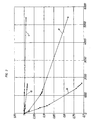
Figur 2 zeigt ein Diagramm, in welchem als Ordinate die relative Abnahme der Lumineszenzintensität und der Phasenverschiebung ΔΦ (Glg. 6) während der Beleuchtung des Sensors mit blauem Licht (Zentralwellenlänge 470nm einer Nichia NSPB500 LED) der Stärke Ee=20mW/cm2 bei T=37°C unter Umgebungsluft aufgetragen ist. Als Abszisse ist die Beleuchtungszeit in Minuten angegeben.FIG. 2 shows a diagram in which as ordinate the relative decrease of the luminescence intensity and the phase shift ΔΦ (Eq. 6) during the illumination of the sensor with blue light (central wavelength 470 nm of a Nichia NSPB500 LED) of intensity E e = 20 mW / cm 2 T = 37 ° C is applied under ambient air. The abscissa indicates the illumination time in minutes.
Zum Vergleich sind im Diagramm und in der Tabelle Meßdaten sowohl des DABCO enthaltenden Sensors (relative Intensität: Kurve a; relative Phasenverschiebung: Kurve c), als auch des DABCO-freien Sensors (relative Intensität: Kurve b; relative Phasenverscheibung: Kurve d) dargestellt. Wie aus dem Diagramm ersichtlich, ist sowohl die relative Phasenverschiebung (Abklingzeit), als auch - in stärkerem Maße - die relative Lumineszenzintensität vom Effekt des Photobleichens betroffen.For comparison, in the graph and in the table, measured data of both the DABCO-containing sensor (relative intensity: curve a; relative phase shift: curve c) and the DABCO-free sensor (relative intensity: curve b; relative phase shift: curve d) are shown , As can be seen from the graph, both the relative phase shift (decay time) and, to a greater extent, the relative luminescence intensity are affected by the photobleaching effect.
Ebenso kann man eine Reduktion der Stern-Volmer-Konstante parallel zur Reduktion der Abklingzeit nachweisen (Fig. 3). Sauerstoff begünstigt die Photodegeneration stark, jedoch ist möglicherweise auch ein thermischer Einfluß (in Abwesenheit von Sauerstoff) vorhanden. Zugabe von DABCO verringert in erster Linie durch physikalisches Löschen von Singulett-Sauerstoff den Effekt des Photobleichens wesentlich (siehe auch Tabelle). Die Tabelle enthält auch noch Meßdaten, die unter Verwendung anderer Additive gewonnen wurden. Der Bleicheffekt wird als relative Signalabnahme (Intensitätsabnahme ΔI16, Änderung der Phasenverschiebung ΔΦ16) nach 16stündiger Beleuchtung unter reinem Sauerstoff und sonstigen oben genannten Bedingungen quantifiziert.Similarly, one can detect a reduction of the Stern-Volmer constant parallel to the reduction of the decay time (FIG. 3). Oxygen strongly promotes the photodegeneration, but there may also be a thermal influence (in the absence of oxygen). Addition of DABCO substantially reduces the effect of photobleaching primarily by physically quenching singlet oxygen (see also Table). The table also contains measurement data obtained using other additives. The bleaching effect is quantified as a relative decrease in the signal (decrease in intensity ΔI 16 , change in the phase shift ΔΦ 16 ) after 16 hours illumination under pure oxygen and other conditions mentioned above.
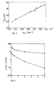
Die Wirkung von Additiven, wie DABCO, ist abhängig von deren Konzentration in der sensitiven Schicht. Fig. 4 zeigt die Konzentrationsabhängigkeit (Abszisse: Gew.-% DABCO) der Stabilisierung.The effect of additives such as DABCO is dependent on their concentration in the sensitive layer. Fig. 4 shows the concentration dependence (abscissa: wt .-% DABCO) of the stabilization.
Viele der möglichen Additive, auch DABCO, zeigen als Nebeneffekt auch eine Beeinflussung der photophysikalischen Eigenschaften des Indikators in der sensitiven Schicht. Fig. 5 zeigt die Reduktion der Abklingzeit mit zunehmender Konzentration an DABCO (Abszisse: Gew.-% DABCO): Dieser Effekt ist jedoch in diesem Fall, gemessen am Effekt der Stabilisierung, nicht sehr groß und stellt weder die Wirksamkeit des Additivs gegen Photozersetzung noch die Empfindlichkeit des Sensors in Frage.Many of the possible additives, including DABCO, also show, as a side effect, an influence on the photophysical properties of the indicator in the sensitive layer. Fig. 5 shows the reduction of the cooldown with increasing concentration of DABCO (abscissa: wt .-% DABCO): However, this effect is not very large in this case, measured on the effect of stabilization and neither the effectiveness of the additive against photodecomposition nor the sensitivity of the sensor in question.
Ähnlich gute Ergebnisse konnten erzielt werden, wenn anstelle des im Beispiel erwähnten Sensors folgende Sensoren verwendet wurden: Tris(1,10-phenanthrolin)-ruthenium(II)/PVC/DABCO; Tris(4,7-diphenyl-1,10-phenanthrolin)-ruthenium(II)/weichgemachtes PVC/DABCO; Tris(1,10-phenanthrolin)-ruthenium(II)/Kieselgel in Silikon/DABCO; Tris(2,2'-bipyridyl)-ruthenium(II)/Kieselgel in Silikon/DABCO; Tris(4,7-diphenyl-1,10-phenanthrolin)-ruthenium(II)/Polystyrol/Chimassorb 944; Tris(4,7-diphenyl-1,10-phenanthrolin)-ruthenium(II)/Polystyrol/DABCO+Chimassorb 944; Tris(4,7-diphenyl-1,10-phenanthrolin)-ruthenium(II)/Polystyrol/Tinuvin 770; Tris(4,7-diphenyl-1,10-phenanthrolin)-ruthenium(II)/Poly-(4-(N,N-dimethylamino)-styrol); Tris(4,7-diphenyl-1,10-phenanthrolin)-ruthenium(II)/Poly-(4-(N'N-dimethylamino)-styrol)-co-Polystyrol (97%); Platin(II)-octaethylporphyrin/PolystyroUDABCO; Platin(II)-octaethylporphyrin-keton/PolystyroUDABCO; Platin(II)-octaethylporphyrin-keton/PVC/Nichelat.Similarly good results could be obtained if, instead of the sensor mentioned in the example, the following sensors were used: tris (1,10-phenanthroline) ruthenium (II) / PVC / DABCO; Tris (4,7-diphenyl-1,10-phenanthroline) ruthenium (II) / plasticized PVC / DABCO; Tris (1,10-phenanthroline) ruthenium (II) / Silica gel in silicone / DABCO; Tris (2,2'-bipyridyl) ruthenium (II) / silica gel in silicone / DABCO; Tris (4,7-diphenyl-1,10-phenanthroline) ruthenium (II) / polystyrene / Chimassorb 944; Tris (4,7-diphenyl-1,10-phenanthroline) ruthenium (II) / polystyrene / DABCO + Chimassorb 944; Tris (4,7-diphenyl-1,10-phenanthroline) ruthenium (II) / polystyrene / Tinuvin 770; Tris (4,7-diphenyl-1,10-phenanthroline) ruthenium (II) / poly (4- (N, N-dimethylamino) styrene); Tris (4,7-diphenyl-1,10-phenanthroline) ruthenium (II) / poly (4- (N'N-dimethylamino) -styrene) -co-polystyrene (97%); Platinum (II) -octaethylporphyrin / PolystyroUDABCO; Platinum (II) -octaethylporphyrin ketone / PolystyroUDABCO; Platinum (II) -octaethylporphyrin ketone / PVC / Nichelat.
Relative Intensitätsänderung und relative Phasenverschiebungsänderung der Lumineszenz von Tris(4,7-diphenyl-1,10-phenanthrolin)rutheniumperchlorat in Polystyrol nach 16-stündiger Beleuchtung mit blauem Licht (470 nm) der Stärke 20 mW/cm2. Sensortemperatur T=37°C; Bleichen unter Sauerstoff; Messung unter Stickstoff. Unbehandelter Sensor vs. Varianten unter Zugabe stabilisierender Additive.
Claims (14)
- An optical sensor with a matrix comprising a luminescence indicator the luminescence of which can be quenched by oxygen,
characterized in that
the sensor comprises at least one agent capable of deactivating singlet oxygen for stabilizing the luminescence indicator and the matrix, wherein the agent is bound to the matrix or the luminescence indicator. - An optical sensor according to claim 1, characterized in that the agent for deactivating singlet oxygen comprises at least one amino group, preferably a tertiary amino group.
- An optical sensor according to claim 1, characterized in that the agent for deactivating singlet oxygen is a hindered amine light stabilizer (HALS).
- An optical sensor according to claim 1, characterized in that the agent for deactivating singlet oxygen is a transition metal complex.
- An optical sensor according to claim 4, characterized in that the transition metal complex is a complex of a dialkyldithio carbamate, dialkyldithio phosphate or a Schiff's base and a transition metal ion.
- An optical sensor according to claim 5, characterized in that the transition metal ion is Ni(II), Co(II), Zn(II) or Fe(III).
- An optical sensor according to claim 1, characterized in that the agent for deactivating singlet oxygen is a carotenoid.
- An optical sensor according to any of claims 1 to 3, characterized in that the agent is bound to the luminescence indicator via a group -(CH2)n-, wherein n is an integer from 3 to 20.
- An optical sensor according to any of claims 1 to 8, characterized in that the matrix is a polymer.
- An optical sensor according to claim 9, characterized in that the polymer is polystyrene, polyvinyl chloride, plasticized polyvinyl chloride, polymethyl methacrylate, plasticized polymethyl methacrylate, a polymethyl methacrylate/cellulose-acetyl-butyral mixture, a silica gel, a sol gel, a hydrogel, a silicone, poly-α-methylstyrene, a polysulfone, ethyl cellulose, cellulose triacetate, polytetrafluoroethylene, a polyester, polybutadiene, polystyrene-co-butadiene, polyurethane, polyvinyl butyral, polyethyl acrylate or poly-2-hydroxyethyl methacrylate.
- An optical sensor according to claim 9, characterized in that the polymer is produced from monomers which carry, at least partially, an amino group, preferably a tertiary amino group.
- An optical sensor according to any of claims 1 to 11, characterized in that the luminescence indicator is a tris-chelate complex of ruthenium(II), osmium(II), rhodium(III) or iridium(III), a metalloporphyrin or a metalloporphyrin ketone of platinum or palladium, a lanthanide complex of terbium or a polycyclic aromatic hydrocarbon.
- An optical sensor configuration comprising an optical sensor, a light source for generating light for exciting the luminescence indicator and a measuring means for measuring at least one optical property of the luminescence indicator,
characterized in that
an optical sensor according to any of claims 1 to 12 is provided. - A method of determining an analyte in a gaseous or liquid sample by means of an optical sensor which is contacted with the sample either directly or indirectly,
characterized in that
a sensor according to any of claims 1 to 12 is used.
Priority Applications (1)
| Application Number | Priority Date | Filing Date | Title |
|---|---|---|---|
| EP06022007A EP1757924B1 (en) | 1997-10-03 | 1998-10-02 | Optical chemical sensor |
Applications Claiming Priority (3)
| Application Number | Priority Date | Filing Date | Title |
|---|---|---|---|
| AT0167897A AT409306B (en) | 1997-10-03 | 1997-10-03 | OPTICAL CHEMICAL SENSOR |
| AT1678/97 | 1997-10-03 | ||
| AT167897 | 1997-10-03 |
Related Child Applications (1)
| Application Number | Title | Priority Date | Filing Date |
|---|---|---|---|
| EP06022007A Division EP1757924B1 (en) | 1997-10-03 | 1998-10-02 | Optical chemical sensor |
Publications (3)
| Publication Number | Publication Date |
|---|---|
| EP0907074A2 EP0907074A2 (en) | 1999-04-07 |
| EP0907074A3 EP0907074A3 (en) | 1999-09-08 |
| EP0907074B1 true EP0907074B1 (en) | 2006-12-06 |
Family
ID=3518628
Family Applications (2)
| Application Number | Title | Priority Date | Filing Date |
|---|---|---|---|
| EP06022007A Expired - Lifetime EP1757924B1 (en) | 1997-10-03 | 1998-10-02 | Optical chemical sensor |
| EP98890284A Expired - Lifetime EP0907074B1 (en) | 1997-10-03 | 1998-10-02 | Optical chemical sensor |
Family Applications Before (1)
| Application Number | Title | Priority Date | Filing Date |
|---|---|---|---|
| EP06022007A Expired - Lifetime EP1757924B1 (en) | 1997-10-03 | 1998-10-02 | Optical chemical sensor |
Country Status (5)
| Country | Link |
|---|---|
| US (1) | US6254829B1 (en) |
| EP (2) | EP1757924B1 (en) |
| JP (1) | JPH11194094A (en) |
| AT (1) | AT409306B (en) |
| DE (2) | DE59814271D1 (en) |
Cited By (3)
| Publication number | Priority date | Publication date | Assignee | Title |
|---|---|---|---|---|
| DE102017114535A1 (en) | 2017-06-29 | 2019-01-03 | Endress+Hauser Conducta Gmbh+Co. Kg | Sensor membrane, sensor cap and optical sensor |
| DE102017118504A1 (en) | 2017-08-14 | 2019-02-14 | Endress+Hauser Conducta Gmbh+Co. Kg | Protection device for an optochemical sensor and corresponding optochemical sensor |
| DE102022134274A1 (en) | 2022-12-21 | 2024-06-27 | Endress+Hauser Conducta Gmbh+Co. Kg | Sensor element for an optochemical sensor |
Families Citing this family (40)
| Publication number | Priority date | Publication date | Assignee | Title |
|---|---|---|---|---|
| US6395506B1 (en) * | 1991-04-18 | 2002-05-28 | Becton, Dickinson And Company | Device for monitoring cells |
| EP0862648B1 (en) | 1995-11-22 | 2004-10-06 | Medtronic MiniMed, Inc. | Detection of biological molecules using chemical amplification and optical sensors |
| DE59813665D1 (en) * | 1998-03-07 | 2006-09-07 | Bosch Gmbh Robert | OPTICAL SENSOR |
| EP1080162B1 (en) | 1998-05-05 | 2004-03-10 | Massachusetts Institute Of Technology | Emissive polymers and devices incorporating these polymers |
| US20050147534A1 (en) | 1998-05-05 | 2005-07-07 | Massachusetts Institute Of Technology | Emissive sensors and devices incorporating these sensors |
| US6331438B1 (en) | 1999-11-24 | 2001-12-18 | Iowa State University Research Foundation, Inc. | Optical sensors and multisensor arrays containing thin film electroluminescent devices |
| NL1014464C2 (en) * | 2000-02-22 | 2001-08-24 | Tno | Optical sensor for measuring oxygen. |
| DE10101576B4 (en) * | 2001-01-15 | 2016-02-18 | Presens Precision Sensing Gmbh | Optical sensor and sensor field |
| DE10123079A1 (en) * | 2001-05-11 | 2002-11-21 | Draeger Medical Ag | Device for optically measuring the oxygen concentration in a gas stream includes a film comprising a luminescent dye and an amorphous 2,2-bistrifluoromethyl-4,5-difluoro-1,3-dioxole (co)polymer |
| GB0302489D0 (en) * | 2003-02-04 | 2003-03-05 | Bae Systems Plc | Improvements relating to pressure sensitive paint |
| US20040241880A1 (en) * | 2003-05-30 | 2004-12-02 | Leproust Eric M. | Ligand array assays having reduced fluorescent dye degradation and compositions for practicing the same |
| WO2006034081A2 (en) * | 2004-09-17 | 2006-03-30 | Massachusetts Institute Of Technology | Polymers for analyte detection |
| WO2007009125A2 (en) * | 2005-07-14 | 2007-01-18 | Nano-Ditech Corporation | Microfluidic devices and methods of preparing and using the same |
| JP4727349B2 (en) * | 2005-08-30 | 2011-07-20 | 三菱瓦斯化学株式会社 | Oxygen detector composition |
| US20070143032A1 (en) * | 2005-09-15 | 2007-06-21 | Carl Zeiss Smt Ag | Apparatus and method for the detection of a surface reaction, especially for cleaning of an arbitrary two-dimensional surface or three-dimensional body |
| DE102006001642B4 (en) * | 2006-01-11 | 2008-02-21 | Sartorius Biotech Gmbh | Oxygen sensor and measuring method |
| US20070243618A1 (en) * | 2006-04-11 | 2007-10-18 | Oxysense, Inc. | Device and method for non-invasive oxygen sensing of sealed packages |
| US8283423B2 (en) | 2006-09-29 | 2012-10-09 | Massachusetts Institute Of Technology | Polymer synthetic technique |
| US8802447B2 (en) * | 2006-10-05 | 2014-08-12 | Massachusetts Institute Of Technology | Emissive compositions with internal standard and related techniques |
| US20090215189A1 (en) | 2006-10-27 | 2009-08-27 | Massachusetts Institute Of Technology | Sensor of species including toxins and chemical warfare agents |
| EP2099855A2 (en) * | 2006-11-20 | 2009-09-16 | Gas Sensors Solutions Limited | Oxygen sensitive material, sensors, sensor systems with improved photostability |
| US8838195B2 (en) * | 2007-02-06 | 2014-09-16 | Medtronic Minimed, Inc. | Optical systems and methods for ratiometric measurement of blood glucose concentration |
| EP2162057A1 (en) * | 2007-05-10 | 2010-03-17 | Glumetrics, Inc. | Equilibrium non-consuming fluorescence sensor for real time intravascular glucose measurement |
| EP2020597A1 (en) | 2007-08-02 | 2009-02-04 | Mettler-Toledo AG | Opto-chemical sensor |
| EP2217316A4 (en) | 2007-11-21 | 2013-01-16 | Glumetrics Inc | Use of an equilibrium intravascular sensor to achieve tight glycemic control |
| DE102008019889B4 (en) * | 2008-04-21 | 2018-06-14 | Compur Monitors Gmbh & Co. Kg | Indicator and indicator plaque for the detection of gases |
| JP2011529577A (en) * | 2008-07-28 | 2011-12-08 | センサーズ・フォー・メデセン・アンド・サイエンス・インコーポレーテッド | System and method for optical measurement of analyte concentration |
| EP2483679A4 (en) | 2009-09-30 | 2013-04-24 | Glumetrics Inc | Sensors with thromboresistant coating |
| US8467843B2 (en) | 2009-11-04 | 2013-06-18 | Glumetrics, Inc. | Optical sensor configuration for ratiometric correction of blood glucose measurement |
| JP2013519101A (en) * | 2010-02-08 | 2013-05-23 | グルメトリクス, インコーポレイテッド | Antioxidant protection of chemical sensors |
| DE102011007546A1 (en) * | 2011-04-15 | 2012-10-18 | Humboldt-Universität Zu Berlin | Measuring device for measuring singlet oxygen luminescence |
| DE102012104688A1 (en) | 2012-05-30 | 2013-12-05 | Hamilton Bonaduz Ag | Optical sensor element |
| DE102012111686A1 (en) * | 2012-11-30 | 2014-06-05 | Hamilton Bonaduz Ag | Chemically stable sensor |
| EP3526801B1 (en) | 2016-10-14 | 2022-12-07 | C3Nano Inc. | Stabilized sparse metal conductive films and solutions for delivery of stabilizing compounds |
| AT520591B1 (en) * | 2017-10-30 | 2020-10-15 | Technische Farben Ges B R | Sensor ink, method for producing a fluorescence sensor with the sensor ink and sensor |
| DE102018116345A1 (en) * | 2018-07-05 | 2020-01-09 | Endress+Hauser Conducta Gmbh+Co. Kg | Sensor membrane, sensor cap and method for applying a sensor membrane |
| CN111693515B (en) * | 2020-05-07 | 2022-06-17 | 四川轻化工大学 | A kind of flow electrochemiluminescence real-time detection device and detection method |
| US11874221B2 (en) | 2021-01-26 | 2024-01-16 | Yokogawa Electric Corporation | Measurement of dissolved oxygen using optical radiation induced luminescence |
| EP4437340A4 (en) * | 2021-11-26 | 2025-10-01 | Ip Science Ltd | DEVICE AND METHOD FOR TREATING OXYGEN DEFICIENCY IN TISSUE |
| GB2638199A (en) * | 2024-02-15 | 2025-08-20 | Senoptica Tech Limited | Colorimetric Sensor and use thereof |
Family Cites Families (37)
| Publication number | Priority date | Publication date | Assignee | Title |
|---|---|---|---|---|
| US3612866A (en) | 1969-07-08 | 1971-10-12 | Brian Stevens | Instrument for determining oxygen quantities by measuring oxygen quenching of fluorescent radiation |
| DE2508637C3 (en) | 1975-02-28 | 1979-11-22 | Max-Planck-Gesellschaft Zur Foerderung Der Wissenschaften E.V., 3400 Goettingen | Arrangement for the optical measurement of blood gases |
| US4720356A (en) | 1982-03-22 | 1988-01-19 | American Optical Corporation | Photochromic composition resistant to fatigue |
| US4428859A (en) | 1982-11-12 | 1984-01-31 | University Patents, Inc. | Stabilizer of organic dye lasers |
| AT379688B (en) * | 1982-11-22 | 1986-02-10 | List Hans | SENSOR ELEMENT FOR DETERMINING THE O2 CONTENT OF A SAMPLE |
| AT377095B (en) * | 1982-11-23 | 1985-02-11 | List Hans | SENSOR ELEMENT FOR DETERMINING THE O2 CONTENT OF A SAMPLE AND METHOD FOR PRODUCING THE SAME |
| US5030420A (en) | 1982-12-23 | 1991-07-09 | University Of Virginia Alumni Patents Foundation | Apparatus for oxygen determination |
| CA1261717A (en) * | 1982-12-23 | 1989-09-26 | John R. Bacon | Method and apparatus for oxygen determination |
| DE3320752A1 (en) | 1983-06-09 | 1984-12-13 | Wolfgang Prof. Dr.Dr. 6500 Mainz Barnikol | LUMINESCENT LAYERS FOR USE IN DEVICES FOR DETERMINING THE OXYGEN CONCENTRATION IN GASES AND THE LIKE BY MEASURING THE LUMINESCENT REDUCTION |
| US4752115A (en) | 1985-02-07 | 1988-06-21 | Spectramed, Inc. | Optical sensor for monitoring the partial pressure of oxygen |
| US4810655A (en) | 1985-07-03 | 1989-03-07 | Abbott Laboratories | Method for measuring oxygen concentration |
| US5043286A (en) | 1985-07-03 | 1991-08-27 | Abbott Laboratories | Method and sensor for measuring oxygen concentration |
| US4849172A (en) * | 1986-04-18 | 1989-07-18 | Minnesota Mining And Manufacturing Company | Optical sensor |
| JPS6312942A (en) | 1986-07-03 | 1988-01-20 | Rikagaku Kenkyusho | Oxygen concentration measurement element |
| GB8621261D0 (en) | 1986-09-03 | 1986-10-08 | Barnard G J R | Enhanced luminescent assay |
| US5070158A (en) | 1987-03-12 | 1991-12-03 | Hewlett-Packard Company | Covalently labeled siloxane polymers |
| DE3778363D1 (en) | 1987-09-11 | 1992-05-21 | Agfa Gevaert Nv | POLYMERIC PHOSPHONIUM MIXER AND PHOTOGRAPHIC ELEMENT THAT CONTAINS THIS. |
| DK576187D0 (en) * | 1987-11-03 | 1987-11-03 | Radiometer As | METHOD OF DETERMINING OXYGEN CONCENTRATION |
| US5242835A (en) | 1987-11-03 | 1993-09-07 | Radiometer A/S | Method and apparatus for determining the concentration of oxygen |
| US5173432A (en) * | 1987-12-14 | 1992-12-22 | The Dow Chemical Company | Apparatus and method for measuring the concentration or partial pressure of oxygen |
| US5047350A (en) * | 1989-01-19 | 1991-09-10 | Eastman Kodak Company | Material and method for oxygen sensing |
| US5225113A (en) | 1989-02-10 | 1993-07-06 | Enichem Synthesis S.P.A. | Photochromatic composition endowed with light fatigue resistance and photochromatic articles which contain it |
| US5087388A (en) | 1990-02-26 | 1992-02-11 | Research Corporation Technologies, Inc. | Cartridge for extending the lifetime of dyes in dye lasers |
| US5223380A (en) * | 1990-05-14 | 1993-06-29 | Fuji Photo Film Co., Ltd. | Color developing agent and process for forming image |
| IT1243719B (en) | 1990-09-18 | 1994-06-21 | Enichem Sintesi | STABILIZING MIXTURE FOR PHOTOCROMATIC ACTIVITY COMPOUNDS |
| US5409666A (en) * | 1991-08-08 | 1995-04-25 | Minnesota Mining And Manufacturing Company | Sensors and methods for sensing |
| ES2113547T3 (en) * | 1992-07-31 | 1998-05-01 | Behringwerke Ag | PHOTOACTIVABLE CHEMIOLUMINISCENT MATRICES. |
| US5403834A (en) * | 1992-12-07 | 1995-04-04 | Eukarion, Inc. | Synthetic catalytic free radical scavengers useful as antioxidants for prevention and therapy of disease |
| TW267178B (en) * | 1993-07-13 | 1996-01-01 | Ciba Geigy | |
| US5462880A (en) | 1993-09-13 | 1995-10-31 | Optical Sensors Incorporated | Ratiometric fluorescence method to measure oxygen |
| US5511547A (en) | 1994-02-16 | 1996-04-30 | Biomedical Sensors, Ltd. | Solid state sensors |
| US5534646A (en) * | 1994-08-31 | 1996-07-09 | Ciba-Geigy Corporation | Substituted 1,3,2,4-diazadiphosphetidines and compositions stabilized therewith |
| DE69515062T2 (en) | 1994-11-28 | 2000-09-14 | Minnesota Mining And Mfg. Co., St. Paul | OBJECTS WITH PERMANENT COLOR AND / OR FLUORESCENT CHARACTERISTICS |
| US5816238A (en) * | 1994-11-28 | 1998-10-06 | Minnesota Mining And Manufacturing Company | Durable fluorescent solar collectors |
| US5700077A (en) * | 1995-03-23 | 1997-12-23 | Minnesota Mining And Manufacturing Company | Line light source including fluorescent colorant |
| US5714121A (en) | 1995-09-28 | 1998-02-03 | Optical Sensors Incorporated | Optical carbon dioxide sensor, and associated methods of manufacture |
| US5827904A (en) * | 1996-09-27 | 1998-10-27 | Hahn; David | Medical implant composition |
-
1997
- 1997-10-03 AT AT0167897A patent/AT409306B/en not_active IP Right Cessation
-
1998
- 1998-09-28 US US09/161,841 patent/US6254829B1/en not_active Expired - Lifetime
- 1998-10-02 EP EP06022007A patent/EP1757924B1/en not_active Expired - Lifetime
- 1998-10-02 DE DE59814271T patent/DE59814271D1/en not_active Expired - Lifetime
- 1998-10-02 DE DE59813836T patent/DE59813836D1/en not_active Expired - Lifetime
- 1998-10-02 EP EP98890284A patent/EP0907074B1/en not_active Expired - Lifetime
- 1998-10-05 JP JP10283151A patent/JPH11194094A/en active Pending
Cited By (3)
| Publication number | Priority date | Publication date | Assignee | Title |
|---|---|---|---|---|
| DE102017114535A1 (en) | 2017-06-29 | 2019-01-03 | Endress+Hauser Conducta Gmbh+Co. Kg | Sensor membrane, sensor cap and optical sensor |
| DE102017118504A1 (en) | 2017-08-14 | 2019-02-14 | Endress+Hauser Conducta Gmbh+Co. Kg | Protection device for an optochemical sensor and corresponding optochemical sensor |
| DE102022134274A1 (en) | 2022-12-21 | 2024-06-27 | Endress+Hauser Conducta Gmbh+Co. Kg | Sensor element for an optochemical sensor |
Also Published As
| Publication number | Publication date |
|---|---|
| US6254829B1 (en) | 2001-07-03 |
| JPH11194094A (en) | 1999-07-21 |
| DE59813836D1 (en) | 2007-01-18 |
| EP1757924A3 (en) | 2007-04-11 |
| EP0907074A3 (en) | 1999-09-08 |
| AT409306B (en) | 2002-07-25 |
| ATA167897A (en) | 2001-11-15 |
| EP1757924A2 (en) | 2007-02-28 |
| EP0907074A2 (en) | 1999-04-07 |
| DE59814271D1 (en) | 2008-09-25 |
| EP1757924B1 (en) | 2008-08-13 |
Similar Documents
| Publication | Publication Date | Title |
|---|---|---|
| EP0907074B1 (en) | Optical chemical sensor | |
| EP1000345B1 (en) | Method and device for referencing fluorescence intensity signals | |
| DE3346810C2 (en) | Device for measuring the oxygen concentration in a gaseous or liquid medium | |
| EP1346223B1 (en) | Reagent for luminescence optical determination of an analyte | |
| EP0870189B1 (en) | Optical temperature sensors and optical-chemical sensors with optical temperature compensation | |
| DE3876037T2 (en) | CARBON DIOXIDE SENSOR. | |
| DE69401717T2 (en) | Process for the activation of polyanionic, fluorescent dyes in weakly dielectric media with quaternary onium compounds | |
| Eaton et al. | Effect of humidity on the response characteristics of luminescent PtOEP thin film optical oxygen sensors | |
| DE4210970C2 (en) | Process for the simultaneous optical qualitative and quantitative detection of different molecules of a mixture marked with fluorochromes or fluorogens by means of laser spectroscopy | |
| Coldur et al. | Usage of thiocyanate-based ionic liquid as new optical sensor reagent: Absorption and emission based selective determination of Fe (III) ions | |
| EP2856143B1 (en) | Optical sensor element | |
| DE3817732A1 (en) | METHOD FOR THE CONTINUOUS, QUANTITATIVE DETERMINATION OF SULFUR DIOXIDE AND ARRANGEMENT FOR IMPLEMENTING THE METHOD | |
| EP2145925B1 (en) | Use of a long-wave emitting cyanine compound as an NIR fluorescence standard and kit to calibrate photoluminescence measuring system | |
| EP0578630A1 (en) | Sensor membrane of an optical sensor for the determination of a physical or chemical parameter of a sample | |
| EP1141729B1 (en) | Optical-chemical sensor for detecting chloride | |
| DE19829657A1 (en) | Method and device for referencing fluorescence intensity signals | |
| EP0397641B1 (en) | Method for quantitatively determining a chemical parameter of a sample | |
| DE19935180C2 (en) | Solar cell sensors, process for their manufacture and their application | |
| Derinkuyu et al. | Emission based fiber optic pH sensing with Schiff bases bearing dimethylamino groups | |
| WO2003036293A1 (en) | Method for simultaneous optical measurement of a ph-value and dissolved oxygen content | |
| AT506177B1 (en) | OPTICAL SENSOR | |
| WO2007014710A2 (en) | Irreversible passive gas sensor | |
| Hrdlovič et al. | Spectral characteristics of probes based on ionic derivatives of pyrene in polar polymer matrices | |
| DE102019124795A1 (en) | Optical pH sensor | |
| DE4213268A1 (en) | Method for producing a sensor for determining the oxygen content of a sample |
Legal Events
| Date | Code | Title | Description |
|---|---|---|---|
| PUAI | Public reference made under article 153(3) epc to a published international application that has entered the european phase |
Free format text: ORIGINAL CODE: 0009012 |
|
| AK | Designated contracting states |
Kind code of ref document: A2 Designated state(s): DE FR GB |
|
| AX | Request for extension of the european patent |
Free format text: AL;LT;LV;MK;RO;SI |
|
| PUAL | Search report despatched |
Free format text: ORIGINAL CODE: 0009013 |
|
| AK | Designated contracting states |
Kind code of ref document: A3 Designated state(s): AT BE CH CY DE DK ES FI FR GB GR IE IT LI LU MC NL PT SE |
|
| AX | Request for extension of the european patent |
Free format text: AL;LT;LV;MK;RO;SI |
|
| 17P | Request for examination filed |
Effective date: 20000308 |
|
| AKX | Designation fees paid |
Free format text: DE FR GB |
|
| RAP1 | Party data changed (applicant data changed or rights of an application transferred) |
Owner name: AVL MEDICAL INSTRUMENTS AG |
|
| RAP1 | Party data changed (applicant data changed or rights of an application transferred) |
Owner name: F. HOFFMANN-LA ROCHE AG |
|
| GRAP | Despatch of communication of intention to grant a patent |
Free format text: ORIGINAL CODE: EPIDOSNIGR1 |
|
| GRAS | Grant fee paid |
Free format text: ORIGINAL CODE: EPIDOSNIGR3 |
|
| GRAA | (expected) grant |
Free format text: ORIGINAL CODE: 0009210 |
|
| AK | Designated contracting states |
Kind code of ref document: B1 Designated state(s): DE FR GB |
|
| REG | Reference to a national code |
Ref country code: GB Ref legal event code: FG4D Free format text: NOT ENGLISH |
|
| REF | Corresponds to: |
Ref document number: 59813836 Country of ref document: DE Date of ref document: 20070118 Kind code of ref document: P |
|
| GBV | Gb: ep patent (uk) treated as always having been void in accordance with gb section 77(7)/1977 [no translation filed] |
Effective date: 20061206 |
|
| EN | Fr: translation not filed | ||
| PLBE | No opposition filed within time limit |
Free format text: ORIGINAL CODE: 0009261 |
|
| STAA | Information on the status of an ep patent application or granted ep patent |
Free format text: STATUS: NO OPPOSITION FILED WITHIN TIME LIMIT |
|
| 26N | No opposition filed |
Effective date: 20070907 |
|
| PG25 | Lapsed in a contracting state [announced via postgrant information from national office to epo] |
Ref country code: GB Free format text: LAPSE BECAUSE OF FAILURE TO SUBMIT A TRANSLATION OF THE DESCRIPTION OR TO PAY THE FEE WITHIN THE PRESCRIBED TIME-LIMIT Effective date: 20061206 |
|
| PG25 | Lapsed in a contracting state [announced via postgrant information from national office to epo] |
Ref country code: FR Free format text: LAPSE BECAUSE OF FAILURE TO SUBMIT A TRANSLATION OF THE DESCRIPTION OR TO PAY THE FEE WITHIN THE PRESCRIBED TIME-LIMIT Effective date: 20070727 |
|
| PG25 | Lapsed in a contracting state [announced via postgrant information from national office to epo] |
Ref country code: FR Free format text: LAPSE BECAUSE OF FAILURE TO SUBMIT A TRANSLATION OF THE DESCRIPTION OR TO PAY THE FEE WITHIN THE PRESCRIBED TIME-LIMIT Effective date: 20061206 |
|
| PGFP | Annual fee paid to national office [announced via postgrant information from national office to epo] |
Ref country code: DE Payment date: 20171027 Year of fee payment: 20 |
|
| REG | Reference to a national code |
Ref country code: DE Ref legal event code: R071 Ref document number: 59813836 Country of ref document: DE |