EP0907032B1 - Halteelement - Google Patents
Halteelement Download PDFInfo
- Publication number
- EP0907032B1 EP0907032B1 EP98118954A EP98118954A EP0907032B1 EP 0907032 B1 EP0907032 B1 EP 0907032B1 EP 98118954 A EP98118954 A EP 98118954A EP 98118954 A EP98118954 A EP 98118954A EP 0907032 B1 EP0907032 B1 EP 0907032B1
- Authority
- EP
- European Patent Office
- Prior art keywords
- holding element
- holding
- longitudinal
- longitudinal plane
- claws
- Prior art date
- Legal status (The legal status is an assumption and is not a legal conclusion. Google has not performed a legal analysis and makes no representation as to the accuracy of the status listed.)
- Expired - Lifetime
Links
- 210000000078 claw Anatomy 0.000 claims abstract description 45
- 210000002105 tongue Anatomy 0.000 claims description 22
- 230000009467 reduction Effects 0.000 claims description 6
- 229910000639 Spring steel Inorganic materials 0.000 claims description 3
- 239000000463 material Substances 0.000 claims description 2
- 230000007704 transition Effects 0.000 claims 1
- 238000010276 construction Methods 0.000 abstract 1
- 125000006850 spacer group Chemical group 0.000 description 20
- 238000004519 manufacturing process Methods 0.000 description 4
- 238000011161 development Methods 0.000 description 2
- 230000018109 developmental process Effects 0.000 description 2
- 239000002184 metal Substances 0.000 description 2
- 230000001419 dependent effect Effects 0.000 description 1
- 238000006073 displacement reaction Methods 0.000 description 1
- 238000005553 drilling Methods 0.000 description 1
- 238000009434 installation Methods 0.000 description 1
- 210000002414 leg Anatomy 0.000 description 1
- 238000003825 pressing Methods 0.000 description 1
- 238000004080 punching Methods 0.000 description 1
- 238000005096 rolling process Methods 0.000 description 1
- 238000000926 separation method Methods 0.000 description 1
- 238000003892 spreading Methods 0.000 description 1
- 210000000689 upper leg Anatomy 0.000 description 1
Images

Classifications
-
- F—MECHANICAL ENGINEERING; LIGHTING; HEATING; WEAPONS; BLASTING
- F16—ENGINEERING ELEMENTS AND UNITS; GENERAL MEASURES FOR PRODUCING AND MAINTAINING EFFECTIVE FUNCTIONING OF MACHINES OR INSTALLATIONS; THERMAL INSULATION IN GENERAL
- F16B—DEVICES FOR FASTENING OR SECURING CONSTRUCTIONAL ELEMENTS OR MACHINE PARTS TOGETHER, e.g. NAILS, BOLTS, CIRCLIPS, CLAMPS, CLIPS OR WEDGES; JOINTS OR JOINTING
- F16B37/00—Nuts or like thread-engaging members
- F16B37/02—Nuts or like thread-engaging members made of thin sheet material
-
- F—MECHANICAL ENGINEERING; LIGHTING; HEATING; WEAPONS; BLASTING
- F16—ENGINEERING ELEMENTS AND UNITS; GENERAL MEASURES FOR PRODUCING AND MAINTAINING EFFECTIVE FUNCTIONING OF MACHINES OR INSTALLATIONS; THERMAL INSULATION IN GENERAL
- F16B—DEVICES FOR FASTENING OR SECURING CONSTRUCTIONAL ELEMENTS OR MACHINE PARTS TOGETHER, e.g. NAILS, BOLTS, CIRCLIPS, CLAMPS, CLIPS OR WEDGES; JOINTS OR JOINTING
- F16B37/00—Nuts or like thread-engaging members
- F16B37/04—Devices for fastening nuts to surfaces, e.g. sheets, plates
- F16B37/041—Releasable devices
- F16B37/043—Releasable devices with snap action
-
- F—MECHANICAL ENGINEERING; LIGHTING; HEATING; WEAPONS; BLASTING
- F16—ENGINEERING ELEMENTS AND UNITS; GENERAL MEASURES FOR PRODUCING AND MAINTAINING EFFECTIVE FUNCTIONING OF MACHINES OR INSTALLATIONS; THERMAL INSULATION IN GENERAL
- F16B—DEVICES FOR FASTENING OR SECURING CONSTRUCTIONAL ELEMENTS OR MACHINE PARTS TOGETHER, e.g. NAILS, BOLTS, CIRCLIPS, CLAMPS, CLIPS OR WEDGES; JOINTS OR JOINTING
- F16B7/00—Connections of rods or tubes, e.g. of non-circular section, mutually, including resilient connections
- F16B7/04—Clamping or clipping connections
- F16B7/0433—Clamping or clipping connections for rods or tubes being in parallel relationship
Definitions
- the invention relates to a holding element according to the preamble of claim 1 specified characteristics.
- a holding element with holding claws which with longitudinal grooves a profile rail for establishing a non-positive and / or positive connection in Intervention can be brought.
- the holding element contains a housing, which for connection to a another profile can be used in the hollow chamber. For connection with other components, such as Connection angles, support elements or the like, this holding element is not easy suitable.
- a holding element which has a central part and this has arranged holding claws.
- the holding part is partially in a bore
- Component can be used and contains holding claws which attack on an underside of the component.
- a profile is provided with a hole through which a Fastened by the fastener formed.
- the fastener is also in a connecting element of the holding element can be screwed in, by tightening the fastening element the component and the profile are clamped against each other.
- Both that Profile as well as the component must have the bores mentioned, whereby a certain mutual positioning and a mutual alignment accordingly variable installation conditions is not easily feasible.
- the drilling of the holes Both in the profile and in the component to be connected to it requires one additional assembly effort.
- the connection of the component with a profile rail, which Having longitudinal edges undercut longitudinal grooves is not readily possible.
- a holding element is known from EP-A-0 322 267, which essentially consists of two Parts formed in a U-shape.
- the first part contains openings in thighs, in which resilient claws of the second part engage.
- the holding element is inside a U-shaped carrier used, the legs of the first part by means of said Retaining claws of the second part are clamped against the inner surface of the U-shaped carrier.
- the U-shaped supports and both parts of the holding element have mutually aligned bores on, for a screw for connection to a component, the screw in a with the internal second part connected internal thread can be screwed. Connect to a profile rail which has undercut longitudinal grooves in the area of its longitudinal edges, is not easily produced with this holding element.
- the invention is based, with little constructive the task Effort to train the holding element in such a way that a functionally reliable connection of the Component with the profile is made possible, which as a profile rail with undercut Longitudinal grooves are formed on the longitudinal edges.
- the holding element should have a low manufacturing cost require and a safe and permanent connection with the mounting rail put.
- the handling during assembly should be simplified and the assembly time should be reduced to one Minimum be reduced.
- the holding element according to the invention is in particular a sheet metal bracket Spring steel, trained and has the two angled on its two longitudinal edges Retaining claws which are used to engage the longitudinal grooves of the profile or the profile rail are provided.
- the holding element contains a connecting element, which together is provided with a fastening body for connection to a component.
- the fastening body is expediently designed as a bolt which has inclined surfaces, Has threaded surfaces, pins, cams or the like, which correspond with Surfaces, grooves or the like of the holding element and in particular its Sleeve or approach can be brought into engagement. So the mounting body as a screw be formed, which in a thread of the sleeve or the neck of the holding element intervenes.
- connection can also be made in the manner of a bayonet lock be designed such that the bolt has radial pins or cams, which in corresponding grooves or slots of the holding element, in particular engage its sleeve or neck. It is essential for all embodiments that an axial clamping force is exerted by means of the connecting element such that the Retaining claws are pressed and tightened.
- the connecting element for the fastening body or bolt is provided, by means of which the component is connected. That's how it is, for example Thread in the middle part of the holding element, preferably in the sleeve or the annular Approach provided, which has a predetermined height.
- the connecting element especially the sleeve or the attachment with the thread, which is an internal thread is designed according to the external thread of the screw mentioned, is on the Arranged outside, while the holding claws to the opposite inside of the holding element are directed and angled.
- the connecting element is on the Arranged outside, while the holding claws to the opposite inside of the holding element are directed and angled.
- the fastening body can instead of the screw mentioned in the context of the invention be designed as a bolt with a radial pin or cam, with which the Connecting element of the holding element corresponds, wherein the connecting element is designed in particular as a bayonet sleeve. So the connecting element or the bayonet sleeve have a basically L-shaped slot with a longitudinal part and a cross section.
- connection with the component of the fastening body in the connecting element or the sleeve of the Retaining element inserted such that the radial pin or cam first in the slot longitudinal part engages and then after appropriate rotation of the bolt in the cross section engages, at the same time an axial longitudinal force to the axial according to the invention Tensioning the holding element in particular by appropriate inclination of the cross member is achieved.
- the width or the according to the invention the diameter of this recess is larger than the outside diameter of the approach, which can thus engage in this recess. Furthermore the width or the diameter is so large that when tightening the Screw the tension according to the invention by increasing the distance of the free ends of the claws with respect to the middle part and / or by reinforced, oppositely directed lateral pressing of the opposing ones Holding claws in the two longitudinal grooves of the profile rail is effected.
- the holding element also contains at least two diametrically arranged tongues, which are also arranged angled to the inside are and which are used in particular for centering on the profile rail.
- the Tongues expediently overlap the parallel outer edges of those Profile surface on which the longitudinal grooves and the engaging therein on both sides Holding claws of the holding element are located.
- the holding element contains spacer elements, which are one definable distance of the holding element and in particular its middle part to specify the opposite surface of the component to be connected.
- These distance elements can be conveniently used as angled parts, especially in shape be formed by claws, which, like the thread approach from the middle part in the protrude in the same direction opposite to the claws.
- the spacer elements are expediently punched out and angling of predetermined parts of the holding element and as well as the tongues already mentioned in one piece with the holding element.
- the spacer elements are expediently located on the associated with tip or end regions Surface of the component, with a high surface pressure and / or reliable fixation is guaranteed.
- Fig. 1 shows the one-piece made of sheet metal, namely spring steel, holding element with the two claws 4, 6 angled towards the inside, between which one Middle part 8 lies.
- a Connecting element in the form of an annular extension 10 with an internal thread 12 provided for a screw not shown here.
- the internal thread 12 is made by rolling.
- the two on the longitudinal edges 14, 16 of the holding element to the inside 2 C-like angled holding claws 14, 16 are in accordance with the contour of the profile as well its longitudinal grooves are formed and project with their curved free ends 18, 20 inwards to the longitudinal plane 22.
- the free ends 18, 20 are spaced 24 to each other, which is much smaller than the distance 26 between the longitudinal edges 14, 16.
- the holding claws 4, 6 are designed such that the to the longitudinal plane 22 angled free ends 18, 20 in the undercut longitudinal grooves of the intervene mentioned profile. It is important here that the distance 24 of the free ends 18, 20 is smaller than the width of the surface of the assigned profile.
- the holding claws 4, 6 also contain in the downwardly directed central webs 34, 36 openings 38, 40. If necessary, a tool, like a screwdriver, can be used to hold the holding element in place or clip on in the direction of arrow 42 to loosen the profile again can.
- the holding element has in the attachment area of the holding claws 4, 6 on the central part 8 material reductions or openings 44, 46.
- These openings 44, 46 are expediently symmetrical on both sides of the Longitudinal plane 22 and cause a reduction in spring stiffness in this area.
- the reduction in rigidity specified in this way the spreading of the Retaining claws 4, 6 easier when placed on the profile.
- the holding element contains at least two diametrically with respect to the longitudinal plane 22 lying and angled tongues 48, 50.
- tongues lie on those indicated by dashed lines Longitudinal edges 52, 53 of the surface 54 of the profile in an expedient manner on.
- the holding element is centered on the profile rail ensured.
- the longitudinal plane 22 of the holding element stands essentially orthogonal to the surface 54.
- the diametrical arranged tongues an axially parallel alignment of the holding element with respect to Profile reached such that the longitudinal axis of the profile at least approximately in the Longitudinal plane 22 lies.
- the Holding element guaranteed with respect to the profile, but can be predetermined with little Exertion of force moved the holding element along the surface of the profile and be positioned exactly.
- the distance 55 between the free ends 18, 20 of the holding claws and the central part 8 enlarged and the clamping of the holding element on the profile rail is achieved.
- the tongues 48 to 51 are for Longitudinal plane 22 inclined at an angle 43 which is significantly smaller than 90 ° and the tip of which is on the outside 9.
- the angle 43 is preferably between 30 ° and 60 °, in particular between 40 ° and 50 °.
- Fig. 2 shows a top view of the holding element, now the central in the center of the longitudinal extent as well as the width of the holding element arranged approach 10 with the rolled internal thread 12 can be clearly seen.
- Section along section line I results in FIG. 1.
- the two ends of the holding element are also two of the tongues 48 to 51 are provided diametrically, which are symmetrical are arranged on both sides with respect to the longitudinal plane 22.
- the free ends 56, 57 of the tongues 48, 51 arranged opposite one another at the same ends 49, 50 have a distance 58. This distance 58 is greater than the width 59 of the Surface 54 between the longitudinal edges 52, 53 of the profile 60.
- the distance between the free ends of the holding claws is smaller than that Width 59 of the profile surface 54.
- An opening 62 of a component is indicated by a dash-dotted line can be connected to the holding element by means of the screw mentioned.
- This breakthrough 62 is designed as an elongated hole, for example, and according to the invention has one Width 64, which is larger than the outer diameter 66 of the neck 10.
- the holding element has spacer elements 68 to 71, which, like the extension 10, from the holding element in the direction in front of the drawing plane protrude.
- spacer elements 68 to 71 which, like the extension 10, from the holding element in the direction in front of the drawing plane protrude.
- at least two are with respect to the longitudinal plane 22 diametrically arranged web-shaped spacer elements 68 to 71 are provided. The before the Ends or peaks of these spacer elements lying on the plane reach the Surface of the named component to the system.
- spacers 68 to 71 Since the spacers 68 to 71 have a predetermined distance from the neck 10 takes place when tightening the mentioned screw the desired relative movement of the middle part 8 on the one hand and the holding claws on the other hand, with the holding claws against each other to the longitudinal plane 22 directed force components for clamping the profile rail are effective.
- Four spacer elements 68 to 71 are preferably provided, each with two spacer elements 68, 71 and 69, 70 lie opposite each other in pairs.
- the Spacers 68 to 71 are useful as angled parts on the Outer edges of the openings 44 to 47 are formed.
- the openings 44 to 47 are made by punching, but none on the outer edges Separation takes place and by angling the inner punched part of the openings subsequently the web-shaped spacer elements 68 to 71 are produced.
- the spacer elements 68 to 71 are preferably essentially parallel to the longitudinal plane 22 arranged.
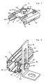
- Fig. 3 shows a perspective view of the special design of the holding element with the four angled web-shaped spacers 68 to 71, the opening 38 can be seen in the central web 34 of the holding claw 4. Furthermore shows this view well the downwardly or inwardly angled spring tongues 48, 51.
- the Approach 10 projects with the height 74 over the middle part 8. The height 74 is dependent given by the diameter of the approach 10, which is an integral part of the is a single piece of holding element.
- the spacers 68 to 71 are in the same from the central part 8 of the holding element Direction like the approach 10 and lie on the surface facing the profile of the component mentioned.
- the spacer elements 68 to 71 each have at least one a tooth or tip 76 which engages the surface of the component is brought and after tightening the screw mentioned a defined orientation of the component with respect to the holding element ultimately ensures the profile rail.
- the spacer elements 68 to 71 preferably contain several, in particular three such teeth or tips 76 to provide an anti-rotation device and a to ensure secure fixation and relative movements of the holding element as well exclude the profile rail with respect to the component for a long service life.
- the Teeth or tips 76 lead to changes in shape due to the high surface pressure the surface, with the result of a stable positive connection.
- the connecting element 10 designed as a cylindrical sleeve contains one L-shaped slot 75 in the manner of a bayonet catch.
- the slot 75 contains one axially parallel longitudinal part, through which a radial pin or cam of the is designed as a bolt fastener insertable. Is the fastener or the bolt mentioned so far that its pin the transverse Has reached part, the bolt for producing the bayonet connection becomes like this rotated that the cam or pin is locked in the transverse part of the slot 75.
- the said cross member can also be appropriately inclined so that a axial clamping of the holding element is achieved and the holding claws 4, 6 reinforced pressed and / or clamped into the associated lateral longitudinal grooves of the profile become.
- the bolt mentioned can if necessary according to the drawing at the top also have a thread for a nut, so that the component with the holding element to connect, expediently via the inclined surfaces or threaded surfaces of the bolt and the corresponding nut reaches the axial tension becomes.
- Fig. 4 shows the holding element for connecting the profile or the profile rail 60 with the component 78, which here as the connection angle of the profile 60 to a Wall or floor is formed.
- the component 78 contains the opening 62, which can be formed as a bore as well as a longitudinal slot. Through the breakthrough 62 engages the screw 80, which in the explained internal thread of the holding element is screwed in.
- the spacer elements 68, 71 protruding from the holding element rest on the surface 82 of the component 78.
- the profile rail 60 contains four Corner areas each have a longitudinal groove 84 to 87.
- the holding element engages with the holding claws 4, 6 in the two adjacent longitudinal grooves 86, 87 and is explained in the Way clamped on the rail 60.
Landscapes
- Engineering & Computer Science (AREA)
- General Engineering & Computer Science (AREA)
- Mechanical Engineering (AREA)
- Clamps And Clips (AREA)
- Mutual Connection Of Rods And Tubes (AREA)
- Finger-Pressure Massage (AREA)
- Joining Of Building Structures In Genera (AREA)
- Flanged Joints, Insulating Joints, And Other Joints (AREA)
- Surgical Instruments (AREA)
- Led Device Packages (AREA)
- Dowels (AREA)
- Non-Reversible Transmitting Devices (AREA)
- Registering, Tensioning, Guiding Webs, And Rollers Therefor (AREA)
- Semiconductor Lasers (AREA)
- Magnetic Heads (AREA)
- Supports For Pipes And Cables (AREA)
Applications Claiming Priority (4)
| Application Number | Priority Date | Filing Date | Title |
|---|---|---|---|
| DE19747887 | 1997-10-30 | ||
| DE1997147887 DE19747887C2 (de) | 1997-10-30 | 1997-10-30 | Halteelement |
| DE19749040A DE19749040A1 (de) | 1997-10-30 | 1997-11-06 | Halteelement |
| DE19749040 | 1997-11-06 |
Publications (3)
| Publication Number | Publication Date |
|---|---|
| EP0907032A2 EP0907032A2 (de) | 1999-04-07 |
| EP0907032A3 EP0907032A3 (de) | 1999-12-01 |
| EP0907032B1 true EP0907032B1 (de) | 2002-06-26 |
Family
ID=26041197
Family Applications (1)
| Application Number | Title | Priority Date | Filing Date |
|---|---|---|---|
| EP98118954A Expired - Lifetime EP0907032B1 (de) | 1997-10-30 | 1998-10-07 | Halteelement |
Country Status (11)
| Country | Link |
|---|---|
| EP (1) | EP0907032B1 (sk) |
| AT (1) | ATE219822T1 (sk) |
| CZ (1) | CZ292859B6 (sk) |
| DE (2) | DE19749040A1 (sk) |
| DK (1) | DK0907032T3 (sk) |
| ES (1) | ES2178089T3 (sk) |
| HR (1) | HRP980567A2 (sk) |
| NO (1) | NO985044L (sk) |
| PL (1) | PL329423A1 (sk) |
| SK (1) | SK145998A3 (sk) |
| YU (1) | YU48798A (sk) |
Families Citing this family (2)
| Publication number | Priority date | Publication date | Assignee | Title |
|---|---|---|---|---|
| ES2322787B1 (es) * | 2009-01-30 | 2010-07-07 | Schneider Electric España, S.A. | Dispositivo de union para bandejas de rejilla y tramo de bandejas de rejilla unidas mediante dicho dispositivo. |
| FR2976334B1 (fr) * | 2011-06-07 | 2015-06-19 | Legrand France | Accessoire d'angle pour chemins de cables en fils |
Family Cites Families (5)
| Publication number | Priority date | Publication date | Assignee | Title |
|---|---|---|---|---|
| US3486158A (en) * | 1967-09-29 | 1969-12-23 | Illinois Tool Works | Grounding clip |
| US4300865A (en) * | 1979-07-11 | 1981-11-17 | Trw Inc. | Blind clip fastener |
| FR2624932B1 (fr) * | 1987-12-22 | 1990-06-01 | Peugeot | Dispositif de montage d'un ecrou sur la face interne d'une piece |
| US5249900A (en) * | 1992-09-18 | 1993-10-05 | California Industrial Products, Inc. | Threaded fastener for mounting within an opening in a panel |
| DE4406208C2 (de) * | 1994-02-25 | 2001-10-11 | P & S Plan & Scan Ingenieur Gm | Anordnung mit einem Profilverbinder |
-
1997
- 1997-11-06 DE DE19749040A patent/DE19749040A1/de not_active Withdrawn
-
1998
- 1998-10-07 EP EP98118954A patent/EP0907032B1/de not_active Expired - Lifetime
- 1998-10-07 DK DK98118954T patent/DK0907032T3/da active
- 1998-10-07 AT AT98118954T patent/ATE219822T1/de not_active IP Right Cessation
- 1998-10-07 DE DE59804567T patent/DE59804567D1/de not_active Expired - Fee Related
- 1998-10-07 ES ES98118954T patent/ES2178089T3/es not_active Expired - Lifetime
- 1998-10-19 CZ CZ19983360A patent/CZ292859B6/cs not_active IP Right Cessation
- 1998-10-21 SK SK1459-98A patent/SK145998A3/sk unknown
- 1998-10-29 NO NO985044A patent/NO985044L/no not_active Application Discontinuation
- 1998-10-29 HR HR19749040.9A patent/HRP980567A2/hr not_active Application Discontinuation
- 1998-10-29 PL PL98329423A patent/PL329423A1/xx unknown
- 1998-10-30 YU YU48798A patent/YU48798A/sh unknown
Also Published As
| Publication number | Publication date |
|---|---|
| CZ292859B6 (cs) | 2003-12-17 |
| HRP980567A2 (en) | 1999-06-30 |
| NO985044D0 (no) | 1998-10-29 |
| DE59804567D1 (de) | 2002-08-01 |
| NO985044L (no) | 1999-05-03 |
| PL329423A1 (en) | 1999-05-10 |
| CZ336098A3 (cs) | 2000-07-12 |
| ATE219822T1 (de) | 2002-07-15 |
| EP0907032A2 (de) | 1999-04-07 |
| YU48798A (sh) | 2001-05-28 |
| DK0907032T3 (da) | 2002-09-30 |
| EP0907032A3 (de) | 1999-12-01 |
| SK145998A3 (en) | 2000-03-13 |
| DE19749040A1 (de) | 1999-08-05 |
| ES2178089T3 (es) | 2002-12-16 |
Similar Documents
| Publication | Publication Date | Title |
|---|---|---|
| EP0687822B2 (de) | Befestigungsvorrichtung | |
| DE2755674C2 (de) | Befestigungsvorrichtung | |
| EP1343974B2 (de) | Verbindereinrichtung für profile | |
| EP0528213A1 (de) | Beschlagteil zur Klemmbefestigung in einer mindestens einseitigen hinterschnittenen Profilnut | |
| EP1277971A1 (de) | Unverlierbarer Spreizanker | |
| EP0713018A1 (de) | Verbindungsanordnung | |
| EP1396644B1 (de) | Vorrichtung zum Verbinden von Montageschienen | |
| EP0907032B1 (de) | Halteelement | |
| DE19730269C2 (de) | Vorrichtung zum Befestigen eines ersten Teils mit einem zweiten Teil | |
| DE7918697U1 (de) | Verbindung von zwei koaxial hintereinander angeordneten Rohrabschnitten o.dgl | |
| DE19747887C2 (de) | Halteelement | |
| DE2735825C2 (sk) | ||
| DE19734601C2 (de) | Befestigungsvorrichtung | |
| EP1426632B1 (de) | Befestigungselement | |
| DE4016343C2 (sk) | ||
| DE3500423A1 (de) | Scharnier, insbesondere fuer moebel | |
| EP3763953B1 (de) | Mutter und rohrschelle mit dieser mutter | |
| DE3400146C2 (de) | Klammer zum Fixieren zweier über eine Aufnahmeöffnung ineinanderschiebbarer Bauteile | |
| WO2018153927A1 (de) | Befestigungsvorrichtung und befestigungsbaugruppe | |
| DE10107581B4 (de) | Vorrichtung zur Verbindung eines Kunststoffteils mit einem flachen Trägerteil | |
| EP3665395B1 (de) | Schelle zum befestigen eines rohr- oder schlauchförmigen gegenstands | |
| DE102006008111A1 (de) | Halteelement für Gitter | |
| DE10142438A1 (de) | Befestigungsanordnung | |
| DE102021133272A1 (de) | Verbindungsanordnung und Profilverbindungsanordnung | |
| DE102020214127A1 (de) | Vorrichtung zur Befestigung an einem Bauteil sowie ein Verfahren zur Befestigung einer Vorrichtung an einem Bauteil |
Legal Events
| Date | Code | Title | Description |
|---|---|---|---|
| PUAI | Public reference made under article 153(3) epc to a published international application that has entered the european phase |
Free format text: ORIGINAL CODE: 0009012 |
|
| AK | Designated contracting states |
Kind code of ref document: A2 Designated state(s): AT BE CH DE DK ES FI FR GB GR IT LI LU MC NL PT SE |
|
| AX | Request for extension of the european patent |
Free format text: AL;LT;LV;MK;RO PAYMENT 981007;SI PAYMENT 981007 |
|
| PUAL | Search report despatched |
Free format text: ORIGINAL CODE: 0009013 |
|
| AK | Designated contracting states |
Kind code of ref document: A3 Designated state(s): AT BE CH CY DE DK ES FI FR GB GR IE IT LI LU MC NL PT SE |
|
| AX | Request for extension of the european patent |
Free format text: AL;LT;LV;MK;RO PAYMENT 19981007;SI PAYMENT 19981007 |
|
| RIC1 | Information provided on ipc code assigned before grant |
Free format text: 6F 16B 7/04 A, 6F 16B 37/04 B, 6F 16B 37/02 B |
|
| 17P | Request for examination filed |
Effective date: 19991201 |
|
| AKX | Designation fees paid |
Free format text: AT BE CH DE DK ES FI FR GB GR IT LI LU MC NL PT SE |
|
| AXX | Extension fees paid |
Free format text: RO PAYMENT 19981007;SI PAYMENT 19981007 |
|
| 17Q | First examination report despatched |
Effective date: 20001208 |
|
| GRAG | Despatch of communication of intention to grant |
Free format text: ORIGINAL CODE: EPIDOS AGRA |
|
| GRAG | Despatch of communication of intention to grant |
Free format text: ORIGINAL CODE: EPIDOS AGRA |
|
| GRAH | Despatch of communication of intention to grant a patent |
Free format text: ORIGINAL CODE: EPIDOS IGRA |
|
| GRAH | Despatch of communication of intention to grant a patent |
Free format text: ORIGINAL CODE: EPIDOS IGRA |
|
| GRAA | (expected) grant |
Free format text: ORIGINAL CODE: 0009210 |
|
| AK | Designated contracting states |
Kind code of ref document: B1 Designated state(s): AT BE CH DE DK ES FI FR GB GR IT LI LU MC NL PT SE |
|
| AX | Request for extension of the european patent |
Free format text: RO PAYMENT 19981007;SI PAYMENT 19981007 |
|
| PG25 | Lapsed in a contracting state [announced via postgrant information from national office to epo] |
Ref country code: NL Free format text: LAPSE BECAUSE OF FAILURE TO SUBMIT A TRANSLATION OF THE DESCRIPTION OR TO PAY THE FEE WITHIN THE PRESCRIBED TIME-LIMIT Effective date: 20020626 Ref country code: GR Free format text: LAPSE BECAUSE OF FAILURE TO SUBMIT A TRANSLATION OF THE DESCRIPTION OR TO PAY THE FEE WITHIN THE PRESCRIBED TIME-LIMIT Effective date: 20020626 Ref country code: FR Free format text: LAPSE BECAUSE OF FAILURE TO SUBMIT A TRANSLATION OF THE DESCRIPTION OR TO PAY THE FEE WITHIN THE PRESCRIBED TIME-LIMIT Effective date: 20020626 Ref country code: FI Free format text: LAPSE BECAUSE OF FAILURE TO SUBMIT A TRANSLATION OF THE DESCRIPTION OR TO PAY THE FEE WITHIN THE PRESCRIBED TIME-LIMIT Effective date: 20020626 |
|
| REF | Corresponds to: |
Ref document number: 219822 Country of ref document: AT Date of ref document: 20020715 Kind code of ref document: T |
|
| REG | Reference to a national code |
Ref country code: GB Ref legal event code: FG4D Free format text: NOT ENGLISH |
|
| REG | Reference to a national code |
Ref country code: CH Ref legal event code: EP |
|
| REF | Corresponds to: |
Ref document number: 59804567 Country of ref document: DE Date of ref document: 20020801 |
|
| PG25 | Lapsed in a contracting state [announced via postgrant information from national office to epo] |
Ref country code: PT Free format text: LAPSE BECAUSE OF FAILURE TO SUBMIT A TRANSLATION OF THE DESCRIPTION OR TO PAY THE FEE WITHIN THE PRESCRIBED TIME-LIMIT Effective date: 20020926 |
|
| REG | Reference to a national code |
Ref country code: DK Ref legal event code: T3 |
|
| PG25 | Lapsed in a contracting state [announced via postgrant information from national office to epo] |
Ref country code: LU Free format text: LAPSE BECAUSE OF NON-PAYMENT OF DUE FEES Effective date: 20021007 |
|
| GBT | Gb: translation of ep patent filed (gb section 77(6)(a)/1977) |
Effective date: 20020919 |
|
| NLV1 | Nl: lapsed or annulled due to failure to fulfill the requirements of art. 29p and 29m of the patents act | ||
| REG | Reference to a national code |
Ref country code: ES Ref legal event code: FG2A Ref document number: 2178089 Country of ref document: ES Kind code of ref document: T3 |
|
| EN | Fr: translation not filed | ||
| PG25 | Lapsed in a contracting state [announced via postgrant information from national office to epo] |
Ref country code: MC Free format text: LAPSE BECAUSE OF NON-PAYMENT OF DUE FEES Effective date: 20030501 |
|
| PLBE | No opposition filed within time limit |
Free format text: ORIGINAL CODE: 0009261 |
|
| STAA | Information on the status of an ep patent application or granted ep patent |
Free format text: STATUS: NO OPPOSITION FILED WITHIN TIME LIMIT |
|
| 26N | No opposition filed |
Effective date: 20030327 |
|
| PGFP | Annual fee paid to national office [announced via postgrant information from national office to epo] |
Ref country code: GB Payment date: 20030915 Year of fee payment: 6 |
|
| PGFP | Annual fee paid to national office [announced via postgrant information from national office to epo] |
Ref country code: BE Payment date: 20031024 Year of fee payment: 6 Ref country code: AT Payment date: 20031024 Year of fee payment: 6 |
|
| PGFP | Annual fee paid to national office [announced via postgrant information from national office to epo] |
Ref country code: SE Payment date: 20031027 Year of fee payment: 6 Ref country code: CH Payment date: 20031027 Year of fee payment: 6 |
|
| PGFP | Annual fee paid to national office [announced via postgrant information from national office to epo] |
Ref country code: ES Payment date: 20031029 Year of fee payment: 6 Ref country code: DK Payment date: 20031029 Year of fee payment: 6 |
|
| PGFP | Annual fee paid to national office [announced via postgrant information from national office to epo] |
Ref country code: DE Payment date: 20031031 Year of fee payment: 6 |
|
| PG25 | Lapsed in a contracting state [announced via postgrant information from national office to epo] |
Ref country code: DE Free format text: LAPSE BECAUSE OF NON-PAYMENT OF DUE FEES Effective date: 20040501 |
|
| PG25 | Lapsed in a contracting state [announced via postgrant information from national office to epo] |
Ref country code: GB Free format text: LAPSE BECAUSE OF NON-PAYMENT OF DUE FEES Effective date: 20041007 Ref country code: AT Free format text: LAPSE BECAUSE OF NON-PAYMENT OF DUE FEES Effective date: 20041007 |
|
| PG25 | Lapsed in a contracting state [announced via postgrant information from national office to epo] |
Ref country code: SE Free format text: LAPSE BECAUSE OF NON-PAYMENT OF DUE FEES Effective date: 20041008 Ref country code: ES Free format text: LAPSE BECAUSE OF NON-PAYMENT OF DUE FEES Effective date: 20041008 |
|
| PG25 | Lapsed in a contracting state [announced via postgrant information from national office to epo] |
Ref country code: LI Free format text: LAPSE BECAUSE OF NON-PAYMENT OF DUE FEES Effective date: 20041031 Ref country code: CH Free format text: LAPSE BECAUSE OF NON-PAYMENT OF DUE FEES Effective date: 20041031 Ref country code: BE Free format text: LAPSE BECAUSE OF NON-PAYMENT OF DUE FEES Effective date: 20041031 |
|
| PG25 | Lapsed in a contracting state [announced via postgrant information from national office to epo] |
Ref country code: DK Free format text: LAPSE BECAUSE OF NON-PAYMENT OF DUE FEES Effective date: 20041101 |
|
| BERE | Be: lapsed |
Owner name: *FRIATEC A.G. Effective date: 20041031 |
|
| GBPC | Gb: european patent ceased through non-payment of renewal fee |
Effective date: 20041007 |
|
| EUG | Se: european patent has lapsed | ||
| REG | Reference to a national code |
Ref country code: DK Ref legal event code: EBP |
|
| REG | Reference to a national code |
Ref country code: CH Ref legal event code: PL |
|
| PG25 | Lapsed in a contracting state [announced via postgrant information from national office to epo] |
Ref country code: IT Free format text: LAPSE BECAUSE OF NON-PAYMENT OF DUE FEES Effective date: 20051007 |
|
| REG | Reference to a national code |
Ref country code: ES Ref legal event code: FD2A Effective date: 20041008 |
|
| BERE | Be: lapsed |
Owner name: *FRIATEC A.G. Effective date: 20041031 |