EP0907031A2 - Dispositif de commande d'un vérin hydraulique d'une moissonneuse automotrice - Google Patents
Dispositif de commande d'un vérin hydraulique d'une moissonneuse automotrice Download PDFInfo
- Publication number
- EP0907031A2 EP0907031A2 EP98115143A EP98115143A EP0907031A2 EP 0907031 A2 EP0907031 A2 EP 0907031A2 EP 98115143 A EP98115143 A EP 98115143A EP 98115143 A EP98115143 A EP 98115143A EP 0907031 A2 EP0907031 A2 EP 0907031A2
- Authority
- EP
- European Patent Office
- Prior art keywords
- pump
- hydraulic cylinder
- valve
- variable displacement
- control unit
- Prior art date
- Legal status (The legal status is an assumption and is not a legal conclusion. Google has not performed a legal analysis and makes no representation as to the accuracy of the status listed.)
- Granted
Links
- 239000012530 fluid Substances 0.000 claims abstract description 5
- 238000006073 displacement reaction Methods 0.000 claims description 24
- 230000001419 dependent effect Effects 0.000 claims description 7
- 238000005086 pumping Methods 0.000 claims description 2
- 241001124569 Lycaenidae Species 0.000 description 2
- 238000010586 diagram Methods 0.000 description 2
- 238000011144 upstream manufacturing Methods 0.000 description 2
- 230000000694 effects Effects 0.000 description 1
Images

Classifications
-
- F—MECHANICAL ENGINEERING; LIGHTING; HEATING; WEAPONS; BLASTING
- F15—FLUID-PRESSURE ACTUATORS; HYDRAULICS OR PNEUMATICS IN GENERAL
- F15B—SYSTEMS ACTING BY MEANS OF FLUIDS IN GENERAL; FLUID-PRESSURE ACTUATORS, e.g. SERVOMOTORS; DETAILS OF FLUID-PRESSURE SYSTEMS, NOT OTHERWISE PROVIDED FOR
- F15B11/00—Servomotor systems without provision for follow-up action; Circuits therefor
- F15B11/16—Servomotor systems without provision for follow-up action; Circuits therefor with two or more servomotors
-
- F—MECHANICAL ENGINEERING; LIGHTING; HEATING; WEAPONS; BLASTING
- F15—FLUID-PRESSURE ACTUATORS; HYDRAULICS OR PNEUMATICS IN GENERAL
- F15B—SYSTEMS ACTING BY MEANS OF FLUIDS IN GENERAL; FLUID-PRESSURE ACTUATORS, e.g. SERVOMOTORS; DETAILS OF FLUID-PRESSURE SYSTEMS, NOT OTHERWISE PROVIDED FOR
- F15B21/00—Common features of fluid actuator systems; Fluid-pressure actuator systems or details thereof, not covered by any other group of this subclass
- F15B21/08—Servomotor systems incorporating electrically operated control means
- F15B21/087—Control strategy, e.g. with block diagram
-
- F—MECHANICAL ENGINEERING; LIGHTING; HEATING; WEAPONS; BLASTING
- F15—FLUID-PRESSURE ACTUATORS; HYDRAULICS OR PNEUMATICS IN GENERAL
- F15B—SYSTEMS ACTING BY MEANS OF FLUIDS IN GENERAL; FLUID-PRESSURE ACTUATORS, e.g. SERVOMOTORS; DETAILS OF FLUID-PRESSURE SYSTEMS, NOT OTHERWISE PROVIDED FOR
- F15B2211/00—Circuits for servomotor systems
- F15B2211/20—Fluid pressure source, e.g. accumulator or variable axial piston pump
- F15B2211/205—Systems with pumps
- F15B2211/2053—Type of pump
- F15B2211/20546—Type of pump variable capacity
-
- F—MECHANICAL ENGINEERING; LIGHTING; HEATING; WEAPONS; BLASTING
- F15—FLUID-PRESSURE ACTUATORS; HYDRAULICS OR PNEUMATICS IN GENERAL
- F15B—SYSTEMS ACTING BY MEANS OF FLUIDS IN GENERAL; FLUID-PRESSURE ACTUATORS, e.g. SERVOMOTORS; DETAILS OF FLUID-PRESSURE SYSTEMS, NOT OTHERWISE PROVIDED FOR
- F15B2211/00—Circuits for servomotor systems
- F15B2211/40—Flow control
- F15B2211/405—Flow control characterised by the type of flow control means or valve
- F15B2211/40507—Flow control characterised by the type of flow control means or valve with constant throttles or orifices
-
- F—MECHANICAL ENGINEERING; LIGHTING; HEATING; WEAPONS; BLASTING
- F15—FLUID-PRESSURE ACTUATORS; HYDRAULICS OR PNEUMATICS IN GENERAL
- F15B—SYSTEMS ACTING BY MEANS OF FLUIDS IN GENERAL; FLUID-PRESSURE ACTUATORS, e.g. SERVOMOTORS; DETAILS OF FLUID-PRESSURE SYSTEMS, NOT OTHERWISE PROVIDED FOR
- F15B2211/00—Circuits for servomotor systems
- F15B2211/40—Flow control
- F15B2211/415—Flow control characterised by the connections of the flow control means in the circuit
- F15B2211/41509—Flow control characterised by the connections of the flow control means in the circuit being connected to a pressure source and a directional control valve
-
- F—MECHANICAL ENGINEERING; LIGHTING; HEATING; WEAPONS; BLASTING
- F15—FLUID-PRESSURE ACTUATORS; HYDRAULICS OR PNEUMATICS IN GENERAL
- F15B—SYSTEMS ACTING BY MEANS OF FLUIDS IN GENERAL; FLUID-PRESSURE ACTUATORS, e.g. SERVOMOTORS; DETAILS OF FLUID-PRESSURE SYSTEMS, NOT OTHERWISE PROVIDED FOR
- F15B2211/00—Circuits for servomotor systems
- F15B2211/40—Flow control
- F15B2211/45—Control of bleed-off flow, e.g. control of bypass flow to the return line
-
- F—MECHANICAL ENGINEERING; LIGHTING; HEATING; WEAPONS; BLASTING
- F15—FLUID-PRESSURE ACTUATORS; HYDRAULICS OR PNEUMATICS IN GENERAL
- F15B—SYSTEMS ACTING BY MEANS OF FLUIDS IN GENERAL; FLUID-PRESSURE ACTUATORS, e.g. SERVOMOTORS; DETAILS OF FLUID-PRESSURE SYSTEMS, NOT OTHERWISE PROVIDED FOR
- F15B2211/00—Circuits for servomotor systems
- F15B2211/40—Flow control
- F15B2211/455—Control of flow in the feed line, i.e. meter-in control
-
- F—MECHANICAL ENGINEERING; LIGHTING; HEATING; WEAPONS; BLASTING
- F15—FLUID-PRESSURE ACTUATORS; HYDRAULICS OR PNEUMATICS IN GENERAL
- F15B—SYSTEMS ACTING BY MEANS OF FLUIDS IN GENERAL; FLUID-PRESSURE ACTUATORS, e.g. SERVOMOTORS; DETAILS OF FLUID-PRESSURE SYSTEMS, NOT OTHERWISE PROVIDED FOR
- F15B2211/00—Circuits for servomotor systems
- F15B2211/60—Circuit components or control therefor
- F15B2211/63—Electronic controllers
- F15B2211/6303—Electronic controllers using input signals
-
- F—MECHANICAL ENGINEERING; LIGHTING; HEATING; WEAPONS; BLASTING
- F15—FLUID-PRESSURE ACTUATORS; HYDRAULICS OR PNEUMATICS IN GENERAL
- F15B—SYSTEMS ACTING BY MEANS OF FLUIDS IN GENERAL; FLUID-PRESSURE ACTUATORS, e.g. SERVOMOTORS; DETAILS OF FLUID-PRESSURE SYSTEMS, NOT OTHERWISE PROVIDED FOR
- F15B2211/00—Circuits for servomotor systems
- F15B2211/60—Circuit components or control therefor
- F15B2211/665—Methods of control using electronic components
- F15B2211/6652—Control of the pressure source, e.g. control of the swash plate angle
-
- F—MECHANICAL ENGINEERING; LIGHTING; HEATING; WEAPONS; BLASTING
- F15—FLUID-PRESSURE ACTUATORS; HYDRAULICS OR PNEUMATICS IN GENERAL
- F15B—SYSTEMS ACTING BY MEANS OF FLUIDS IN GENERAL; FLUID-PRESSURE ACTUATORS, e.g. SERVOMOTORS; DETAILS OF FLUID-PRESSURE SYSTEMS, NOT OTHERWISE PROVIDED FOR
- F15B2211/00—Circuits for servomotor systems
- F15B2211/70—Output members, e.g. hydraulic motors or cylinders or control therefor
- F15B2211/71—Multiple output members, e.g. multiple hydraulic motors or cylinders
- F15B2211/7142—Multiple output members, e.g. multiple hydraulic motors or cylinders the output members being arranged in multiple groups
-
- F—MECHANICAL ENGINEERING; LIGHTING; HEATING; WEAPONS; BLASTING
- F15—FLUID-PRESSURE ACTUATORS; HYDRAULICS OR PNEUMATICS IN GENERAL
- F15B—SYSTEMS ACTING BY MEANS OF FLUIDS IN GENERAL; FLUID-PRESSURE ACTUATORS, e.g. SERVOMOTORS; DETAILS OF FLUID-PRESSURE SYSTEMS, NOT OTHERWISE PROVIDED FOR
- F15B2211/00—Circuits for servomotor systems
- F15B2211/70—Output members, e.g. hydraulic motors or cylinders or control therefor
- F15B2211/78—Control of multiple output members
Definitions
- the invention relates to a device for controlling a Hydraulic cylinders in a self-propelled harvester with a variable displacement pump for pumping a hydraulic fluid and with at least one associated with the hydraulic cylinder Valve.
- a hydraulic control circuit For actuating hydraulic cylinders, for example a header of a harvester or a conveyor of the same a hydraulic control circuit is known, which has variable pumps and proportional directional valves and depending on the particular need one with the Hydraulic cylinder connected consumer a corresponding Funding volume.
- the object of the invention is therefore to provide a device for Control of a hydraulic cylinder in a self-propelled Harvester specify which is a simple, inexpensive and effective control of hydraulic cylinders guaranteed.
- the invention is characterized in that that the valve is designed as a switching valve and that the switching valve and the variable displacement pump are so electric can be controlled that that supplied by the variable displacement pump Delivery volume to the requirements of the hydraulic cylinder is adjusted.
- the particular advantage of the invention is that the required quickly and to a sufficient extent on request Delivery volume for actuating the hydraulic cylinder can be provided. This is made possible through the combination of a fast-switching switching valve and a variable displacement pump, each of which can be operated electrically are.
- variable displacement pump on the one hand and the switching valve on the other hand with a electrical control unit connected, the means for Generation of control signals depending on a predetermined Has actuation signal.
- the electrical control unit enables the need-based control of the Variable pump, so that a consumer-dependent control of the correspondingly assigned hydraulic cylinder is effected.
- the electrical Control unit a pump control signal, which is a stepless Setting the delivery volume supplied by the variable pump enables. This can make the different Speed and length requirements of the stroke are taken into account.
- the electrical Control unit means for storing control curves for several hydraulic cylinders so that hydraulic cylinders are automatically operated in the specified order can.
- the switching valves upstream of each a current valve by means of which the flow to the respective hydraulic cylinders can be adjusted.
- a flow valve is preferred designed as a 3-way flow control valve that one is assigned to the first hydraulic cylinder, with a constant Volume flow branched off to further hydraulic cylinders becomes.
- the device according to the invention can be used to actuate Used by self-propelled harvesters become. For example, a header in moved vertically or around a horizontal axis be pivoted. Furthermore, the device for actuation a swiveling grain tank outlet pipe, conveyor or feeder for the crop or for the Swiveling a cultivator used as a consumer become.
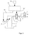
- a variable displacement pump 2 is intended to convey a hydraulic fluid in a Delivery line 3 from a tank 4 to a switching valve 5.
- the switching valve 5 is by means of another delivery line 6 connected to a connection of the hydraulic cylinder 1.
- One on the opposite side of the hydraulic cylinder 1 connected drain line 7 carries the hydraulic fluid pressureless back via the switching valve 5 the tank 4.
- the hydraulic cylinder 1 has a piston rod 8 with a on the same piston 9 connected at the end, which is movable are stored in the hydraulic cylinder 1.
- a free one The end of the piston rod 8 extends outside the hydraulic cylinder 1 and is with a not shown Connected consumers.
- the variable displacement pump 2 is designed as an axial piston pump and is electrically operated.
- the variable displacement pump is for this purpose 2 through an electrical line 10 with a electrical control unit 11 electrically connected.
- the Switch valve 5 is designed as a 4/3-way valve and is electromagnetic actuatable.
- the switching valve 5 an electrical connecting line 12 to the electrical control unit 11.
- the control unit 11 is electrically connected on the input side to a key element 13, preferably in a cab of the harvester is arranged.
- a consumer connected to the hydraulic cylinder 1 in a predetermined position By pressing the button element 13, for example a consumer connected to the hydraulic cylinder 1 in a predetermined position can be pivoted.
- the key element 13 gives an actuation signal to the control unit 11, the means for generating a pump control signal on the one hand and for generating a valve control signal on the other hand.
- the pump control signal is via the electrical line 10 to the variable displacement pump 2 transmitted, the size of the pump control signal to one consumer-dependent volume flow corresponds.
- the the switching valve via the electrical connecting line 12 5 Actuating valve control signal switches valve 5 such that the piston 9 moves in a predetermined direction becomes.
- control unit 11 can also be used for control purposes serve several variable pumps 2 or switching valves 5, wherein consumer-dependent data of the respective variable pumps 2 and valves 5 are assigned.
- electrical control unit 11 an integrated circuit on.
- an electrical control unit 15 is provided for the control a variable displacement pump 16 and several switching valves 17, 17 ', 17' 'is used.
- the control unit 15 via a control line 18 with the variable displacement pump 16 and Control lines 19, 19 ', 19' 'with the switching valves 17, 17 ', 17' 'connected.
- the variable displacement pump 16 is on the pressure side connected to a 3-way flow control valve 20, the first Output via the switching valve 17 with a first hydraulic cylinder 21 is connected.
- a second exit of the 3-way flow control valve 20 is each via a 2-way flow control valve 22, 22 'and corresponding switching valves 17 ', 17' 'with a second hydraulic cylinder 21' or a third hydraulic cylinder 21 ''.
- the 3-way flow control valve 20 is designed such that a constant Volume flow in the direction of the two hydraulic cylinders 21 ', 21' 'is branched, the 2-way flow control valves 22, 22 'have an even distribution Hydraulic cylinder 21 ', 21' 'effect.
- the control unit 15 is in each case with a Key element 23, a lever element 24 and a multi-function handle 25 connected as input elements.
- These input elements 23, 24, 25 are each a hydraulic cylinder 21, 21 ', 21' 'assigned.
- Pump control signal such a level that a needs-based Volume flow is generated by means of a valve control signal the control unit 15 addressed Switching valve 17 to the hydraulic cylinder 21 is promoted.
- all input elements 23, 24, 25 is a correspondingly higher pump control signal to the Variable pump 16 delivered.
- the 3-way flow control valve 20 guaranteed in connection with the 2-way flow control valves 22, 22 ' an even distribution of the volume flow to the hydraulic cylinders 21, 21 ', 21' '.
- a sensor 26 with the electrical control unit 15 be electrically connected, so that depending a specific hydraulic cylinder from a sensor signal 21, 21 ', 21' 'is addressed.
- the contour of the ground is detected by means of the sensor 26 be, a corresponding in the control unit 15 long pump control signal of a certain height and a corresponding one Valve assigned control signal generated is, so that the assigned according to the cutting unit Hydraulic cylinders ensure a certain cutting height can.
- the control unit 15 has a microcontroller 28 on, in which the arithmetic operations for generation of the control signals are carried out. Farther can in a memory of the microcontroller 28 consumer-dependent Control data must be stored when there is a change or extension of the consumers to be operated can be.
- the senor 26 can be used together with the multifunction handle 25 to a first hydraulic cylinder 21 Act.
- the sensor signal causes a presetting the cutting unit if there is an uneven floor.
- the sensor 26 is used in cooperation with the control unit 15 as an actuator, while later or at the same time an exact setting of the consumer is done manually. That way, faster to be reacted to external interference, the operator is relieved in its concentration.
- the multi-function handle 25 with the control unit 15 be connected such that by pressing one Button 30 of the multi-function handle 25 a the hydraulic cylinder 21 controlling pump control signal is given, meanwhile by additionally pivoting the handle 29 the speed of movement of the piston 9 of the Hydraulic cylinder 21 is affected. For example by moving the handle 29 from a zero position forward an increased speed of the piston in a first direction and by moving the handle 29 after rear increased piston speed into one opposite direction. To this end becomes dependent on the control signal of the multifunction handle 25 a corresponding pump control signal to the Pump that is continuously adjustable and a correspondingly adjusted volume flow generated.
- circuitry linking the Variable pump 2 on the one hand with the Sachlt valve 5 on the other is that noises due to movements of the Hydraulic lines 3, 6, 7 or more in the case of strong pressure fluctuations largely avoided in the hydraulic circuit become.
- the invention is not based on the specified number of hydraulic cylinders limited. Of course it can other consumers connected to the hydraulic circuit be, with appropriate flow control valves upstream are.
- variable displacement pump 2 can be replaced by a ramp-shaped one Pump control signal can be controlled, with a predetermined The piston stroke of the variable displacement pump 2 is fixed becomes.
- the piston of the variable displacement pump 2 is here after a certain characteristic in one direction and then again moved in the opposite direction. After that you can the corresponding switching valve can be switched off.
Landscapes
- Engineering & Computer Science (AREA)
- Physics & Mathematics (AREA)
- Fluid Mechanics (AREA)
- Mechanical Engineering (AREA)
- General Engineering & Computer Science (AREA)
- Chemical & Material Sciences (AREA)
- Analytical Chemistry (AREA)
- Fluid-Pressure Circuits (AREA)
- Control Of Positive-Displacement Pumps (AREA)
- Lifting Devices For Agricultural Implements (AREA)
Applications Claiming Priority (2)
| Application Number | Priority Date | Filing Date | Title |
|---|---|---|---|
| DE1997143801 DE19743801A1 (de) | 1997-10-02 | 1997-10-02 | Vorrichtung zur Steuerung eines Hydraulikzylinders in einer selbstfahrenden Erntemaschine |
| DE19743801 | 1997-10-02 |
Publications (3)
| Publication Number | Publication Date |
|---|---|
| EP0907031A2 true EP0907031A2 (fr) | 1999-04-07 |
| EP0907031A3 EP0907031A3 (fr) | 2001-01-10 |
| EP0907031B1 EP0907031B1 (fr) | 2011-01-05 |
Family
ID=7844534
Family Applications (1)
| Application Number | Title | Priority Date | Filing Date |
|---|---|---|---|
| EP19980115143 Expired - Lifetime EP0907031B1 (fr) | 1997-10-02 | 1998-08-12 | Dispositif de commande d'un vérin hydraulique d'une moissonneuse automotrice |
Country Status (2)
| Country | Link |
|---|---|
| EP (1) | EP0907031B1 (fr) |
| DE (2) | DE19743801A1 (fr) |
Cited By (1)
| Publication number | Priority date | Publication date | Assignee | Title |
|---|---|---|---|---|
| EP2255945A1 (fr) * | 2009-05-05 | 2010-12-01 | KraussMaffei Technologies GmbH | Dispositif d'entraînement hydroélectrique comme agrégat auxiliaire pour une machine de moulage par injection |
Citations (1)
| Publication number | Priority date | Publication date | Assignee | Title |
|---|---|---|---|---|
| WO1997002432A1 (fr) | 1995-07-05 | 1997-01-23 | Caterpillar Inc. | Systeme de commande d'un verin hydraulique et procede |
Family Cites Families (10)
| Publication number | Priority date | Publication date | Assignee | Title |
|---|---|---|---|---|
| DE2902264A1 (de) * | 1979-01-22 | 1980-07-24 | Bosch Gmbh Robert | Steuereinrichtung fuer eine hydraulikanlage |
| DE2904293A1 (de) * | 1979-02-05 | 1980-08-07 | Claas Ohg | Hydraulisches steuerventil |
| DE3546336A1 (de) * | 1985-12-30 | 1987-07-02 | Rexroth Mannesmann Gmbh | Steueranordnung fuer mindestens zwei von mindestens einer pumpe gespeiste hydraulische verbraucher |
| KR950007624B1 (ko) * | 1990-09-28 | 1995-07-13 | 히다찌 겐끼 가부시기가이샤 | 유압펌프의 제어장치 |
| DE59105057D1 (de) * | 1990-12-15 | 1995-05-04 | Barmag Barmer Maschf | Hydrauliksystem. |
| US5261234A (en) * | 1992-01-07 | 1993-11-16 | Caterpillar Inc. | Hydraulic control apparatus |
| US5249421A (en) * | 1992-01-13 | 1993-10-05 | Caterpillar Inc. | Hydraulic control apparatus with mode selection |
| JPH05256303A (ja) * | 1992-01-15 | 1993-10-05 | Caterpillar Inc | 油圧回路制御装置 |
| DE4235380C2 (de) * | 1992-06-19 | 1995-05-11 | Weimar Werk Maschinenbau Gmbh | Anordnung zur Steuerung von Erntemaschinen |
| US5383390A (en) * | 1993-06-28 | 1995-01-24 | Caterpillar Inc. | Multi-variable control of multi-degree of freedom linkages |
-
1997
- 1997-10-02 DE DE1997143801 patent/DE19743801A1/de not_active Withdrawn
-
1998
- 1998-08-12 EP EP19980115143 patent/EP0907031B1/fr not_active Expired - Lifetime
- 1998-08-12 DE DE59814480T patent/DE59814480D1/de not_active Expired - Lifetime
Patent Citations (1)
| Publication number | Priority date | Publication date | Assignee | Title |
|---|---|---|---|---|
| WO1997002432A1 (fr) | 1995-07-05 | 1997-01-23 | Caterpillar Inc. | Systeme de commande d'un verin hydraulique et procede |
Cited By (1)
| Publication number | Priority date | Publication date | Assignee | Title |
|---|---|---|---|---|
| EP2255945A1 (fr) * | 2009-05-05 | 2010-12-01 | KraussMaffei Technologies GmbH | Dispositif d'entraînement hydroélectrique comme agrégat auxiliaire pour une machine de moulage par injection |
Also Published As
| Publication number | Publication date |
|---|---|
| EP0907031A3 (fr) | 2001-01-10 |
| DE59814480D1 (de) | 2011-02-17 |
| EP0907031B1 (fr) | 2011-01-05 |
| DE19743801A1 (de) | 1999-04-08 |
Similar Documents
| Publication | Publication Date | Title |
|---|---|---|
| DE69808889T2 (de) | Düsenanordnung | |
| DE2508620A1 (de) | Regelsystem fuer einen traktor | |
| DE19539143A1 (de) | Einzugsvorrichtung für Feldhäcksler | |
| EP0628236B1 (fr) | Dispositif réglable en hauteur | |
| DE10000110B4 (de) | Hydrostatischer Fahrzeugantrieb mit Steuerungseinrichtung und Steuerungseinrichtung für hydrostatische Antriebe | |
| DE19718579B4 (de) | Steuerung zur Regelung der Preßkraft einer Großballenpresse | |
| DE3910120A1 (de) | Steuerungsanordnung fuer eine zweizylinder-dickstoffpumpe | |
| DE2025040A1 (de) | Laengenveraenderlicher Oberlenker fuer eine Dreipunkt-Anhaengevorrichtung | |
| EP0070015B1 (fr) | Commande automatique de position pour le réglage de l'angle relatif entre le tuyau de décharge d'une moissonneuse et la remorque attelée recevant le produit récolté | |
| DE3225076A1 (de) | Vorrichtung zum zumischen von desinfektionsmittel zu wasser | |
| EP0907031B1 (fr) | Dispositif de commande d'un vérin hydraulique d'une moissonneuse automotrice | |
| DE102005025966A1 (de) | Lenksystem für landwirtschaftliche Fahrzeuge | |
| DE3438353A1 (de) | Hydraulische einrichtung fuer ein landwirtschaftliches arbeitsfahrzeug, insbesondere traktor | |
| DE2751449B1 (de) | Vorrichtung zur Lage- und/oder Arbeitstiefenregelung an landwirtschaftlichen Maschinen,insbesondere fuer mit Ackerschleppern gekuppelte Anbaugeraete | |
| DE3214206A1 (de) | Ackerschlepper mit einer heck- und frontseitigen geraeteanbauvorrichtung | |
| EP3485728B1 (fr) | Machine d'épandage agricole | |
| EP0223224B1 (fr) | Pulvérisateur agricole pour cultures de plein champ | |
| DE69222843T2 (de) | Eingangsglied | |
| DE1757614A1 (de) | Bodenbearbeitungsgeraet mit hydraulisch einschwenkbarem Werkzeug | |
| DE69928593T2 (de) | Elektronisches Steuersystem | |
| DE19542371A1 (de) | Wegeventilblock | |
| DE2025114A1 (de) | Strömungsmittelgerät, insbesondere zum Betätigen von Ventilen, Schaltern, Motoren und ähnlichem | |
| DE1780079C2 (de) | Lenkvorrichtung für Landmaschinen, insbesondere selbstfahrende Mähdrescher | |
| EP4420500A1 (fr) | Agencement hydraulique pour alimenter un outil avec puissance hydraulique | |
| DE9400234U1 (de) | Straßenmarkierungsmaschine mit Drosselvorrichtung zur Beeinflussung des Markierungsstoffauftrages |
Legal Events
| Date | Code | Title | Description |
|---|---|---|---|
| PUAI | Public reference made under article 153(3) epc to a published international application that has entered the european phase |
Free format text: ORIGINAL CODE: 0009012 |
|
| AK | Designated contracting states |
Kind code of ref document: A2 Designated state(s): BE DE DK FR GB IT |
|
| AX | Request for extension of the european patent |
Free format text: AL;LT;LV;MK;RO;SI |
|
| PUAL | Search report despatched |
Free format text: ORIGINAL CODE: 0009013 |
|
| AK | Designated contracting states |
Kind code of ref document: A3 Designated state(s): AT BE CH CY DE DK ES FI FR GB GR IE IT LI LU MC NL PT SE |
|
| AX | Request for extension of the european patent |
Free format text: AL;LT;LV;MK;RO;SI |
|
| RIC1 | Information provided on ipc code assigned before grant |
Free format text: 7F 15B 21/08 A, 7F 15B 11/16 B |
|
| 17P | Request for examination filed |
Effective date: 20010710 |
|
| AKX | Designation fees paid |
Free format text: BE DE DK FR GB IT |
|
| 17Q | First examination report despatched |
Effective date: 20040924 |
|
| GRAP | Despatch of communication of intention to grant a patent |
Free format text: ORIGINAL CODE: EPIDOSNIGR1 |
|
| GRAS | Grant fee paid |
Free format text: ORIGINAL CODE: EPIDOSNIGR3 |
|
| GRAA | (expected) grant |
Free format text: ORIGINAL CODE: 0009210 |
|
| AK | Designated contracting states |
Kind code of ref document: B1 Designated state(s): BE DE DK FR GB IT |
|
| REG | Reference to a national code |
Ref country code: GB Ref legal event code: FG4D Free format text: NOT ENGLISH |
|
| REF | Corresponds to: |
Ref document number: 59814480 Country of ref document: DE Date of ref document: 20110217 Kind code of ref document: P |
|
| REG | Reference to a national code |
Ref country code: DE Ref legal event code: R096 Ref document number: 59814480 Country of ref document: DE Effective date: 20110217 |
|
| PG25 | Lapsed in a contracting state [announced via postgrant information from national office to epo] |
Ref country code: DK Free format text: LAPSE BECAUSE OF FAILURE TO SUBMIT A TRANSLATION OF THE DESCRIPTION OR TO PAY THE FEE WITHIN THE PRESCRIBED TIME-LIMIT Effective date: 20110105 |
|
| PLBE | No opposition filed within time limit |
Free format text: ORIGINAL CODE: 0009261 |
|
| STAA | Information on the status of an ep patent application or granted ep patent |
Free format text: STATUS: NO OPPOSITION FILED WITHIN TIME LIMIT |
|
| 26N | No opposition filed |
Effective date: 20111006 |
|
| REG | Reference to a national code |
Ref country code: DE Ref legal event code: R097 Ref document number: 59814480 Country of ref document: DE Effective date: 20111006 |
|
| GBPC | Gb: european patent ceased through non-payment of renewal fee |
Effective date: 20110812 |
|
| REG | Reference to a national code |
Ref country code: FR Ref legal event code: ST Effective date: 20120430 |
|
| PG25 | Lapsed in a contracting state [announced via postgrant information from national office to epo] |
Ref country code: IT Free format text: LAPSE BECAUSE OF NON-PAYMENT OF DUE FEES Effective date: 20110812 |
|
| REG | Reference to a national code |
Ref country code: DE Ref legal event code: R084 Ref document number: 59814480 Country of ref document: DE Effective date: 20120623 |
|
| PG25 | Lapsed in a contracting state [announced via postgrant information from national office to epo] |
Ref country code: GB Free format text: LAPSE BECAUSE OF NON-PAYMENT OF DUE FEES Effective date: 20110812 Ref country code: FR Free format text: LAPSE BECAUSE OF NON-PAYMENT OF DUE FEES Effective date: 20110831 |
|
| PGFP | Annual fee paid to national office [announced via postgrant information from national office to epo] |
Ref country code: DE Payment date: 20130703 Year of fee payment: 16 |
|
| PGFP | Annual fee paid to national office [announced via postgrant information from national office to epo] |
Ref country code: BE Payment date: 20130823 Year of fee payment: 16 |
|
| REG | Reference to a national code |
Ref country code: DE Ref legal event code: R119 Ref document number: 59814480 Country of ref document: DE |
|
| PG25 | Lapsed in a contracting state [announced via postgrant information from national office to epo] |
Ref country code: BE Free format text: LAPSE BECAUSE OF NON-PAYMENT OF DUE FEES Effective date: 20140831 |
|
| REG | Reference to a national code |
Ref country code: DE Ref legal event code: R119 Ref document number: 59814480 Country of ref document: DE Effective date: 20150303 |
|
| PG25 | Lapsed in a contracting state [announced via postgrant information from national office to epo] |
Ref country code: DE Free format text: LAPSE BECAUSE OF NON-PAYMENT OF DUE FEES Effective date: 20150303 |